Carbon Dioxide Capture Technology for the Coal-Powered Electricity Industry: A Systematic Prioritization of Research Needs
by
George Salem Esber III
Bachelor of Science, Chemical Engineering Ohio University, 2002
Submitted to the Engineering Systems Division in Partial Fulfillment of the Requirements for the Degree of
Master of Science in Technology and Policy at the
Massachusetts Institute of Technology June 2006
@2006 Massachusetts Institute of Technology. All rights reserved.
Signature of Author ...
Technology and Policy Program, Engineering Systems Division May 15, 2006
Certified by ... . ... . . ... Howard Herzog Principal Research Engineer Laboratory for Energy and the Environment Thesis Supervisor Accepted by... ... ... ...
Accepted
by~~~~~~~~~~~~~~~~~~~~.
"Dv
''r"''"
"~''
:
...
...
..Newman
l....,.-, Dava J. Newman
Professor of Aeronautics and Astronautics and Engineering Systems Director, Technology and Policy Program
ARCH ES
OI TECHNOLOGY
MA 12006
P
Carbon Dioxide Capture Technology for the Coal-Powered Electricity Industry: A Systematic Prioritization of Research Needs
by
Salem Esber
Submitted to the Engineering Systems Division on May 15, 2006 in Partial Fulfillment of the Requirements for
the Degree of Master of Science in Technology and Policy
Abstract
Coal is widely relied upon as a fuel for electric power generation, and pressure is increasing to limit emissions of the CO2produced during its combustion because of concerns over climate change. In order to continue the use of coal without emitting CO2, low cost technologies must be developed for capturing CO2from power plants. Current CO2 capture technology is expensive, both in terms of capital and operating cost, so research and development efforts will be heavily relied upon to improve the economic profile of the technologies. With scarce resources available for R&D, and a number or different technologies competing for these funds, efforts must be prudently prioritized in order for successful advancements to be realized.
This thesis assesses the state-of-the-art CO2 capture technologies available today, as well as the leading technology options for improvement. It also examines types of R&D, government and industry roles in R&D efforts, and methods and tools for managing these
efforts. From these analyses, qualitative conclusions about how to prioritize CO2capture technology R&D efforts to ensure advancement are offered.
There are three technological pathways for CO2capture - post-combustion, oxy-fired, and pre-combustion capture - and several technology options for improvement in each pathway. There are currently no clear winners, and there is much uncertainty in which technologies have the most potential to reduce the cost of capture. Government and industry interests should both be involved in advancing R&D, but should play different roles depending on the type of research and the maturity of the technology. Portfolios of potential technologies in various stages of development should maintained by both government and industry researchers and developers, and they should use a variety of portfolio management tools to aid in decision-making. This approach will ensure that the best technologies are advanced and CO2 capture technologies will be capable of helping meet future challenges.
Thesis Supervisor: Howard Herzog
Title: Principle Research Engineer, Laboratory for Energy and the Environment
-3-Table of Contents
1.0 Introduction ...- 10
-1.1 Background & Motivation ... 10
-1.2 Thesis Objectives & Approach ... 10
-2.0 PostCombustion Technology ... 12
-2.1 Overview...- 12
-2.1.1 Pulverized Coal Power Plant without C02 Capture ...- 12
-2.1.2 Pulverized Coal Power Plant with CO2 Capture ...- 15
-2.2 Current Technology/State of the Art . ..- 18
-2.2.1 Technology Overview ... 18
-2.2.2 CO2 Capture Cost ...- 21
-2.2.3 Plant Efficiency Losses ... 22
-2.2.4 Reliability and Operability Issues ... 23
-2.3 Research Areas/Potential New Technologies . ..- 24
-2.3.1 Advanced Solvents ... 24 -2.3.2 Process Integration ... 30 -2.3.3 Cryogenic Processes ... 31 -2.3.4 Other Technologies ... -33 -2.4 Chapter Conclusions ...- 35 -3.0 Oxy-fired Technology ...- 37 -3.1 Overview... 37
-3.2 Current Technology/State of the Art . .- 39 -3.2.1 Technology Overview ... 39
-3.2.2 CO2 Capture Cost ... 42 -
-3.2.3 Plant Efficiency Losses ... 43
-3.2.4 Reliability and Operability Issues ...- 44
-3.3 Research Areas/Potential New Technologies ... 45
-3.3.1 Advanced 02 Separation ... 46 -
-3.3.2 Chemical Looping Combustion ... 47
-3.3.3 Internal Flue Gas Recycle ... 49
-3.3.4 Clean Energy Systems, Inc. Rocket Engine Steam Cycle ... 50
-3.4 Chapter Conclusions ...- 52
-4.0 Pre-Combustion Technology ...- 54
-4.1 Overview...-
54-4.1.1 IGCC without C02 Capture ...- 54
-4.1.2 IGCC with CO2 Capture ... 57
-4.2 Current Technology/State of the Art . .- 58 -4.2.1 Technology Overview ... -58
-4.2.2 C02Capture Cost ... -60
-4.2.3 Plant Efficiency Losses ... 62
-4.2.4 Reliability and Operability Issues ... 63
-4.3 Research Areas ... 65 -
-4.3.1 Pressure Swing Absorption/Adsorption with Alternative Sorbents ... 65
-4.3.2 C02 Separation from Syngas by Hydrate Formation . ...- 66
-4.3.4 MembraneEnhanced Water Gas Shift Reaction ... 69
-4.3.5 Fuel Cell Systems ... 71
-4.4 Chapter Conclusions ... 75
-5.0 Discussion of Research and Development ... 77
-5.1 Types of Research & Development . ...- 77
-5.2 Role of Government and Industry in R&D... 78
-5.3 Managing R&D Efforts as a Portfolio . ...- 79
-5.4 Portfolio Management Tools . ...- 80
-5.4.1 Technology Readiness Levels ... 80
-5.4.2 "Gate "Style Models ... 83
-5.5 Analytical Tools ... 85
-5.5.1 Integrated Environmental Control Model ...- 85
-5.5.2 C02 Capture Project Common Economic Model ... 87
-5.5.3 Quantitative Tools ... 89
-5.5.4 Risk vs. Reward Assessments ... 89
-5.5.5 Subjective Assessments ... 91
-5.7 Chapter Conclusions ...- 92
-6.0 Conclusions and Recommendations ... 93
-7.0 References... 97
-5-List of Figures
Figure 1. Pulverised Coal Power Plant without CO2 Capture (Adapted from U.S. DOE
NETL, 2002) ... 13
-Figure 2. Pulverized Coal Power Plant with Amine Scrubbing for CO2 Capture (Adapted
from U.S. DOE NETL, 2002) ...- 19
-Figure 3. Amine Chemical Absorption Process (Adapted from Herzog & Golomb, 2004) ... ... .... .... . ... ... ... ... ... .... ... ... ... .. ... ... ... ... .2 0 -Figure 4. Total Plant Cost and Cost of Electricity for PC Plants with and without Capture
(Adapted from Deutch & Moniz, 2006) ... 21
-Figure 5. Efficiency Losses by Category for a Subcritical PC Plant with Capture
(Adapted from Deutch & Moniz, 2006) ... 23
-Figure 6. Alstom/Ecole des Mines de Paris Anti-Sublimation Process (Adapted from
Clodic, etal., 2005) ... 32
Figure 7. Lithium Zirconium Wheel Diagram (Adapted from Alstom, 2006) ... 34 -Figure 8. Oxy-fired Pulverized Coal Power Plant with CO2 Capture (Adapted from U.S.
DOE NETL, 2002) ... 38
-Figure 9. CO2 Purification and Compression Plant (Adapted from Mancuso, et al., 2005)
...
-42-Figure 10. Total Plant Cost and Cost of Electricity for Supercritical PC Plants without
Capture and with OxyFiring (Adapted from Deutch & Moniz, 2006) ... 43
-Figure 11. Efficiency Losses by Category for an Oxy-fired Supercritical PC Plant with
Capture (Adapted from Deutch & Moniz, 2006)... 44
-Figure 12. Boiler with Integrated Ionic Transport Membranes (Adapted from Sirman, et
al., 2004) ... 47 -Figure 13. Conceptual Diagram of Chemical Looping Combustion System (Adapted from Adanez, et al., 2004) ... 48 Figure 14. Dilute Oxygen Combustion System (Adapted from Kobayashi, 2001) ... 49
Figure 15. Tangential Firing Flow Regime (Adapted from Coen, 2006) ... 50 -Figure 16. Process Flow Diagram for "Rocket" Style Steam Generation (Adapted from
Clean Energy Systems, Inc., 2006) ... 51
-Figure 17. Close-up View of the Combustion Chamber/Steam Generator (Adapted from Clean Energy Systems, Inc., 2006) ... 51
Figure 18. IGCC System without Capture (Adapted from Holt, 2001) ... 55 -Figure 19. Three Major Types of Gasifiers - Moving Bed, Fluidized Bed, and Entrained
Flow (Adapted from Holt, 2001) ...- 56 -Figure 20. IGCC System with CO2Capture (Adapted from Phillips, 2005) ... 58
-Figure 21. Simplified Flow Diagram of Pressure Swing Absorption Process (Numbers Adapted from EPRI, 2000) ... 60
-Figure 22. Total Plant Cost and Cost of Electricity for IGCC Systems with and without Capture, Supercritical with Amine Capture for Reference (Adapted from Deutch &
Moniz, 2006) ... 62
-Figure 23. Efficiency Losses for an IGCC System with CO2 Capture (Adapted from
Deutch & Moniz, 2006) ... 63
-Figure 24. CO2 Separation from Shifted Syngas Stream by the Formation of Hydrates
-Figure 25. Simplified Diagram of a Sorbent Enhanced Water Gas Shift Reaction
(Adapted from Allam, et al., 2004) ... 68
-Figure 26. Section of Membrane Enhanced Water Gas Shift Reactor (Adapted from Lowe, et al., 2004) ... 70
-Figure 27. Schematic of Solid Oxide Fuel Cell (Adapted from PES Network, Inc., 2006)72 -Figure 28. Solid Oxide Fuel Cell with CO2Capture (U.S. DOE, ER, 1993) ... 73
-Figure 29. Schematic of Molten Carbonate Fuel Cell (Adapted from U.S. DOD Fuel Cell Projects, 2006) ... 75
-Figure 30. A Stokes Research and Development Matrix (Adapted from Deutch & Lester, 2004) ... 78
Figure 31. Technology Development Pipeline ... 80
-Figure 32. IECM User Interface Input Screen (Integrated Environmental Control Model, 2005) ... 86
-Figure 33. Sample Output from CO2Capture Project Common Economic Model (Melien, 2005) ... 88
-Figure 34. Example of a Risk/Reward Diagram (Adapted from Cooper, et al., 2001). - 90 Figure 35. Schematic Representation of the Technology Options and Pathways for CO2 Capture... 93
-List of Tables Table 1. Typical Raw and Treated Flue Gas Properties (IECM, 2005) ... 16
Table 2. A Comparison of Alternative Solvents to MEA ... 26
Table 3. NASA TRL Model (Mankins, 1995) ... 81
-Table 4. TRL Model Adapted for CO2Capture Technologies ... 83
Table 5. General Electric "Tollgate" Model (Chao & Ishii, 2005) ... 84
-7-List of Acronyms
ASU Air Separation Unit
CO2 Carbon Dioxide
COE Cost of Electricity (in $/kWhe)
DOD Department of Defense
DOE Department of Energy
ECV Expected Cash Value
EOR Enhanced Oil Recovery
ESP Electrostatic Precipitator
FGD Flue Gas Desulferizer
GAO General Accounting Office (U.S.)
HHV High Heating Value
HRSG Heat Recovery Steam Generator
IECM Integrated Environmental Control Model IGCC Integrated Gasification Combined Cycle
ITM Ionic Transport Membrane
kWe Kilowatts Electric Power
kWhe Kilowatt-Hour Electric Power MCFC Molten Carbonate Fuel Cell
MEA Monoethanolamine
MWe Megawatts Electric Power
MWth Megawatts Thermal Energy
NASA National Aeronautics and Space Administration
NH3 Ammonia
NOx Nitrogen Oxides
PC Pulverized Coal
SCR Selective Catalytic Reducer
SO2 Sulfur Dioxide
SOFC Solid Oxide Fuel Cell TPC Total Plant Cost (in $/kWe)
TRL Technology Readiness Level
Acknowledgements
I would like to sincerely thank Howard Herzog for his guidance and support during the development of this thesis and throughout my time at MIT. I also owe a debt of gratitude to Jim Katzer for his guidance and patience during the work conducted both for this thesis and for the coal study. I would also like to thank Greg McRae, John Wootten, Ernest Moniz, and Rich Sears for their contributions that helped shape my thinking as the thesis progressed. Mary Gallagher also deserves thanks for her knowledge, support, and assistance that has been critical during the writing of this thesis and throughout my MIT research experience.
I would like to thank the Carbon Sequestration Initiative for the financial support that made this thesis possible.
I would also like to thank my parents, siblings, and friends who have provided the external support without which the completion of this thesis would not have taken place.
I guess that even includes my office-mates, Mark Bohm and Greg Singleton, whose comic relief surely made the workplace more fun, if not more productive.
Biographical Note
Salem Esber holds a BS in chemical engineering, cum laude, from Ohio University
(2002). He worked for nearly two years as an engineer for the Ohio Environmental
Protection Agency, and has had summer research experiences with the International Institute for Applied Systems Analysis and the Department of Chemical Engineering at the University of South Carolina, and a summer internship with Pacific Environmental
Services, Inc.
Salem was born in Canton, OH, on February 5, 1979, and grew up in Oxford, OH, where
he graduated from Talawanda High School (1997). He enjoys fishing, outdoor recreation, athletics, and travel.
-9-1.0 Introduction
1.1 Background & Motivation
The demand for energy in the U.S., and across the globe, has been steadily increasing in recent years, and is projected to continue to increase for years to come. Much of this demand is met through the production of electric power from inexpensive coal in combustion systems, which emit large quantities of carbon dioxide to the atmosphere in the process. Simultaneously, concerns over the effects of global climate change, which is
strongly a factor of atmospheric CO2 concentrations, are also increasing. In order to manage the conflict between increasing demand for affordable electric power and
increasing concerns over climate change, strategies for supplying low-carbon power are being pursued.
In the event that serious CO2 emission limitations are adopted, technological solutions will be needed to avoid CO2 emissions while the use of coal is continued. The separation
of CO2 from post-combustion flue gas or, alternately, from fuel prior to combustion, can
be achieved with existing technology, but not without high capital and operational costs. This thesis assesses the state-of-the-art technologies and potential options for
improvement in CO2 capture processes for the coal-fuelled electric power industry, and recommends a path forward for advancing research and development for those
technologies.
1.2 Thesis Objectives & Approach
The primary question this thesis seeks to answer is,
"How should research and development efforts in CO2capture technologies for the coal-fuelled electric power industry be prioritized and advanced?"
This question implicitly asks a number of other important questions; what should the roles of government and private industry be, what decision making tools and structures
term versus the long term, how should risks and rewards be balanced, and, ultimately, which technologies should be chosen and who should decide what these are?
To answer the overarching question, it is important to have a strong understanding of what the technology options are and what their limits appear to be. There are a number of potential technological approaches and pathways for capturing CO2, and a broad and scattered literature base describing them. It is difficult for decision-makers to gain a complete awareness of all the options, let alone gain enough understanding of each to decide where to allocate scarce research and development resources. To help in overcoming this difficulty, this thesis presents a comprehensive review of technology options for CO2 capture for the coal power generation industry, and allows interested individuals to gain an understanding of the status of CO2 capture technology and the potential pathways forward.
In addition to a technology assessment, this thesis also examines issues in managing research and development efforts, and discusses policies which can be undertaken to help focus these efforts and ensure that CO2capture technology is advanced. It will look at potential steps that can be taken in the near term that will provide options for long-term
solutions.
Supplying the energy to facilitate wealth and prosperity, while simultaneously alleviating the risks of climate change, is a challenge that requires advances in both technology and policy. Technology options must be well understood, and they require prudent policy decisions in order to advance. Based on conclusions drawn from the technology assessment and the research and development review, this provides suggestions for a systematic approach for analyzing options and formulating decisions in research and development efforts in CO2 capture technology.
-2.0 Post-Combustion Technology
Post-combustion CO2 capture refers to the capture of CO2 from the flue gas stream of a conventional pulverized coal (PC) power plant. Conventional coal plants are based on a simple concept - they use the heat from burning raw coal to make steam, which drives turbines to generate electric power. Several process variations are possible, but nearly all coal-powered plants operating in the U.S., and in the world, are conventional subcritical or supercritical PC plants.
2.1 Overview
2.1.1 Pulverized Coal Power Plant without CO2Capture
In order to understand how post-combustion capture works, and to appreciate the
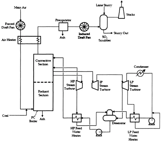
technological challenges, it is important to first understand how a PC power plant works (see Figure 1). In a typical plant, raw coal is milled to the consistency of talcum powder, and fed pneumatically to the boiler in a stream of pre-heated combustion air (Deutch & Moniz, 2006). The coal particles are rapidly heated as they enter the combustion chamber, which pyrolitically decomposes the organic structure within the coal into combustible gases, gaseous tars, and a carbonaceous char particle that includes the ash materials. The gases and carbon combust in the coal flame at temperatures between 2100 and 2700 °F, giving off heat and producing CO2 and water vapor, and leaving behind an
ash residue. Also in the combustion chamber, SO2 and NOn are formed by oxidation of
sulfurous and nitrogenous compounds present in the coal. NOn is also produced through a thermal formation process in which oxygen atoms present in the flame gases react with N2from the combustion air (Williams, et al., 2000).
Fo Draft
Air H
cam
Heate
Figure 1. Pulverised Coal Power Plant without CO2Capture (Adapted from U.S. DOE NETL, 2002)
Heat from the combustion process is transferred to pressurized water through tubes that line the boiler wall, generating high pressure steam for the steam cycle (to be described below). The flue gas leaves the convective section of the combustion chamber at around 600 F, and passes through the air heater after which its temperature is reduced to about 300 °F (U.S. DOE, NETL, 2002). At this point, the flue gas is made up primarily of N2, H20, and CO2.
In modem plants, the flue gas is then treated to meet environmental restrictions before release to the atmosphere. Some plants have a selective catalytic reducer (SCR)
following the air heater, although it is not pictured in Figure 1. The SCR uses ammonia or urea to reduce NOn to N2, although in-boiler controls are often used in lieu of these
13-expensive systems. The flue gas then typically passes through an electrostatic precipitator (ESP) to remove boiler fly-ash, then through an induced draft fan which forces the gases through the system, and maintains a slight negative pressure in the boiler. Finally, a flue gas desulfurizer unit (FGD) is sometimes used to remove SO2when high
sulfur coals are burned (U.S. DOE, NETL, 2002). The treated flue gas is then ejected to
the atmosphere.
The steam cycle is where the energy in the steam is converted to useable electric power. Subcritical PC plants typically have one steam reheat cycle (as shown in Figure 1), although some have a double reheat system. The high pressure steam reaches pressures around 2400 psi and temperatures of 1000 F before being passed through the high pressure turbine. The outlet from this turbine is reheated, then passed through an intermediate pressure turbine, then either reheated again or passed directly to the low pressure turbine. The low pressure turbine outlet is condensed and pumped through a series of heat exchangers, de-aerated, and sent back to the boiler to generate high pressure steam (U.S. DOE, NETL, 2002). All of the turbines are coupled to generators, which produce electricity. PC plants with subcritical steam systems typically have plant thermal efficiencies in the 34-38% range, on a higher heating value (HHV) basis1 (Deutch &
Moniz, 2006).
The steam cycle can be designed to operate at higher temperatures and pressures to improve the efficiency of the plant. Current supercritical steam cycles operate at around 3530 psi and 1050 °F, with an overall plant thermal efficiency of around 38-40%. There
are some "ultra-supercritical" plants in operation at 3850 psi and 1100 °F, and materials
advancements could allow pressures of 5300-5600 psi and temperatures of 1290-1330 °F, reaching efficiencies of 42-45% for bituminous coal (Deutch & Moniz, 2006). For plants with supercritical and ultra-supercritical steam systems, the flue gas processing
1 Thermal efficiency is defined as the percent ratio of electric output to energy fed to the system. For example, a 500 MW plant that is fed 4.88x10⁹ Btu/hr would be 35.0% efficient by the following calculation:
500MW 4.88xOtu/hr*
OOkW
3 4 4Btu *100% =35.0%portion of the plant downstream of the boiler remains essentially the same, as does the flue gas composition. Upgrading an existing subcritical system to supercritical or ultra-supercritical is not a trivial matter, however, and effectively means that the majority of the plant would need to be rebuilt.
It is important to note that improvements in efficiency offered by supercritical and ultra-supercritical systems are equivalent to a reduction in CO2emissions. As efficiency is improved, more electricity is generated from the same amount of coal input and, likewise, the same amount of by-product (including CO2) output. If CO2capture is considered, the fact that there is less CO2produced per kWhe of electricity generated (at higher
efficiencies) means that there is less capture cost per kWhe.
2.1.2 Pulverized Coal Power Plant with CO2Capture
Post combustion CO2capture technology concepts can vary greatly, but the common characteristic is that the capture process takes place following combustion and steam generation. Flue gas properties can be highly variable, depending on the properties of the coal and the configuration of the boiler, but generally fall within the ranges shown in the "Raw" flue gas column in Table 1 prior to flue gas cleaning.
In today's state of the art PC power plants, electro-static precipitators (ESPs), flue gas desulfurizers (FGDs), and often selective catalytic reducers (SCRs) are employed to remove particulate matter, sulfur dioxide (SO2), and nitrogen oxides (NO), respectively. The ESP, FGD, and SCR change the composition of the flue gas in important ways. Table 1 shows typical flue gas properties for a PC power plant that employs these technologies, but does not have a CO2capture system.
15-Flue Gas Analysis
Raw Treated
Temperature (F) 300 129 -143 Pressure (psi) 14.4 14.4 Flow rate (ton/hr)* 2700 - 3200 2800 - 3400
N2 (%) 67 -74 62 -67 H20 Vapor(%) 8 - 15 16 -22 C02 (%) 11 - 12 --11 02 (%) 5 -6 -5 Ar (%) 0.8 - 0.9 0.7 - 0.8 SO2 (ppm) 400 -2300 3 -15 NOx (ppm) 20 -25 2 - 5 HCI (ppm) 30 - 110 3- 10
*On a 500 MWe plant basis.
Table 1. Typical Raw and Treated Flue Gas Properties (IECM, 2005).
The post-combustion capture of CO2is analogous to the capture of other air pollutants; it is the addition of another set of process equipment at some point in the flue gas
processing train. Generally, CO2capture processes are designed to follow the ESP, FGD, and SCR, and these units may require re-optimization or reconfiguration. Acid gases
such as SO2 and NOx can poison solvents in capture processes, and particulate matter can
also degrade solvents and damage process equipment, so a relatively clean flue gas stream may be needed for CO2separation.
The challenge is to remove a significant portion of the CO2from the flue gas stream, at the lowest possible cost. The primary separation is that of CO2and N2. For the purposes of this thesis, it will be assumed that the removed CO2stream will be prepared for
pipeline transportation and geologic storage, which means it must be pressurized higher
than the critical pressure of C02, usually to 100 atm or greater. The CO2 must be nearly
free from non-condensable gases such as N2and 02, so that single phase flow can be achieved, and must be dehydrated to avoid corrosion problems.
The relatively low concentration of CO2in the flue gas makes the separation difficult, and actually eliminates some capture technologies from reasonable consideration. A higher
concentration of CO2 provides a higher driving force for separation processes. This fact
explains why separation from the flue gas stream of a coal-fired plant is more attractive than separation from a gas-fired plant or directly from air, where CO2 concentrations are lower. In addition, it is very significant that the flue gas from a coal boiler leaves the system at atmospheric pressure, and hence has a low CO2partial pressure. Separations which are driven by a high CO2partial pressure differential, such as most membrane separation systems, can essentially be dismissed because of the prohibitive cost of pressurizing such a large volume of gas.
Post-combustion CO2 separation is a major challenge because such a large volume of flue gas is generated. For example, a typical 500 MWe subcritical PC power plant burning
Illinois #6 coal with a HHV efficiency of 35% emits approximately 2.7 million kg/hr of flue gas, of which 463,000 kg/hr is CO2 (Deutch & Moniz, 2006). To put this in
perspective, the same plant produces approximately 12,700 kg/hr of SO2 and 1,900 kg/hr of NOx (most of which is captured in the air pollution control devices). Controlling CO2 is a considerably larger task than previous flue gas pollution control efforts. It requires large process units, large quantities of process energy, and can require large quantities of additional process feedstock.
SO2 and NO, can be serious concerns for CO2 capture systems, even in low
concentrations. Levels of SO2 in the flue gas are a direct function of the sulfur content in the coal, so higher sulfur coal types are more problematic for capture systems than low sulfur coals. NOX levels are a function of nitrogen levels in coal, but more a function of burner design and flame conditions. SO2and NO, can foul solvents in chemical
absorption systems and SO2can cause corrosion. Most chemical absorption systems require that SO2and NOx concentrations be less than 10 ppmv and 20 ppmv, respectively (IEA, 2004). These levels are lower than is currently required, but are attainable with current technology. Existing plants with FGDs would require a modification to achieve these levels, but new plants could be designed to do this at relatively little additional cost. Low NO, burners and an SCR could be used to meet the NO, requirements (FLUOR,
17-2004). For other types of post-combustion capture systems, SO2 and NOx requirements may be different, but the presence of these compounds may still complicate matters.
The oxygen in the flue gas is also a concern for solvent systems, and must be taken into consideration. It rapidly degrades amine solvents, and an inhibitor must be added to the solvent in order for it to survive in the presence of 02 (Roberts, et al., 2005).
2.2 Current Technology/State of the Art
2.2.1 Technology Overview
Post-combustion separation is currently employed in about a dozen facilities worldwide to produce CO2for commercial sale, and the technology used is a chemical absorption system using monoethanaoloamine (MEA) as the absorbent (Herzog & Golomb, 2004). In a PC power plant, the amine system is added to the process following the FGD, just before the flue gases go to the stack, as shown in Figure 2. The balance of the plant essentially remains the same, although some modifications to the steam cycle are
necessary to accommodate the heat requirements in the amine plant. The FGD may also need improvement to further reduce SO2, which otherwise fouls the solvent in the amine
Fot
Drat
A.t'
I-Coal
Heater
Figure 2. Pulverized Coal Power Plant with Amine Scrubbing for CO2Capture (Adapted from U.S.
DOE NETL, 2002)
In a chemical absorption plant, the flue gas is contacted with the MEA in a packed
absorption tower (see Figure 3). The CO2and MEA react to form a protonated amine and a bicarbonate anion in solution by the following reaction:
C2H4OHNH2 + H20 + CO2 -' C2H4OHNH3++ HCO3- (1)
The remaining flue gases are washed to remove any residual MEA, and exhausted to the atmosphere. After filtration and a heat recovery step, the CO2-enriched solvent is passed through a regeneration unit in which counter-current steam drives the reaction to the left, producing a stream of H20 and CO2. The H20 is condensed out, leaving a stream of CO2 that is over 99% pure and prepared for compression. The CO2-lean solvent is cooled and recycled to the absorption tower (Herzog & Golomb, 2004).
19-In addition to the MEA absorbent, Mitsubishi Heavy 19-Industries, Ltd., and Kansai Power Co. have developed a proprietary blend of hindered amines that is used in a similar system (Iijima, et al., 2004). The hindered amine solution is said to have a 67% higher CO2absorption capacity, and a 20% lower heat of regeneration (Iijima, et aL., 2004). This allows for smaller solvent flows and associated pumping costs, and smaller diameter absorbers and strippers. The lower heat of absorption means that less steam is required for regeneration and the energy penalty is lower. The solvent is also resistant to
degradation by oxidation, such that make-up requirements are one-fifth of those of MEA and corrosion problems present by the degradation products are not such an issue (Iijima, et al., 2004). An3 m enmnrQuinl Vent Flue ga from power plant C03 Sludge
Figure 3. Amine Chemical Absorption Process (Adapted from Herzog & Golomb, 2004)
Regardless of solvent choice, the solvent cooling, heating, and pumping processes and the compression of the purified CO2all require energy, and reduce the overall efficiency of the plant. The absorption column and regeneration unit are both expensive capital investments. If this technology is to be implemented on new PC plant builds, these costs must be lowered. Improvements are possible in the heating and cooling processes if
better heat integration techniques are developed. Pumping costs and the capital cost of the units can be reduced if solvent improvements are made which reduce the amount of solvent required. The amount of energy required to compress the CO2from atmospheric pressure (at which the system operates) to a one-phase liquid for pipeline transportation
and storage could also be improved with advanced compressor designs.
2.2.2 C 2Capture Cost
One thing is certain about CO2 capture- it increases both the total plant cost (TPC) and the cost of electricity (COE). Deutch and Moniz performed a study in which TPC and COE were estimated for pulverized coal plants with subcritical, supercritical, and ultra-supercritical steam systems, both with and without capture. Their estimates were formulated based on an analysis of recent design studies, with input from experts in industry, and are summarized in Figure 4. The results show that adding an amine chemical absorption system increases TPC by 54-74% and increases COE by 57-69%, (Deutch & Moniz, 2006). The increase in TPC and COE is more pronounced for less efficient subcritical systems than for the higher efficiency super and ultra-supercritical systems.
Total Plant Cost Cost of Electricity
~2000 I 4 1500 * 00 C 1000 . IL a500 I-I 70 6.0 , . .- a ' *No Captre .! 5.0 *Capture 4 0 UJ 3.0 4. 0 2.0 1.0 00 * No CaptureIl * Capture -. I Subcritica PC Supercritical PC' Ultra- Subcritical PC Supercritical PC'
Ultra-supercritical PC supemrcdtical PC
Figure 4. Total Plant Cost and Cost of Electricity for PC Plants with and without Capture (Adapted from Deutch & Moniz, 2006)
21 -elan : ZWU _.- ... ... _- . . ... I _A _ -. an js v.v _
2.2.3 Plant Efficiency Losses
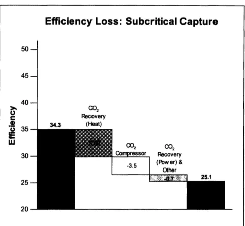
Capturing and compressing CO2is the most expensive part of the capture, transport, and storage process. The costs can be expressed in terms of overall plant efficiency losses, which translate into lost electricity production, and lost revenue. For a subcritical PC system, the losses can be categorized into CO2recovery heat, CO2recovery power, and compression energy. The CO2recovery heat is the steam that is used to heat the CO2 -enriched amine in the regeneration unit. The CO2recovery power is the additional power required to drive the flue gas fan and the sorbent pump which moves the amine solvent through the recovery system. The CO2compression energy is the energy required to compress the CO2to conditions for transport and storage.
Figure 5 shows what typical losses are for a subcritical plant and how these lower the overall efficiency of the plant. For supercritical and ultra-supercritical systems, the same losses would be experienced in terms of category and quantity, although the losses are simply subtracted from a higher original efficiency. For example, an ultra-supercritical plant with an efficiency of 43.3% loses 9.2 efficiency points2to have an efficiency of 34.1% with capture, just as the subcritical plant dropped 9.2 points from 34.3% to 25.1% (Deutch & Moniz, 2006).
2 It is important to make the distinction between "efficiency points" and percentage losses in efficiency. A
loss in efficiency points is a decrease in efficiency where one point loss is equal to one percentage point loss in the overall efficiency. A percentage loss in efficiency is a decrease in overall efficiency as a percentage of the original efficiency. For example, a drop in efficiency from 40% to 30% would be a 10 point efficiency loss, and a 25% loss in efficiency.
Efficiency Loss: Subcritical Capture
5045-
40-.24 U C2 Recovery 34.3 (Heat) (02 (02 Compressor Recovery -3.5 (Power)V
& ' ',7 f' -i
q25.1
20Figure 5. Efficiency Losses by Category for a Subcritical PC Plant with Capture (Adapted from Deutch & Moniz, 2006)
2.2.4 Reliability and Operability Issues
Reliability is highly valued in the electric power industry, both from the perspective of the supplier and the consumer. Consumers demand a power system which provides a steady stream of consistent quality power, with few or no interruptions or fluctuations in voltage. Producers require high availability in order to keep costs low and to recoup investments. The generation, transmission, and distribution of power is a complicated matter, and any factors which limit the reliability or availability of plants are highly undesirable.
Pulverized coal plants without CO2capture currently have very strong and well-tested reliability records. The reliability of amine capture systems has not been tested on such a wide scale, nor has it been performed on the size of gas streams as those found at large power plants (Roberts, et al., 2005). It is not a very complicated chemical process, however, and high availability of the capture portion of the plant is expected.
23 -35
30
One important characteristic of post-combustion capture systems is that they are installed downstream of the steam generation system and are completely separate from the power block, where the electricity is generated. The implication of this feature is that if the
capture system encounters difficulty, the portion of the plant that produces power will be largely unaffected. The plant can continue operation while the CO2is vented to the atmosphere, until the capture system can be brought back online. In essence, a plant with post-combustion capture should be no less reliable than a similarly designed plant
without capture. This is different from such systems as IGCC, which may have to be completely shut down if the capture equipment experiences failure or must undergo maintenance.
2.3 Research Areas/Potential New Technologies
The high cost of capture using amine systems has prompted research into alternative post-combustion CO2capture options and novel improvements to existing technologies. Efforts are focused on bringing down the capital cost or energy penalty of certain parts of the process. For example, much work is currently underway to lower the heat required for regeneration of CO2solvents, because it is such a strong component of the energy penalty of capture, as shown in Figure 5.
2.3.1 Advanced Solvents
A variety of solvents could be used in the absorption/regeneration process, and each has its advantages and disadvantages. The key physical factors in solvent selection are heat of absorption/regeneration, CO2 absorption rate, CO2 absorption capacity, resistance to degradation and impurities, corrosion, and volatility (Cullinane, et al., 2002, Rochelle, 2005). A solvent with a low heat of absorption requires less energy during regeneration, which can lead to significant savings. A solvent with a high absorption rate minimizes absorber size and pressure drop across the absorber and associated pumping costs. A high absorption capacity allows more efficient operation and can reduce solvent volume requirements and equipment size. Solvents with high resistance to degradation reduce solvent make-up costs, and can reduce gas clean-up costs in the stages prior to the absorption system. (Cullinane, et al., 2002). Corrosive solvents are undesirable because
they can shorten process equipment lifetime. Solvent volatility can be an important issue because a volatile solvent can escape with the flue gases and may exceed environmental limits.
These factors must be optimized as solvent research goes forward, and must be balanced when determining which solvent is the most appropriate to use in a plant design.
Regeneration energy, however, is by far the most important factor in affecting cost because of its strong impact on overall plant efficiency, as noted in Section 2.2.3.
MEA has been the most commonly chosen solvent so far, and has often been enhanced with additives to improve its performance. Improvements must still be made, however, for post-combustion solvent absorption/regeneration processes to be a competitive option for CO2capture. It is useful to compare novel or advanced absorbents to MEA because it is in use today. Table 2 shows how a number of alternative solvents compare with MEA, and the following sections give further explanation (Note: hindered amines were
discussed in Section 2.2.1).
-Performance of Alternative Solvents Relative to MEA
Heat of CO2 CO2 Resistance to
Regenerat- Absorption Absorption Degradation/ Corrosion Volatility
__ _ ~ion Rate Capacity Impurities
Stericaily Hindered + ? + + + ? Amines Aqueous
-
+ + + NH3 K2CO3/PZ + + = ? ? Amino-acid + + + +Amekaal
~
?+
+
+
?
+
Salts Alkali- + + + + metals Other AminesPerformance Characteristics Key: + Better, - Worse, = Similar, ? Indeterminate Table 2. A Comparison of Alternative Solvents to MEA
Aqueous Ammonia
There has recently been discussion of using aqueous ammonia as a solvent rather than MEA, in a similar absorption/regeneration process. Ciferno, et al. and Resnick, et al. have published papers that discuss the benefits of using ammonia as a solvent, including a high CO2loading capacity, low equipment corrosion risk, low absorbent degradation, and a low energy requirement for absorbent regeneration (Ciferno, et al., 2005, Resnick, et al., 2004). They also highlight the potential for selling the ammonium sulfate and ammonium nitrate by-products as an additional source of revenue which would help recoup some of the cost of capture.
Both authors claim that there is a significant increase in CO2loading capacity when comparing aqueous NH3to MEA, although they disagree on just how much. Resnick, et al., estimate NH3 solutions to have three times the capacity as MEA, while Ciferno, et al., estimate the increase to be about 25% (Ciferno, et al., 2005, Resnick, et al., 2004). This would allow for smaller solvent flows, and hence smaller equipment and pumping costs.
Ciferno, et al., claim that using NH3could lead to a reduction in steam requirements of up to 67%, and Resnick, et al., claim that steam use could be reduced by 49-64% from an
MEA system (Ciferno, et al., 2005, Resnick, et al., 2004). Because the regeneration steam is one of the principal costs in a chemical absorption system, this is a significant savings opportunity. Additionally, the combination of lower solvent degradation and a cost of NH3 that is about 6-10 times less than MEA leads to significantly lower solvent make-up cost. The bulk of NH3that is degraded would be in the form of ammonium sulfate or ammonium nitrate, both of which are saleable fertilizers3.
There are significant problems with using ammonia as a solvent, however, as identified by Rochelle (Rochelle, 2005). The volatility of ammonia is a major obstacle, because it has a tendency to exit the absorber column to the atmosphere with the flue gas. Rochelle
estimates that the NH3 concentration in flue gas could be as high as 3%, much greater than environmentally acceptable levels of less than 10 ppm (Rochelle, 2005). Steps such as cooling the exit gas or adding a water or acid wash could reduce these levels, but would introduce additional costs and complications that would negate many of the advantages of using ammonia, and there seems to be no apparent practical method to avoid this problem (Rochelle, 2005).
Rochelle also believes that the estimates of Ciferno, et al., and Resnick, et al., of reductions in regeneration steam are optimistic, and the steam requirements would be similar, if not higher, than those for MEA (Rochelle, 2005). Additionally, he argues that the rate of absorption for the NH3process would be much slower than MEA, which may require the absorber to be three times the height of an MEA absorber and add a major increase to the capital cost of the system (Rochelle).
3 The market for ammonium sulphate and ammonium nitrate fertilizers is small compared to the amount of these substances that would be produced if ammonia solvent systems were widespread. It is possible that a major CO2capture effort would result in such an increase in supply of these fertilizers that prices would be
depressed significantly, reducing the benefit of selling the by-products.
-Some key questions that remain are:
1. Can the volatility problem be reasonably solved? 2. Are CO2capacity improvements significant? 3. Are steam regeneration improvements significant?
4. Do the other advantages outweigh the disadvantages of the slow reaction rate?
Piperazine/Potassium Carbonate Solution
Researchers have been investigating the possibility of using an aqueous
piperazine/potassium carbonate (K2CO3/PZ) solution as a replacement for MEA in a chemical absorption system (Cullinane, et al., 2002). The proposed system works in the same manner and has the same configuration as the process shown in Figure 3, except that the solvent is a 5m K+/2.5m PZ solution rather than an MEA solution.
The research has shown that a piperazine/potassium carbonate solution is better than an MEA solution in terms of heat of absorption and rate of absorption, and roughly equal to MEA in CO2capacity (Cullinane, et al., 2002). This solution has a lower heat of
regeneration than the MEA solution translating to a 25 to 49% decrease in regeneration energy (Cullinane, et al., 2002). The piperazine/potassium carbonate solution also has a rate of absorption that is 1 to 5 times faster than MEA, allowing for a smaller absorption column (Cullinane, et al., 2002). The piperazine/potassium carbonate solution has been shown to have a low volatility, reducing the environmental emissions problem that
ammonia faces. The cost of PZ ($2.20/lb) is a little higher than MEA ($0.76/lb) however, which may offset some savings (Cullinane, et al., 2002).
Some key questions that remain are:
1. Is solvent degradation significant?
Amino-acid Salts
Some work has been done to investigate the advantages of using amino-acid salts such as potassium glycinate, potassium taurate, and potassium sarcosine (Feron & ten Asbroek, 2004). Some salts were found to absorb CO2faster than MEA, some could potentially reduce regeneration energy significantly, some have good resistance to degradation, and all have low volatilities (Feron & ten Asbroek, 2004). One distinct advantage that some amino-acid salts have is that they have a particularly high CO2capacity, which could allow for considerably smaller equipment sizes. A complicating factor is that a precipitate forms during absorption, which requires that equipment be able to handle slurries.
These solvents could be especially useful where small equipment size is necessary, such as space-limited sites. Some key questions that remain are:
1. What effects will the precipitate have on process design?
2. Is corrosion a problem?
Alkali Metal-based Sorbents
Alkali metal-based sorbents are another option for capture. These slurries of NaHCO3,
Na2CO3, or K2CO3 can absorb CO2 in a spray dryer or fast transport reactor, and can be
regenerated in a bubbling fluidized bed (Eom, et al., 2005). They have shown high CO2 capacity, high resistance to degradation, and fast reaction times. It is not clear if there is any advantage in the energy requirements of regeneration, although there are claims that regeneration requires less heat than the MEA process (Coker, et al., 2005). More work is required to determine the potential for this technology to be competitive, and some key questions remain:
1. Is there any reason to pursue these sorbents absent a heat of regeneration advantage?
2. Is corrosion an issue?
3. Will volatility or airborne salt dust be an issue?
-Other Amines
The use of other amines, such as diethanolamine (DEA), methyldiethanolamine (MDEA), (butylamino)ethanol (BEA), N-methyldiethanolamine (NMDEA),
2-(methylamino)ethanol (MMEA), 2-(ethylamino)ethanol (EMEA) and 2-(2-aminoethyl-amino)ethanol (AEEA) have been considered as an alternative to pure MEA solutions (Hoff, et al., 2004, Bozzuto, et al., 2001). Blending of these amines and the addition of compounds such as piperazine can also affect performance, and there are certainly other amines that were not listed. MDEA and AEEA have shown improvements over MEA in terms of lowered heat of regeneration and somewhat higher capacity in the case of AEEA, but these are not revolutionary improvements (Hoff, et al., 2004, Bozzuto, et al., 2001). Most other amines have shown poorer performance than MEA, and great
advances should not be expected (Hoff, et al., 2004).
2.3.2 Process Integration
There is the potential to significantly reduce parasitic energy losses if heat integration and novel flow-sheeting methods are used in typical amine absorption systems (Roberts, et al., 2004). Most current designs include stripping steam that is bled from the steam turbine power generation system, which is the most important process integration.
Another improvement that has been suggested is to use the heat generated when
compressing the purified CO2stream in the stripper reboiler (Fisher, et al., 2005). This improvement saves up to 4.6% of CO2removal costs, although it causes a slight increase in capital costs (Fisher, et al., 2005). The stripping column could also be operated at variable pressures, with compressors between each step in the column. In this way, partial CO2compression actually takes place in the regeneration column, and can save 8.4% of capture costs (Fisher, et al., 2005). The two improvements added to the
regeneration system simultaneously could result in a total capture cost reduction of 9.8%, and an overall cost of electricity savings of 5.2% (Fisher, et al., 2005). These are
significant improvements that could be made today, with relatively little additional research and development.
There are probably many other opportunities for cost saving through higher levels of process integration. A major research thrust should be to further reduce the costs of amine absorption systems by taking advantage of potential savings through deeper integration of the capture plant with the rest of the power plant.
2.3.3 Cryogenic Processes
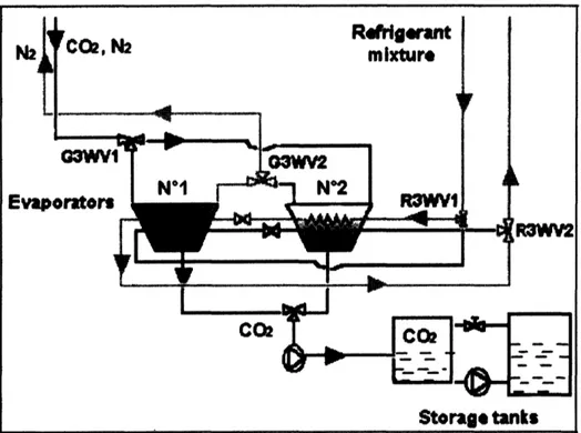
A recent study by a team from Alstom Power and Ecole des Mines de Paris investigated a cryogenic separation technique that takes advantage of the CO2sublimation temperature (frosting temperature) to make the CO2/N2 separation (Clodic, et al., 2005). In this approach, flue gases are cooled by a refrigerant in a heat exchanger to below the frosting temperature of C02, around -120 °C, such that solid CO2builds up on the heat exchanger tubes (see Figure 6). After sufficient solids build-up, the heat exchanger is heated, evaporating a pure stream of CO2 for compression and transportation. Two heat
exchanger/evaporators are used in a swing configuration, with one frosting and the other defrosting. Cold energy in the defrosting exchanger is recovered and used in the frosting exchanger, improving the energy efficiency of the process.
-Figure 6. Alstom/Ecole des Mines de Paris Anti-Sublimation Process (Adapted from Clodic, et al.,
2005)
The authors have built a mock-up model to demonstrate feasibility and estimate
efficiency. At 90% CO2 capture, the anti-sublimation process was estimated to have an
energy penalty of only 3.8 - 7.3 percentage points, which is considerably better than any other processes so far developed (Clodic, et al., 2005). They also cite the possibility that other pollutants could also be captured in such a system, which may eliminate the need for other costly pollution control equipment, such as FGDs.
Key questions surrounding this concept are:
1. How does this concept compare to the MEA process on an economic basis? 2. Do the anti-sublimation/sublimation and heat transfer processes happen fast
enough such that equipment size is reasonable?
It should be noted that other cryogenic processes, such as low temperature distillations and an adaptation of the Ryan-Holmes process used by the natural gas industry have been discussed, but are generally found to be impractical.
2.3.4 Other Technologies
Stimulus-Responsive Separation Aids and Structured Fluids
There is some interest in separation processes that are based on stimulus-responsive separation aids and structured fluids. Stimulus responsive separation aids rely on small changes in process operations to effect large changes in capacity (Herzog, 2002). An example of such a system is the carbon fiber composite molecular sieve that is being developed at Oak Ridge National Laboratory. This is a monolithic electrically
conductive carbon adsorbent composed of carbon fibers bound by a phenolic resin, and it operates by adsorbing CO2when gases are flowed through it, then desorbing it when a current is passed through the sieve (Judkins & Burchell, 2001).
A structured fluid is a separation aid that self-assembles reversibly to first capture then release CO2(Herzog, 2002). An example of a structured fluid (which, incidentally, is also a stimulus responsive separation aid) is a liquid crystal system which could capture CO2then release it when an electric current is passed through (Herzog, 2002). These processes are only in the beginning stages of research, but have the potential to dramatically reduce the energy required to make a CO2 separation.
Lithium Zirconate Temperature Swing Adsorption Wheel
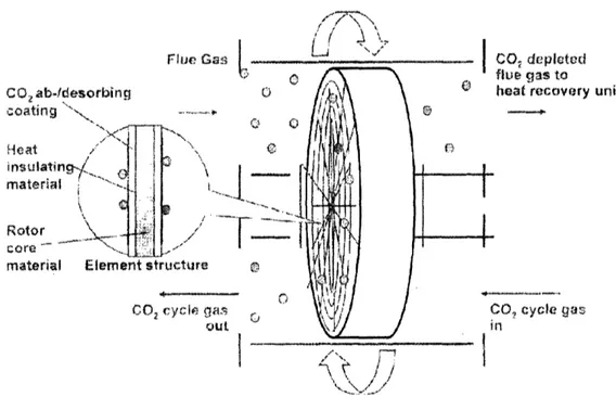
A mechanism has been proposed for removing CO2by adsorption on a solid lithium zirconate surface in a novel concept that allows for a continuous process (see Figure 7). In this technique, CO2is adsorbed to Li2ZrO3which coats a rotating wheel by passing flue gas across the rotor at temperatures in the range of 450-600 °C (Alstom, 2006). After the adsorbed CO2 is moved 180° around the track of the rotor, it is removed by a
hot sweep gas. The CO2is then cooled and compressed, and the CO2-depleted flue gas is cooled and vented to the atmosphere (Alstom, 2006). This process is similar to chemical absorption because it is limited by the heat of regeneration of the adsorbent.
-33-LJ
~
/
Flue GasI
C02 ab-desorbing coating ' -...Heat
/
insulatingI
Rotor corematerial Element structure
CO
2cy(t
If-
I
CO, depleted"I,/ , .
---
'\N Ii i
Figure 7. Lithium Zirconium Wheel Diagram (Adapted from Alstom, 2006)
Molten Carbonate Membranes
Some consideration has been given to other novel separation techniques. One such approach is to use molten carbonate to transport carbon in the form of carbonate ions across a membrane (Granite & O'Brien, 2005). The advantage to using molten carbonate is that it is nearly 100% selective for C02, it has a relatively high conductivity, and could
potentially have a low parasitic power requirement (Granite & O'Brien, 2005). However, it is very corrosive, is poisoned by SO2, can degrade if temperatures are too high, and requires huge stacks to scale up to match the requirements of a power plant (Granite & O'Brien, 2005).
Solid electrolyte membranes
Solid electrolyte membranes could do the same job as molten carbonate and avoid some of the corrosion and degradation problems, but there are still major difficulties with the membrane technology (Granite & O'Brien, 2005). Much work is required to make molten carbonate or solid electrolyte membranes a reality.
flue gas to heat recovery unit
DO? cycle gas
n
Membrane contactors
Membrane contactors are another technology which can improve CO2 capture processes,
and can be used in place of absorber and stripper columns in the amine chemical absorption process (Herzog, 2002). The advantage to membrane contactors is that they can increase the surface area for the absorption and stripping process, allowing for much smaller equipment sizes (Herzog, 2002). This savings is partially offset by the cost of the membrane, however. This type of capture system is best suited for situations in which space is limited.
2.4 Chapter Conclusions
Post-combustion capture of flue gas CO2is a viable option for CO2 control. The current state-of-the-art systems use MEA chemical absorption/regeneration systems to achieve capture, although with high additional capital costs and a high energy penalty. MEA capture increases TPC by 54-74% and COE by 57-69%, depending on which type of steam system is employed. The bulk of the energy is lost in regenerating the solvent and compressing the CO2for transport and storage.
There are a number of technological solutions under development now in attempts to reduce the cost of capture for post-combustion systems. Several alternative solvents have been investigated, each having their advantages and disadvantages, but none seems to be clearly superior to MEA. Deeper integrations of a chemical absorption system into the overall plant could yield some significant gains without requiring revolutionary
innovations. Some novel concepts, such as the cryogenic CO2 frosting process, stimulus-responsive separation aids and structured fluids, the lithium zirconate wheel, and some membrane processes have also been investigated and may have some advantages, including reducing heat of regeneration requirements.
What is clear is that there is a lot of uncertainty about which processes could lead to real improvements, and which really have no real prospects for reducing the cost of capture. When reviewing the literature, it is difficult to compare processes or technologies that have been studied by different groups because they each have different bases for analysis,
-35-and they often inject optimism into their analyses. Technologies should be carefully -35-and objectively analyzed, and efforts should be made to reduce uncertainty and bias.
3.0 Oxy-fired Technology
Oxy-fired coal combustion technology has been discussed as a solution for bringing down the cost of capturing CO2. Some small-scale demonstrations of oxy-firing have been done, and some pilot scale plants are planned, but oxy-fired coal power plants have not otherwise been deployed at a large scale. Using oxy-fired technology can offer improvements over capturing CO2from post-combustion flue gases, but absent capture, there is currently no incentive to use oxy-firing for the coal power production.
3.1 Overview
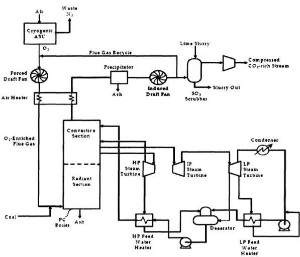
In a typical oxy-fired PC design, the plant is very similar to a conventional PC power plant, as described in Section 2.1.1. The feed system, boiler, steam system, and ESP are
essentially the same, but a portion of the flue gas is recycled following the ESP, and a cryogenic air separation unit (ASU) is used to provide 95% pure oxygen to the boiler (see
Figure 8).
In this system, the primary separation is N2and 02 prior to combustion, so that the flue gas is made up primarily of CO2and water vapor (U.S. DOE, NETL, 2002). The purification of CO2and preparation for transport and storage is thus made much easier and less expensive than for an air-fired system. The flue gas recycle step is necessary to control flame temperature and stability and to ensure proper heat flux in the boiler (Buhre, et al., 2005). Most oxy-fired designs are designed with a supercritical steam cycles, at around 3530 psi and 1050 °F, with an overall plant thermal efficiency of around 30% (Deutch & Moniz, 2006).
-37-IV Alst Foei D raft Air He Co2-E Coill Heater
Figure 8. Oxy-fired Pulverized Coal Power Plant with CO2Capture (Adapted from U.S. DOE
NETL, 2002)
There are several features that differentiate oxy-fired systems from conventional PC power plants. The 02 content of the gas feed to the boiler is higher, typically around 30%, compared to the 21% 02 gas (air) which is fed to a conventional boiler (Buhre, et
al., 2005). The high CO2/H20 gas in the furnace has a higher gas emissivity, which
allows the same radiative heat transfer with a smaller volume of boiler gases than a PC system (Buhre, et al., 2005). The flue gas volume prior to CO2purification and
compression is decreased by about 80%, although it is a higher density gas and has higher concentrations of contaminants on a per volume or per mass basis (Buhre, et al., 2005).
The technology needed for an oxy-fired system is available today; it does not require any major breakthroughs to build and operate one. Pilot-scale operations have been built, but
none at any larger scale have been developed because incentives to capture the CO2 are
not in place, and there is no reason to use this technology except for CO2capture (Deutch & Moniz, 2006). The Babcock and Wilcox Company has reported flame stability, 65% NOx reductions, and CO2concentrations of 85% in the flue gas (with 5% air infiltration) in a pilot-scale study (The Babcock and Wilcox Company, 2006). Boiler operation showed no negative impact, unburned combustibles were lower or the same, and furnace exit gas temperatures, convective pass heat absorption, and boiler exit gas temperature were similar to an air-fired case in this study (The Babcock and Wilcox Company, 2006).
A demonstration plant is planned for Hamilton, Ohio, where a 24 MWe coal-fired power plant will be retrofitted with oxygen feed and flue gas recycle (The Babcock and Wilcox Company, 2006). It will undergo performance testing and should offer some insight into how the retrofit and operation of an oxy-fired system at a larger scale will work.
Vattenfall, a Swedish company that owns power plants in Germany, has plans to build a 30 MWth lignite burning oxy-fired boiler in Germany by 2008 (Ing & H/ge, 2005). This boiler will built from the ground up and will be designed for oxy-fired combustion. It will test the entire process, from coal feed to CO2compression and liquefaction, with
complete interconnection of the combustion and gas processing chain (except it will not have full steam cycle). The plant will demonstrate interaction of components and the basic procedural principles, and will prepare Vatenfall to complete their plans to build a 300-600 MWth demonstration plant by 2015 and a 1000 MWth or greater full commercial plant by 2020 (Ing & Hige, 2005).
3.2 Current Technology/State of the Art
3.2.1 Technology Overview
There are three distinctive features of an oxy-fired system: 1) the cryogenic air separation unit, 2) the flue gas recycle system, and 3) and the CO2purification and compression system. These systems must be well understood in order to identify potential problems and areas for improvement.
-39-Cryogenic Air Separation Unit
Cryogenic oxygen production is a mature technology, and only minor improvements can be expected in reducing the cost or energy demands of the cryogenic ASU process (Simmonds, et al., 2005). It is currently the only large-scale technology for oxygen production from air, and will probably be the air-separation technology utilized in the first generation of oxy-fired power plants (Jordal, et al., 2005). Most oxy-fired systems assume 95% pure oxygen from the ASU (the remainder being primarily argon), although this could be adjusted up to purities greater than 99%, or down (Jordal, et al., 2005). Higher purity oxygen is more expensive both in terms of capital and operating cost, however, and it generally offers little additional benefit to use oxygen more pure than 95%. The cryogenic ASU consumes roughly 20% of the plant gross power output when used in an oxy-fired system (Jordal, et al., 2005). Supplanting cryogenic ASU with a less expensive and less energy-intensive air separation technology would be a major
development in reducing the cost of CO2capture, and some leading options will be discussed later.
Flue Gas Recycle
As mentioned previously, flue gas recycle is necessary to control flame temperature and stability, to control heat flux properties in the boiler, and to maintain boiler temperatures below the ash melting point. There are two different types of flue gas recycle, external recycle and internal recycle. In external recycle, the flue gas stream is split after
particulate removal, and ductwork is used to deliver a portion of the flue gas back to the boiler. The current state-of-the-art for oxy-fired combustion systems is to use external
flue gas recycle. Typically, 60-70% of the flue gas is recycled (Deutch & Moniz, 2006, Buhre, et al., 2005). In internal recycle processes, which are used in the glass and steel industry, high momentum oxygen jets induce a recycle flow within the boiler (Buhre, et al., 2005). Internal recycle will be discussed in Section 3.3.3.
CO2Purification and Compression
Requirements for purified CO2stream conditions may vary depending on the target use for the CO2(storage, EOR, other) and on legal, regulatory, and environmental issues
(Jordal et al., 2005). For example, if it is acceptable to co-sequester CO2, SO2, and NOx
from both a technical and regulatory standpoint, then some expensive processing steps, such as FGD, can be eliminated. Generally, it is accepted that the CO2stream must be greater than 95% pure, essentially free from non-condensable gases such as N2, Argon, and 02, free from water (to reduce corrosion and avoid formation of hydrates), free from particulate matter, and pressurized to about 110 atm (Jordal et al., 2005, Mancuso, et al., 2005).
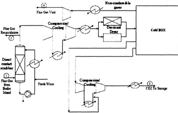
Figure 9 shows a possible design for a CO2purification and compression plant that could be integrated into an oxy-fired power plant (Mancuso, et al., 2005). In this scheme, flue gas at 80 °C (stream 1) is first directly contacted with cool water in a scrubber tank, where the majority of the moisture in the flue gases are condensed out and any remaining particulate matter is also removed (Mancuso, et al., 2005). A portion of the flue gas is then recycled, and the remainder goes through a compression and cooling process before being further dried in a desiccant drying system. In the cold box, there is a two stage flash tank system which separates the non-condensable gases, which are then passed through an expander turbine to recover some useful energy, and then vented. The
purified flue gas is compressed to 110 atm and cooled to ambient conditions for pipeline
transport and storage.
-S$o
Figure 9. CO2Purification and Compression Plant (Adapted from Mancuso, et al., 2005)
This is just one design for a purification and compression system. Other designs are possible, and steps can be taken in other parts of the power plant that would make purification simpler. For example, firing the boiler with as little excess 02 as possible
and designing and building a boiler that allows very little leakage air in reduces the presence of non-condensable gas, reducing purification requirements (Jordal et al., 2005).
3.2.2 C02 Capture Cost
As with post-combustion systems, adding CO2capture increases both the TPC and the COE over a no-capture plant. Recent estimates of TPC and COE for a supercritical plant both with and without oxy-firing and CO2 capture are summarized in Figure 10 (Deutch
& Moniz, 2006). These results show that using oxy-firing with CO2capture increases TPC by 43% and increases COE by 46% over a no-capture plant, and these numbers are consistent with other estimates and from small-scale industrial experiences (Deutch & Moniz, 2006). These TPC and COE projections are lower for an oxy-fired system than for PC plants with today's commercial amine capture systems.
Ye A__ 1
Total Plant Cost Cost of Electricity osnn .. | n n~~~~~~~~~~~~~~~~~~~~~~~~~~~~~~~~~~~~~~~~~~~~~~~~~~~~~~~~~~~~~~~~~~~~~~~~~~~~~~~~~~~~~~~~~~~~~~~~~~~~~~~~~~~~~~~~~~~~~~~~~~~~~~~~~~~~ £wAJ1 . - 8.0 (U 6.0 a No Capture .' 50 Capture 40 40 *~~~ mu ao 2.0 0.0 :.. * No Capture . Capture
Supercritical PC Supercritical Oyfired Supercritical PC* Supercritical Oxfired
*Amine Syat emfor CaptureCase 'AmineSyd m forCaptureCamw
Figure 10. Total Plant Cost and Cost of Electricity for Supercritical PC Plants without Capture and with Oxy-Firing (Adapted from Deutch & Moniz, 2006)
3.2.3 Plant Efficiency Losses
As in the amine capture systems, there is significant energy consumption for an oxy-fired plant with capture, which results in overall losses in plant efficiency (Deutch & Moniz, 2006). For an oxy-fired PC system, the primary losses can be categorized into ASU energy, compression energy, and other losses. There is actually a slight gain in efficiency due to improvements in boiler efficiency and reduced energy usage in the FGD, but this is more than offset by the losses. A large amount of energy is required in the ASU to make the primary separation of N2from 02. The CO2compression energy is the energy required to compress the CO2to conditions for transport and storage, and the other losses can be mainly attributed to the energy requirements of the CO2purification system and the flue gas fan. Figure 11 shows what typical losses are for a supercritical oxy-fired plant and how these lower the overall efficiency of the plant relative to a supercritical plant without oxy-firing and capture.
-43 -,.0 1500 In a 0 00 U o 500 I-0 M