Autonomous Navigation and Tracking of Dynamic
Surface Targets On-board a Computationally
Impoverished Aerial Vehicle
by
William Clayton Selby
B.S., United States Naval Academy (2009)
Submitted to the Department of Mechanical Engineering
in partial fulfillment of the requirements for the degree of
Masters of Science in Mechanical Engineering
at the
MASSACHUSETTS INSTITUTE OF TECHNOLOGY
0 F TELOGY
|
1
JUL
2
9
2o11
LIBRARIES
ARCHNES
June 2011
©
Massachusetts Institute of Technology 2011. All rights reserved.
A uthor ...
.. c A . .... .. ./.... . . .
Department of M fanical Engineering
May 6, 2011
Certified byD...
Daniela L. Rus
Professor of Electrical Engineering and Computer Science
ThessSypervisorC
C ertified by
...
John J. Leonard
Professor of Mechanical Engineering.
/
<IWaurlTEngineering Faculty Reader
A ccepted by ..
...-.
David E. Hardt
Chairman, Department Committee on Graduate Students
Mechanical Engineering Department
Autonomous Navigation and Tracking of Dynamic Surface
Targets On-board a Computationally Impoverished Aerial
Vehicle
by
William Clayton Selby
Submitted to the Department of Mechanical Engineering on May 6, 2011, in partial fulfillment of the
requirements for the degree of
Masters of Science in Mechanical Engineering
Abstract
This thesis describes the development of an independent, on-board visual servoing system which allows a computationally impoverished aerial vehicle to autonomously identify and track a dynamic surface target. Image segmentation and target tracking algorithms are developed for the specific task of monitoring whales at sea. The computer vision algorithms' estimates prove to be accurate enough for quadrotor stabilization while being computationally fast enough to be processed on-board the platform. This differs from current techniques which require off-board processing of images for vehicle localization and control. The vision algorithm is evaluated on video footage to validate its performance and robustness.
The quadrotor is then modeled to motivate and guide the development of Linear Quadratic Regulator (LQR) controllers for maneuvering the quadrotor. The con-trollers are tuned using a motion capture system which provides ground truth state measurements. The vision system is integrated into the control scheme to allow the quadrotor to track an iCreate. Additionally, an Extended Kalman Filter (EKF) fuses the vision system position estimates with attitude and acceleration measurements from an on-board Inertial Measurement Unit (IMU) to allow the quadrotor to track a moving target without external localization.
Thesis Supervisor: Daniela L. Rus
Title: Professor of Electrical Engineering and Computer Science Mechanical Engineering Faculty Reader: John J. Leonard
Acknowledgments
This thesis would not have been possible without the support of a large group of friends, family, and colleagues. I would primarily like to thank my advisor, Daniela Rus, whose seemingly unlimited energy kept me motivated and excited throughout this research. Her wide ranging interests in all aspects of robotics allowed me unique opportunities to apply this research to a multitude of related projects. I would also like to thank my computer vision mentor, Peter Corke. Peter's wide range and experience in visual servoing helped guide key design choices in vision as well as control. I am especially grateful for the time spent at his lab at QUT in Australia.
I am especially grateful to my fellow Distributed Robotics Lab colleagues who took
time from their own research to take critical looks at mine. Daniel Soltero was in-valuable as a second hand when running experiments. Kyle Gilpin and Marek Doniec provided very valuable hardware advice that saved countless hours of debugging. I would also like to thank Abe Bacharach of the Robust Robotics Group at MIT for access to several key software components for this research and his extensive quadro-tor control knowledge. I am especially grateful to Brian Julian for his experience in dealing with the quadrotor platform as well as his large knowledge of control and estimation theory. I wish all my lab mates the most of luck in their future endeavors. Finally, this work could not be done without the support of my family. The support of my mother Julie, father Doug and sister Taylor was invaluable and I appreciate it greatly.
Contents
1 Introduction 1.1 Contributions . . . . 1.2 Thesis Overview. . . . . 2 Related Work 2.1 General Background ...2.2 Quadrotor Development and Applications
2.3 Object Recognition . . . . 2.4 Visual Control of Aerial Vehicles . . . . .
2.5 Context for This Research . . . .
3 Experimental Set-up
3.1 Laboratory System Architecture . . . .
3.1.1 Experimental Hardware . . . .
3.1.2 Software Architecture . . . .
3.2 Camera Model and Calibration . . . .
3.2.1 Camera and Lens Selection...
3.2.2 Pinhole Camera Model . . . .
3.2.3 Lens Distortions . . . .
3.2.4 Camera Calibration . . . .
3.2.5 Calibration Results . . . .
3.2.6 Camera Settings Configuration . .
3.3 Quadrotor Dynamic Model . . . .
27 . . . . 2 7 . . . . 2 8 . . . . 3 0 . . . . 3 1 . . . . 3 3 35 . . . . 3 6 . . . . 3 7 . . . . 3 9 . . . . 4 0 . . . . 4 1 . . . . 4 2 . . . . 4 3 . . . . 4 5 . . . . 4 7 . . . . 4 9 . . . . 5 2
3.3.1 Model Adaption ... 56
3.3.2 Parameter Estimation and Model Verification . . . . 58
3.4 Extended Kalman Filter . . . . 61
3.4.1 Process M odel . . . . 62
3.4.2 Measurement Model . . . . 64
4 Object Identification and Tracking 69 4.1 Color M odels . . . . 70
4.2 Pixel Classification . . . . 71
4.3 Image Segmentation and Object Description . . . . 72
4.4 Tracking Multiple Objects . . . . 75
4.5 Position Vector Calculation . . . . 76
5 Controller Design 79 5.1 LQR Derivation . . . . 79
5.2 LQR Implementation . . . . 82
6 Experimental Results 89 6.1 Experimental Set-up, Methodology, and Metrics for Object Identification 90 6.2 Results of Object Identification Algorithms . . . . 92
6.2.1 Tracking with an Overhead Perspective . . . . 92
6.2.2 Tracking at an Angled Perspective . . . . 93
6.2.3 Tracking from the Surface . . . . 95
6.2.4 Performance Comparison of View Angle . . . . 96
6.2.5 Boat Identification . . . . 97
6.3 Experimental Set-up, Methodology, and Metrics for Visual Servoing . 98 6.4 Results of Visual Servoing Experiments . . . . 100
6.4.1 Visual Servoing With Motion Capture Output . . . . 101
6.4.2' Visual Servoing with EKF Output . . . . 101
6.5 Experimental Set-up, Methodology, and Metrics for Dynamic Object Tracking . . . . 102
6.6 Results of Dynamic Object Tracking Experiments . . . 103
6.6.1 Dynamic Object Tracking with Motion Capture Output . . . 103
6.6.2 Dynamic Object Tracking with EKF Output . . . . 104
7 Conclusions 107
7.1 Lessons Learned... ... 108
List of Figures
1-1 Quadrotor Tracking a Dynamic Surface Target . . . . 16
1-2 Various Forms of Currently Used Unmanned Aerial Vehicles . . . . . 17
1-3 The Ascending Technologies Hummingbird Quadrotor in Flight . . . . 18
1-4 Sample Frame From Video Footage Recorded in Argentina . . . . 20
1-5 Tracking of Projected Whale Video Footage . . . . 22
3-1 Quadrotor Outfitted With fit-PC2 and Firefly MV2 . . . . 35
3-2 Views of the iCreate Target Used for Hardware Experiments . . . . . 36
3-3 Experimental Network Topology . . . . 37
3-4 Experimental Software Architecture . . . . 39
3-5 Pinhole Camera Model . . . . 42
3-6 Effects of Radial Distortion . . . . 44
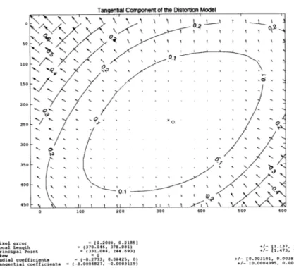
3-7 Effects of Tangential Distortion . . . . 45
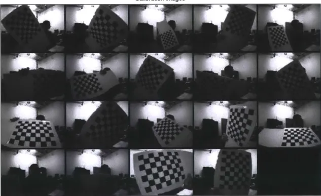
3-8 Chekerboard Images Used for Calibration . . . . 47
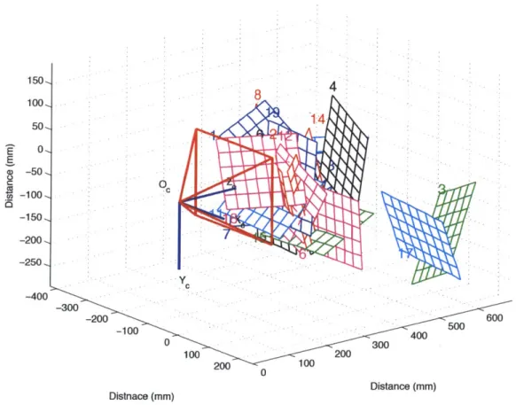
3-9 Camera Centered View of Estimated Checkerboard Locations . . . . 48
3-10 Raw Image Before and After Distortion Correction . . . . 49
3-11 Effects of Default White Balance Values . . . . 50
3-12 Effects of Corrected White Balance Values . . . . 51
3-13 Quadrotor Structural Diagram . . . . 52
3-14 Rotational Dynamics Block Diagram . . . . 57
3-15 Translational Dynamics Block Diagram . . . . 58
3-16 Comparison of Simulated Rotational Dynamics and Ground Truth . . 59
3-18 3-19 3-20 4-1 4-2 4-3 4-4 5-1 5-2 5-3
Integration Errors Due to IMU Drift . . . . Comparison of Acceleration Estimates and Ground Truth Values Comparison of Altitude Estimates and Ground Truth Values . . Image Thresholding in the Hue and Saturation Planes.
Target Recognition Through Contour Identification . Simultaneous Tracking of Multiple Targets . . . . Weighted vs. Unweighted Position Vector . . . . Simulink LQR Controller Block Diagram . . . .
Simulink Feedback Block Diagram . . . . Simulated LQR Trajectory Tracking . . . .
6-1 Sample Frame From Footage Recorded at an Overhead Perspective .
6-2 Sample Frame From Footage Recorded at an Angled Perspective . . .
6-3 Sample Frame From Footage Recorded at a Surface Perspective . . .
6-4 Sample Frame From Boat Footage . . . .
6-5 Comparison of EKF Output to Ground Truth . . . .
6-6 Visual Servoing Utilizing Motion Capture State Feedback . . . . 6-7 Hovering Utilizing EKF State Estimation . . . . 6-8 Quadrotor Target Tracking Ground Truth Positions Utilizing Motion
Capture State Feedback . . . .
6-9 Quadrotor Target Tracking Ground Truth Positions Utilizing EKF State Feedback . . . .
6-10 Vision System Performance With EKF State Feedback . . . . 7-1 Future Work Integrating Vision System With AMOUR AUV
. . . . . . . . 71 . . . . 73 . . . . 76 . . . . 77 . . . . 86 . . . . 87 . . . . 88 93 94 95 98 100 101 102 103 105 105 . . . . 110
List of Tables
3.1 Comparison of Camera Calibration Methods . . . . 49
6.1 Properties of Video Clips Analyzed . . . . 91
6.2 Vision System Results: Overhead Perspective . . . . 93
6.3 Vision System Results: Angled Perspective . . . . 94
6.4 Vision System Results: Surface Perspective . . . . 96
6.5 Properties of Video Clips Analyzed . . . . 97
6.6 Vision System Results: Boat Identification . . . . 98
6.7 Dynamic Object Tracking: Motion Capture State Feedback . . . . 104
Chapter 1
Introduction
We wish to develop an autonomous control system for a Micro Aerial Vehicle (MAV) which uses visual position estimates to identify and track surface targets without rely-ing on external processrely-ing. MAVs are characterized by their small size and payload. Due to the payload constraints, on-board sensing and processing is limited. Such platforms could be used as "remote eyes" to collect data quietly and accurately from a distance. Applications include recording ecosystems without interfering with the behavior of animals, collecting data for situational awareness, or performing targeted surveillance.
Current UAVs and Their Applications
Research and development in the field of Unmanned Aerial Vehicles (UAVs) has been progressing at an astonishing pace. The availability to own and operate such sys-tems has increased while the price has been dropping dramatically. The wide-spread availability of Global Positioning Satellite (GPS) systems has enabled the develop-ment of advanced control systems, allowing novice pilots to simply provide high-level waypoint commands to the vehicles. Low materials and sensor costs in addition to the development of open source software has given amateur developers access to sophis-ticated tools which have dramatically increased the breadth and depth of research in the field as well as opened the platforms for a wide array of applications. While the most well known applications of UAVs are for military operations such as Intelligence, Surveillance and Reconnaissance (ISR), UAVs have been used to measure atmospheric
Figure 1-1: Quadrotor Tracking a Dynamic Surface Target
conditions and pollution, facilitate disaster relief and emergency management, serve as a communications relay, and assist in search and rescue operations.
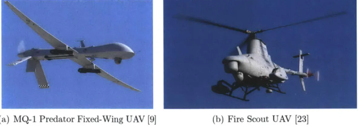
Currently, fixed-wing UAVs are used for the majority of these missions since the UAVs typically fly in open airspace void of any real obstacles. These vehicles are usu-ally large, can carry substantial payloads allowing them to perform all computation on-board, and rely on GPS for position estimation. The MQ-1 Predator UAV shown in Figure 1-2(a) is a well-known fixed-wing platform used in military operations. How-ever, their size and reliance on GPS make fixed-wing UAVs unsuitable for applica-tions in an urban environment. The dynamics of fixed-wing platforms require forward movement for continuous flight making navigation in an urban environment difficult. Additionally, their reliance on GPS for position information becomes a hazard in ur-ban areas where large buildings may cause severe GPS dropouts. Autonomous indoor navigation would be extremely difficult due to the size and maneuverability of current fixed-wing UAVs as well as the lack of GPS reception.
Rotary-wing UAVs seem uniquely suited to operate in this cluttered urban envi-ronment. Rotary-wing UAVs have several advantages over their fixed-wing counter-parts. Primarily, a rotary-wing vehicle is not required to maintain a forward velocity
(a) MQ-1 Predator Fixed-Wing UAV [9] (b) Fire Scout UAV [23]
Figure 1-2: Various Forms of Currently Used Unmanned Aerial Vehicles to sustain flight. The ability to hover permits the vehicle to make heading changes in cluttered environments which would not be possible with the turning radius of a fixed-wing vehicle. Additionally, the ability to hover allows the platform to maintain a sensor's field of view on a single target for extended periods of time. The ability to vertically takeoff and land (VTOL) reduces the launch and recover footprint of the vehicle, thus making it easier to deploy and retrieve. VTOL capability also elimi-nates the need for landing strips or other launch assisting devices such as catapults. The MQ-8A Fire Scout shown in Figure 1-2(b) is a typical UAV of the traditional helicopter design.
Traditional helicopters are mechanically complex systems. A large main rotor is used to provide lift as well as translational motion. A swash plate assembly on the main rotor hub allows the pilot to adjust the angle of the main rotor blades during flight. In order to prevent the body of the vehicle from spinning due to the counter torque of the main rotor, an additional tail rotor is need. To drive the the tail rotor, a long drive shaft runs from the main rotor's transmission to a smaller transmission in the tail rotor through the tail boom. Furthermore, the tail rotor extends beyond the footprint of the main rotor which increases the area required to maneuver the helicopter safely.
The fundamental quadrotor design has remained relatively simple and eliminates some of the mechanical complexities characteristic of the traditional helicopter design. Four rotors are mounted in a symmetrical pattern equidistant from the vehicle's
center. The motors directly drive the rotors which eliminates the need for a gear box. Since combustion engines typically have a slow response, electric motors are used to adjust the rotor speed at the high frequency needed for stable control. While multiple motors increase the payload capacity of the platform, they also increase the vehicle's weight and energy consumption. With four inputs but six degrees of freedom, the quadrotor is a classic under-actuated system. It is impossible to move in a translational direction without changing the attitude of the vehicle. These fast and under-actuated dynamics make it an ideal platform for controls research. The Ascending Technologies Hummingbird quadrotor is a research level platform which can be seen in Figure 1-3.
Figure 1-3: The Ascending Technologies Hummingbird Quadrotor in Flight
Motivation
This thesis describes the development of a small, quiet, and computationally lean robotic flying camera system that can be used to automate data collection in sup-port of environmental studies. Our key application domain is surveillance at sea-observing objects such as whales and boats where the target stands out against a relatively uniform background. This problem has two aspects we address using com-puter vision:
1. Using the vehicle's vision system to detect and track objects at sea.
2. Autonomously controlling the robot using visual position estimates.
Observing whales is important for many marine biology tasks including taking census, determining family lineage, and general behavioral observations. Currently, whales are observed manually using binoculars and cameras from the shore or boats. Notes of their behavior are typically made using pencil and paper. The process is error prone, non-quantitative and very labor intensive. Human-operated planes and helicopters are also used, but the data gathered this way is limited. Planes fly at high altitude, can not hover, and the data collected is limited in duration and precision. Traditional helicopters can hover and fly closer to the sea surface, but they are noisy and drive the whales away.
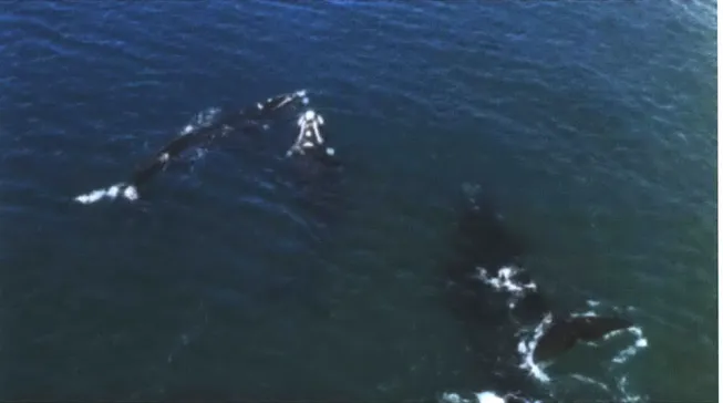
In our first field experiments we used a small hovering UAV to automate the data collection of whales. Figure 1-4 shows a typical frame from this video data set. We found that the robot is quiet enough to fly close above the water surface and not disturb the whales. The robot can hover and adjust its velocity to track the whales and capture their natural behavior with images of unprecedented detail. These field experiments were done between August 20-25 2009 when a joint MIT and Argentinean Whale Conservation team deployed a remote control Ascending Technologies Falcon 8 robot over the sea at Peninsula Valdez, Argentina to collect data on Southern Right whales. The team completed several successful missions of approximately fifteen minutes each, during which the robot was manually piloted over groups of whales and video was recorded. Using this data, the goal in this thesis is to create a computationally impoverished flying robot system that relies on vision-based position estimates and only on-board processing to navigate, detect whales, and track whales in order to automate these types of field experiments. This is different than existing systems that use additional sensors such as GPS or laser scanners for position estimates or perform off-board processing of the video stream.
Figure 1-4: Sample Frame From Video Footage Recorded in Argentina
Method of Approach
The whale tracking algorithm performs object recognition using a pixel-level clas-sifier and domain knowledge. Image hue and saturation values are suitable invariants to segment whales from other elements in the scene. A two-dimensional mathematical model is created to describe the target. In subsequent frames, individual pixels are evaluated and assigned a probability of being a target pixel based on their hue and saturation values as compared to the target model. Groups of high probability pixels are identified as objects and presented to the user.
The algorithm was evaluated and extensive results obtained over 13,000 frames representing Southern Right whales, Blue whales, Grey whales, and Humpback whales. The data was collected from a variety of angles under varying lighting conditions. The results of these tests showed 98.99% recall for 3,537 frames of Southern Right whale footage collected in Argentina. To show adaptability to varying target types, over
5,823 frames of video footage containing boats was evaluated as well. This footage
also displayed the ability of the vision system to track multiple targets with varying characteristics simultaneously.
The visual servoing control system is built upon the object identification and tracking algorithms. This ability to position the quadrotor above a moving target is demonstrated through several indoor experiments. The vision system serves as a high level path planner, creating a desired trajectory to position the quadrotor over the target. A traditional quadrotor model is adapted to include the dynamics of an on-bard attitude controller and the model parameters are learned through a system identification process. This model is used to formulate Linear Quadratic Regulator (LQR) position controllers in order to maneuver the quadrotor to a desired state. The additional payload of the on-board computer and camera makes control difficult. The weight is essentially a non-aligned constant disturbance which has to be accounted for with constant offsets and integrator control. Velocity state control is also necessary for precise position control. This requires accurate velocity signals from either motion capture data or an Extended Kalman Filter (EKF). The camera is operated at sixty frames per second, but due to the on-board computational limitations, the vision system is run only at ten to twenty frames per second. The control commands are computed at forty hertz.
Our methodology for designing these algorithms begins with developing a base-level controller using a motion capture system that provides highly accurate vehicle state feedback at a high frequency. The vision system is used to track a designated target. The target for the hardware experiments is the iCreate robot as shown in Figure 1-1. For proof of concept of outdoor tracking, the whale footage was projected onto the floor and the quadrotor identified the simulated whales in the image. A sample image from this experiment is shown in Figure 1-5. Additionally, we remove the external localization system and replace it with visual position estimates for controlling the robot. The vision system position estimates are fused with on-board Inertial Measurement Unit (IMU) data in an EKF to estimate the state of the vehicle. The robot was able to reliably track the moving surface target independent of any external localization source. This ability would be useful for urban environments or indoor settings when external localization such as GPS temporarily drops out or is completely unavailable.
Figure 1-5: Tracking of Projected Whale Video Footage
Technical Challenges
A key challenge in this thesis is to avoid the reliance on an external processing
source in order to develop a system robust to communication dropouts. A communi-cation link is often used to transfer images and control commands between the robot and a ground station. Wireless bandwidth may be limited in areas and not provide the means to transmit images at a servoable frequency when processed off-board. While image compression techniques could increase transmission rate, it could also create artifacts which may negatively impact the performance of computer vision al-gorithms. Any delays in the system could result in unstable flight trajectories due to the fast and under-actuated dynamics of the quadrotor. The system resulting from this research is therefore capable of operating at longer ranges and is generally safer than one relying on external processing.
Computational efficiency is a key issue in this work and considerable time was taken to develop a vision algorithm that was not only accurate but also computa-tionally fast. Initially, image gradient-based feature tracking was used to track the intended target, however this was abandoned for the proposed method using hue
and saturation values. The proposed method is highly user intuitive and produces accurate results for varying video footage quality.
The fast dynamics of the quadrotor require a fast controller for stabilization. A classical PID controller was implemented initially but was replaced by a set of LQR controllers derived from a validated system model. The quadrotor's fast dynamics also amplify any delays in the system and creates instability. The system architecture was modified to utilize a global system timestamp to more accurately process sensor measurements which improved the state output of the filter. Hardware pieces were designed and redesigned to reduce weight as much as possible. In the end, these challenges were overcome to produce an autonomous visual servoing system utilizing only on-board computation.
1.1
Contributions
The ability for MAVs to autonomously navigate in an outdoor environment in-dependent of external processing and localization is currently a highly desirable yet elusive capability. Current independent outdoor navigation systems rely on a com-bination of GPS and Inertial Navigation System (INS) measurements processed on-board a microcontroller. Alternatively, systems using cameras or laser scanners for localization and control rely on off-board processing. There is a need for systems that are able to navigate in unknown and/or GPS denied environments. In turn, autonomous reliable navigation will enable solutions to higher-level tasks such as exploration and multi-vehicle trajectory planning. While large UAV systems have utilized on-board computation for image processing and localization, this capability is currently unavailable for smaller MAV systems. An autonomous MAV is essential for indoor operation or environments where agile movement is critical.
Towards these goals, our contributions include:
e Fast Object Representation and Identification Algorithms for Computationally
Impoverished Platforms - An image segmentation algorithm is presented which
proved to be of high accuracy while being computationally efficient enough to run in real time. This algorithm was tested on varying object types, can be used
to track multiple objects of differing characteristics, and is capable of creating a trajectory to servo a vehicle.
" Model Adaptation, Simulation, and Controller Synthesis - The classical
quadro-tor model is adapted to take advantage of the on-board attitude stabilization system. The model is developed in MATLAB's Simulink toolbox with parame-ters learned from real test flight data. This infrastructure can be easily adapted for other quadrotor types and be used to simulate and validate various types of position controllers. Based on the validated model, LQR position controllers are designed and implemented.
" On-board IMU and Monocular Vision Based Control for a Computationally
Im-poverished Platform - A control scheme is developed for completely on-board
visual servoing. Both the control and image processing algorithms are executed on-board the quadrotor platform. The visual position estimates are used to create a desired trajectory along with motion capture state feedback. Further, the visual position estimates and on-board IMU data are used as inputs to an EKF to provide accurate state estimation with minimal delay.
" Experimental Verification of the Visual Servo Control Schemes - In physical
hardware experiments, the performance of the vision and control systems were evaluated. The iCreate target was programmed to move in a varied trajectory at a constant speed. Utilizing the motion capture system for state feedback, the quadrotor tracked a surface target using position estimates from the vision sys-tem. Estimated state feedback computed on-board was then used to maneuver the quadrotor as it reliably tracked the iCreate.
1.2
Thesis Overview
This thesis is divided into six chapters. Chapter 2 presents related work in the areas of quadrotor vehicles, image segmentation and identification, and visual servo-ing. Chapter 3 describes the experimental set-up to motivate the development of the object identification algorithms as well as the visual servoing control systems. The
camera modeling and calibration process is discussed as well as the quadrotor mod-eling and system identification process. This chapter also explains the development of the EKF used for state estimation. Chapter 4 discusses the development of the image segmentation algorithm as well as the target tracking algorithm. Chapter 5 describes the derivation of the low level controller for stable quadrotor flight. Chap-ter 6 presents an evaluation of the proposed vision algorithms utilizing whale video footage. The results of several experiments utilizing the vision algorithms to track a moving surface target are also presented. Chapter 7 concludes the thesis and presents lessons learned as well as several areas of future research.
Chapter 2
Related Work
This thesis builds upon a large body of work in:
e Developing MAV systems.
e Developing algorithms for object recognition and tracking. e Developing visual servoing control systems.
2.1
General Background
The quadrotor is not the most well known form of a rotary-wing vehicle, yet its unique design dates back to August 24, 1907 when the Breguet-Richet Gyroplane No.
1 lifted a few feet off the ground in France [58]. This model used a single engine to
drive all the rotors and was therefore underpowered and lacked a proper means of control. It was not until 1956 that D. H. Kaplan demonstrated the ability to control the aircraft attitude using differential thrust [33], but this design modification has stayed consistent through current production and research models.
Popular hobby models today include the MiKroKopter [68] and the Dragan-flyer [46]. Recent advances in on-board microprocessors, micro-electro-mechanical-systems (MEMS) inertial sensors, high density power storage, and integrated minia-ture actuators have enabled these quadrotor vehicles to be outfitted with on-board attitude stability. This drastically increases the ease of use of the platform and has made the quadrotor more accessible to amateur pilots and researchers. The Parrot
AR Drone has two on-board cameras and is able to be flown via an iPhone ap-plication [26]. The microdrone md4-200 is also a commercially available quadrotor platform equipped with an on-board camera [63].
On-board cameras are becoming one of the most common sensors on-board both commercial and research quadrotor platforms. Typically the cameras are used for surveillance and inspection operations. Computer vision techniques are currently being applied to identify and track marine animals to aid marine biologists [53,54,79] and even to help mitigate damage to whales during US Navy sonar operations [83]. Currently, research is being done in the area of visual odometry which allows the quadrotor to stabilize based on feedback from the vision system [2]. When Global Positioning Satellite (GPS) reception is available, outdoor systems can utilize target tracking algorithms to follow a target by creating a series of desired GPS waypoints
[52].
2.2
Quadrotor Development and Applications
Current research in the control of quadrotors has its origins in research by Hauser et al. who used a minimum phase approximation with input-output linearization on a Harrier jump jet aircraft model [36]. This method was later improved beyond slightly nonminimum phase systems to strongly nonminimum phase systems by Martin et al.
[61]. Shim et al. evaluated the effectiveness of linear multi-variable control, fuzzy logic
control, and nonlinear tracking control on a traditional helicopter model [84]. Using a similar traditional helicopter model, Frazolli et al. presented a tracking controller which avoided the artificial singularities introduced from attitude parameterization
[31]. Young et al. developed a quadrotor tail-sitter vehicle which combined a
flying-wing design with quadrotor propulsion. This unique design resulted in a vehicle with both hover capability as well as high-speed aerodynamic efficiency [92].
Extensive modeling of the quadrotor platform in the early 2000's as well as the development of advanced control techniques for attitude stabilization marked the beginning of considerable research interest in this platform. Hamel et al. developed a generic quadrotor model which included aerodynamic and gyroscopic effects in
addition to the airframe and motor dynamics [35]. A joint collaboration between Commonwealth Scientific and Industrial Research Organization (CSIRO) and the Australian National University lead to the development of the "X-4 Flyer" quadrotor platform [75]. The second generation was presented in 2004 [78] which improved the mechanical design based on simulation results and extensive modeling of roll and pitch rotor damping as well as blade flapping [22]. The authors were able to achieve stable attitude control in the roll and pitch axis in tethered flight [22] and even outdoor autonomous flight [77]. Early work using vision feedback as a primary sensor was done by Altug et al. [5]. A ground camera was used to estimate the pose of the helicopter and a feedback linearizing controller as well as a backstepping-like controller were presented.
With over a decade of research into the modeling and control of the quadro-tor platform, the vehicle has become popular in aerial vehicle research around the world. cole Polytechnique Fdrale de Lausanne (EPFL) has developed the "OS4" quadrotor [11,12], the French Alternative Energies and Atomic Energy Commission's
(CEA) unique quadrotor used four blades per motor [70], and Cornell's Autonomous
Flying Vehicle was built using commercially available parts [72]. Stanford developed a quadrotor known as STARMAC which is used to implement decentralized control algorithms [40]. Utilizing the STARMAC platform, controllers have been designed which compensate for blade flapping and thrust variation while performing a com-plicated stall turn maneuver [41,45]. MIT's Aerospace Controls Laboratory (ACL) developed the Real-time indoor Autonomous Vehicle test Environment (RAVEN) system to evaluate algorithms for multi-agent missions as well as low-level controller performance [42].
Research has now progressed beyond design, construction, and basic attitude sta-bilization of the quadrotor platform and into investigations of control strategies for advanced trajectory following. The Ascending Technologies quadrotors have enabled researchers to focus on position control by providing platforms with robust on-board attitude controllers [34]. MIT's ACL developed simple LQR controllers based on lin-earized quadrotor dynamics which allow multiple aerial vehicles to follow unique
tra-jectories simultaneously [89]. Salazar-Cruz et al. utilized nonlinear control laws with nested saturations to stabilize the quadrotor around simple planar trajectories [81]. Lupashin et al. used a learning strategy to perform high-speed simultaneous flips with the quadrotor [60]. At the University of Pennsylvania, Mellinger et al. developed ag-gressive trajectories which allowed quadrotors to maneuver through small windows and perch on nearly vertical surfaces [66].
2.3
Object Recognition
The field of computer vision has an extremely large literature in image segmen-tation, object represensegmen-tation, and object tracking. Several novel image processing methods have been introduced and improved. This thesis uses image thresholding techniques based on the Hue-Saturation-Value (HSV) color space. It was shown that object identification has distinct advantages when using the HSV color space com-pared to the classical RGB color space in [87].
Traditional segmenting methods rely on image thresholding by assigning pixels to a user defined number of classes. Otsu's method is an "optimal" thresholding algorithm which minimizes the variances between pixels in a class while maximizing the variance between classes [74]. Similarly, the Niblack algorithm [71] uses infor-mation about neighborhoods of pixels but requires extra tuning parameters which would make the resulting system vulnerable to lighting or environmental changes in the image. Techniques such as graph cuts and Maximally Stable External Region (MSER) work well on real world scenes but are computationally expensive. In graph cuts, each pixel is a vertex and edges are computed as the absolute value of the dif-ference in color between pixels on the edge. After each iteration, edge weights below a certain threshold are removed and the adjoining pixels are classified as a single vertex [15,29,80]. MSER considers the set of all possible thresholding values of an in-tensity image and groups pixels into regions whose size remains relatively unchanged across varying threshold levels [62].
The methods described are unique in that they attempt to automatically segment the image into different regions. An alternative approach is to describe the intended
target by isolating certain characteristics of the target such as color or texture. This results in creating histograms which describe the entire image in terms of a specific characteristic. Hopefully, the intended target can be identified by a distinct peak in the histogram. Algorithms such as k-means clustering attempt to optimally isolate the strongest peaks in the data [18,49,51]. The Meanshift algorithm [32] differs from k-means by removing assumptions about the number and shape of the clusters. This algorithm performs gradient ascent on the histogram to find relative maxima in the data. All bins associated with the same peak are clustered together and can be used to identify and track a target [21]. The Camshift algorithm is an extension of the Meanshift algorithm which adapts the peak searching window size and has been used to segment moving targets [4]. Integral histograms developed by Porikli claim to be more accurate and computationally efficient than the Meanshift algorithm [76].
Additional methods are based on a known model of the intended target. If the cameras are fixed and the background is constant, foreground extraction techniques can be used as well as motion detection to identify targets moving in the image
[16, 18, 91]. If labeled information is available, classifiers can be trained on sample
data to learn a model of the object in a technique known as template matching [47, 57]. Also, particle filter based tracking algorithms have been applied to the tracking problem resulting in the Condensation algorithm [56,90].
Instead of analyzing the relationship between the camera's position and a target in the image frame, visual odometry attempts to extrapolate the camera's position and orientation using features in the image. Popular feature detectors today include
SURF [8] and SIFT [59] which use the RANSAC algorithm [30] for outlier detection. By detecting the movement of these features through several frames, the motion of the
camera can be estimated [73]. Monocular SLAM techniques have also been developed to localize the camera system based purely on visual information [24].
2.4
Visual Control of Aerial Vehicles
A good review of vision based control of aerial vehicles is found in [55]. The goal of
system. Typically aerial navigation systems involve the use of a GPS sensor [6,50,52] to provide accurate target tracking capabilities.
Cameras are quickly becoming an important sensor for autonomous navigation because they are small, passive, and consume low amounts of power. Other quadro-tor systems use additional sensors such as laser scanners to provide accurate pose estimation but these can be heavy and a power burden [2,38]. Laser scanners often utilize SLAM techniques to estimate position which is not only highly computation-ally expensive, but also may require prior knowledge of the environment. Soundararaj et al. and Ahrens et al. performed visual SLAM to navigate a quadrotor in an indoor environment relying on off-board computation [3,86]. Stereo cameras are also popular but this technique loses accuracy as the distance from the target increases [43].
There has been a specific interest in using visual position estimates for autonomous landings, but these systems often use special landing pads that allow accurate position and attitude estimation [48,67,82]. The reliance on a predefined target is not practical when the system needs to track targets of varying and unknown characteristics.
Many vision-only systems require off-board computation since the platform is too small to carry a computer capable of executing the necessary algorithms at a fast
enough frequency [19, 20,27, 88]. Additionally, many of these vision-only systems have no means of estimating altitude [19,69]. Instead, an additional sensor is used or the altitude is controlled manually.
Finally, the vision system developed in this thesis is based on the estimated cen-troid of the intended target. Many vision systems use feature finding techniques such as optical flow [19,39,65,86]. Soatto et al. [85] developed forms of the implicit Ex-tended Kalman Filter (EKF) which incorporated vision based measurements into the EKF by making use of the epipolar constraint. Roy et al. utilized a machine learning classifier to distinguish targets from the background and perform geo-location of the identified target [37]. The estimated target position was then combined with a GPS position to autonomously track a moving vehicle.
At the time of this thesis, current work at Eidgenssische Technische Hochschule Zrich (ETH) is progressing towards the development of systems using visual feedback
fused with IMU data processed on-board a quadrotor platform. Pollefeys et al. [64] developed the PIXHAWK platform which utilizes four cameras for localization, pat-tern recognition, and obstacle avoidance. Computation occurs on-board two separate dual core processors and an artificial marker localization scheme is used. Siegwart et al. [10] use visual SLAM techniques to control the position of a tethered quadrotor vehicle. In untethered experiments, a specific circular landmark was used to extract the vehicle state from image information [28].
2.5
Context for This Research
This research builds upon the previous literature in several distinct areas. The basic nonlinear model of the quadrotor was taken from the literature and modified by altering the control inputs as well as estimating the dynamics of the on-board attitude controller. Many models use desired motor speeds as control inputs. However, the quadrotor used in this thesis had an on-board attitude controller to compute the motor speeds. Since we did not need to perform any aggressive maneuvers with the vehicle, aerodynamic effects such as blade flapping were ignored.
In the discipline of computer vision, this research diverges from the computation-ally expensive image segmentation methods such as graph cuts or k-means clustering. Otsu's method, for example, only works for two distinct pixel classes and would be unsuitable for this application where the target and background could have similar characteristics. Instead, we use the HSV color space as suggested by previous work to create a simple yet accurate two-dimensional model of the target. This method is computationally fast, easily portable, and open to user interaction.
The control schemes we present in this research build upon previous work combin-ing computer vision-based feedback and control. Feature based localization is useful for navigating static indoor environments but can provide noisy and inaccurate ve-locity estimates when applied to a static and slightly uniform background such as the ocean. Some vision-based localization methods rely on off-board camera systems which are not practical for our proposed scenario. Reliance on off-board computation requires images and control commands to be transmitted wirelessly, leaving room for
interference with the signals. By performing the computation on-board, this system avoids these complications as well as potential time delays. The method of altitude estimation in this research is accurate at low altitudes which is advantageous when compared to pressure sensors which have significant drift errors. The combination of feedback from a vision system and IMU measurements has been successfully imple-mented in the previous work of others. We take this feedback strategy and implement the state estimation and image segmentation completely on-board the vehicle. The result is a visual servoing system which utilizes vision-based position estimates and
IMU measurements for control without relying on external localization or
process-ing. This makes our system capable of operating without GPS updates for extended periods of time.
Chapter 3
Experimental Set-up
We address the problem of tracking objects at sea by using an autonomous quadrotor robot equipped with a downward-pointing camera and an on-board computer. In this section we detail the hardware and software architecture of this system and highlight the intrinsic constraints that have motivated our solution to visual object recognition and visual servoing. We also describe the specifics of the experiments used to validate the proposed control strategy in hardware. The quadrotor was tasked with identifying and tracking a programmable surface target.
3.1
Laboratory System Architecture
We utilize an Ascending Technologies Hummingbird [34] quadrotor extended with a CompuLab fit-PC2 computer and a Point Grey Firefly MV2 camera. The quadrotor is controlled using the vision-based control strategy we describe in Chapter 5 with position estimates from the object identification and tracking algorithms we present in Chapter 4. A Vicon motion capture system is used to measure the ground truth pose of the quadrotor and the target.
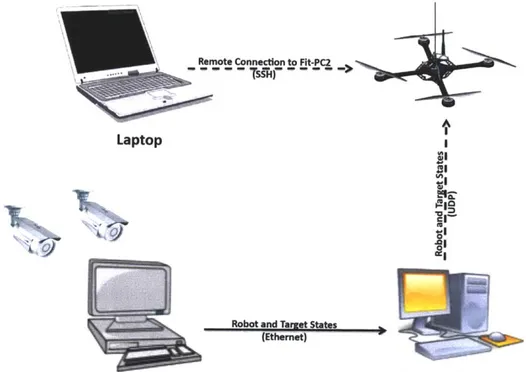
The network topology for the hardware experiments is summarized graphically in Figure 3-3. The solid lines represent wired Ethernet connections and the dashed lines represent wireless connections. This figure includes the computers necessary to use the Vicon motion capture system. This system outputs the position and attitude of the quadrotor and target at 120 Hz with sub-millimeter accuracy and minimal delay. The motion capture data is forwarded to the fit-PC2 via an 802.11 UDP connection.
A laptop is used to remotely run the commands on the fit-PC2 via a wireless SSH
connection but no computation is performed on the laptop during the experiments.
(a) Target Used for Experiments (b) Vision System Output of Target
Figure 3-2: Views of the iCreate Target Used for Hardware Experiments The target for the robot tracking experiments was a 21.5 x 28.0 cm blue clipboard mounted onto an iRobot iCreate as shown in Figure 3-2(a). The iCreate was pro-grammed to follow a specific trajectory at a constant speed and direction. For these experiments, the iCreate moved at a desired speed of 2.5 cm/s. Figure 3-2(b) shows
a sample output frame of the vision system tracking the iCreate.
A
Laptop I
vi
Robot and Target States (Ethernet)
Vicon Motion Capture System Base Station
Figure 3-3: Experimental Network Topology
3.1.1
Experimental Hardware
The vision system is used to provide high-level position control of an Ascending Technologies Hummingbird quadrotor vehicle. The Hummingbird is 40 x 40 x 10 mm in size weighing 550 g out of the box. The maximum recommended payload is 200 g for a flight time of twelve minutes running off a single 11.1 V Lithium Polymer (LiPo) battery. On-board, the Hummingbird is equipped with a Global Positioning Satellite
(GPS) receiver, compass, and a Micro Electro-Mechanical Systems (MEMS) gyro.
Autonomous position control is executed by sending low-level attitude commands to the on-board attitude stabilization control via a serial interface. It is possible to modify the on-board pre-programmed attitude control system, but this is typically only done when the quadrotor needs to execute harsh maneuvers. For this research, the quadrotor was intended to hover stably and the on-board attitude controller was sufficient.
The standard Hummingbird quadrotor is outfitted with at fit-PC2 computer and Firefly MV2 camera system. A bracket was 3-D printed to mount the camera and
fit-PC2 to the bottom of the quadrotor. A USB to serial cable was used to interface with
the quadrotor AutoPilot board and a power cable split the on-board battery power between the quadrotor and fit-PC2. A significant experimental issue was powering the equipment. The full system combines for a total payload of 535 g, well above the recommended maximum payload of 200 g for this platform. The additional weight combined with the added power requirements of the computer and camera results in a flight time of about six minutes, roughly half the normal flight time. The final experimental configuration of the quadrotor is shown in Figure 3-1.
All computation is executed on-board a CompuLab fit-PC2. This computer is
only 101 x 115 x 27 mm in size and weighs 300 g. It operates off the same 11.1 V battery as the quadrotor and consumed 8 W at full CPU load. The fit-PC2 contains an Intel Atom Z550 2 GHz processor with 2 Gb of RAM. It is equipped with 6 USB 2.0 ports, an 802.11n WLAN card, and is booted from a 16 Gb SD card. The solid state drive is more robust to crashes than the common disk drive and is also very lightweight.
Currently, popular on-board computation systems such as the Gumstix rely on the ARM processor. However, the Atom processor has several unique advantages when compared to other processors. Primarily, since it uses the x86 architecture, it enables the user to install standard operating systems. This processor also allows for the use of standard drivers for devices such as the wireless network card and Firefly camera. This results in a system that can be easily reproduced and upgraded. Additionally, the Intel Performance Primitives (IPP) are available for the Atom processor. This performance library can be integrated with the open source computer vision libraries (OpenCV) [17] to boost performance of common image processing and computer vision functions.
Images are transferred over a USB 2.0 connection from the Firefly MV2 to the fit-PC2. The images are downsampled to 320 x 240 pixels. For the visual servoing experiments, the intended target is relatively large in the image. Therefore,
down-sampling does not result in a loss of a large amount of information about the target. This improves computational efficiency without a large sacrifice in accuracy. The camera is capable of 640 x 480 pixels at sixty frames per second but in practice the on-board computation limitations results in a frame rate around twenty frames per second. Off-board processing of the image would require wireless transmission of image data. This additional processing and potential for interference would further reduce the frame rate.
3.1.2
Software Architecture
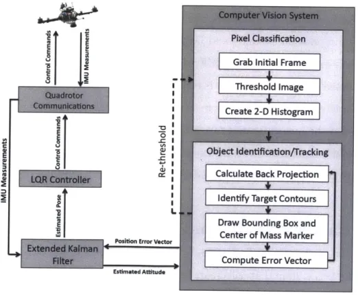
The software architecture is described in Figure 3-4. Several modules are run simultaneously on the fit-PC2. Message routing between modules as well as data logging is handled by the Lightweight Communications and Marshaling (LCM) library [44]. Developed by the MIT DARPA Urban Challenge Team, LCM was designed for tightly-coupled systems connected via a local-area network. These libraries are targeted at real-time systems where high-bandwidth and low latency are desired.
Pixel Classification
Grab Initial Frame
Threshold Image Create 2-D Histogram
E Object identification/Tracking
Calculate Back Projection Identify Target Contours
Draw Bounding Box and
Center of Mass Marker
Positon Error Vector
Compute Error Vector
Estimated Attitude
The vision system module uses the algorithms described in Chapter 4 to identify the target in the image frame. Additionally, Equations 3.19, 3.20, and 3.21 are used to compensate for the vehicle's attitude, convert the vision system position estimates from image plane coordinates in pixels to a body coordinate frame in millimeters, and estimate the vehicles altitude. This module runs at ten Hz due to the additional processing of the vision algorithms.
The control module utilizes four independent LQR controllers described in Chap-ter 5 to compute the roll, pitch, yaw and thrust commands. It receives the full state pose of the robot either from the motion capture module or from the EKF module depending on the experiment being run. The on-board AutoPilot software computes the individual motor commands. The position control commands were calculated at forty Hz.
The quadrotor communication module is used to interface with the quadrotor AutoPilot board. This module receives Inertial Measurement Unit (IMU) measure-ments and transmits control commands via a USB to serial connection. This module operates at thirty Hz.
The EKF module, which is discussed in more detail in Section 3.4, receives the vision system position estimate and IMU measurements. The estimated pose of the quadrotor is extracted from the EKF which is used to calculate control commands. The estimated pose from the filter is computed at 110 Hz.
Not depicted in the figure is the motion capture module which receives the ground truth pose of the quadrotor and target from the motion capture system. Depending on the specific experiment, this information is used to control the robot as well as log the ground truth positions of the quadrotor and target. This system operates at 120 Hz.
3.2
Camera Model and Calibration
The first step to computing accurate computer vision algorithms is to model the camera and lens system that will create the images necessary for the vision algorithms. Cameras of different qualities produce different images of the same scene. While
more expensive cameras are designed to minimize these errors, the small, portable, and inexpensive cameras desired for this research are not constructed to such high specifications. The primary errors in camera images are caused by radial and tan-gential distortion. In order to calibrate the camera, it is necessary to compute both the intrinsic and extrinsic properties of the camera. Fortunately, there are methods to classify the camera and lens parameters to rectify the images of these errors which we discuss in Section 3.2.4.
The vision algorithms we developed rely on accurate color space image segmenta-tion. The more varied the color characteristics of the target when compared to the background, the better the algorithms perform. To improve the color capture and rep-resentation it is necessary to properly calibrate the camera. Once the target has been successfully identified we need to accurately know the target's location. The output of the vision system is the estimated target centroid position in meters. For this esti-mate to be accurate, all camera distortions need to be taken into account. The control strategy for positioning the quadrotor relies heavily on an accurate transformation of the target centroid from pixel coordinates to robot coordinates. Removing the effects of these distortions has a direct impact on the accuracy of the visual servoing control system.
3.2.1
Camera and Lens Selection
We chose the Point Grey Firefly MV2 which has a 1/3" progressive scan Comple-mentary MetalOxideSemiconductor (CMOS )(Aptina MT9V022) image sensor. The camera weighs only 30 g and has a maximum resolution of 752 x 480 pixels at sixty frames per second. This camera is commonly used in robotics due to its lightweight
and compact form, strong API, and high resolution at fast frame rates. Images are pulled from the camera via a USB 2.0 High-Speed interface. While the camera is similar in size to a webcam, it produces images of machine vision grade quality. Since the camera uses a global shutter, it avoids the edge artifacts caused by the rolling shutter in typical CMOS cameras.
A Tamron 1/3" lens is chosen as well. With a 2.2 mm focal length, the field of
and therefore the target. The lens weighs 41.3 g and a ring lock prevents accidental adjustment after the lens has been focused. The lens also contains JR elements which improve the brightness of the images regardless of lighting conditions. The wide angle lens causes significant image distortion which is accounted for in the camera calibration process.
3.2.2
Pinhole Camera Model
The simplest model of the camera is known as the pinhole camera model which is depicted in Figure 3-5. The focal length relates the size of the image on the image
P ( XYZ)
I".
Center of 0Principal Axis
Projection
Image Plane
Figure 3-5: Pinhole Camera Model
plane to the size of the image in real life. In the idealized pinhole model, the focal length,
f,
is the fixed distance from the center of projection to the image plane. The pinhole model is characterized by Equation 3.1.X
V = + C4
42
Equation 3.1 maps a point PG in the physical world with coordinates (X, Y, Z) to the point P on the image plane with coordinates (u, v) and is known as a projective transform. The values F and F. represent the physical focal length in distance units such as millimeters. The principal point (c,, cy) is the estimated center of the image plane. Since the image sensor cannot be perfectly placed, the principal point represents a translation from the optic axis to the center of the image coordinate frame.
In order to compute the values of the point (u, v) in pixels, it is necessary to calculate the focal lengths in pixel units. This is done with Equation 3.2.
(3.2)
fy= F * sV
Here
f,
and fy are the focal lengths of the lens in pixel units. This value is computedby taking the product of the physical focal length in millimeters (F, Fy) and the size
of the imager elements (s,, sy). This model assumes rectangular pixels which causes
sx and s, to be distinct values with units of pixels per millimeter. While neither the focal lengths (Fx and Fy) or the scaling factors (sx and sy) can be measured directly without taking apart the camera, their products (fx and fy) can be estimated through a camera calibration process.
3.2.3
Lens Distortions
Due to difficulties in manufacturing a perfect lens as well as exactly aligning the optical axis of the lens with the imager center, image distortions occur. The two main types of distortion are known as radial distortion and tangential distortion.
Radial distortion is evident when the lens distorts the pixels near the edge of the image. This type of distortion is commonly known as the "fish-eye" effect. Radial distortion occurs when the light rays enter the lens on the outer edges and are refracted more strongly than if they had entered at the center of the lens. While expensive lens systems and high-end cameras can take measures to reduce this distortion, radial distortion is pronounced on lower end camera systems such as the one used for this
research.
0 100 200 300 400 500 600
Pixl er1 [0.2000, 02185)
Focal Len.gtho (378.046 38081) +- 1 [0137, 0 .131]
Princpal Point int0 (331.84. 244.693) +-. t 1.473, 1 1.397]j0 Radial coeffoiients (-0.2733, 0.08425, 0) - (0.003101, 0.0038101, 0] T.nootial coefficienots (-0.0004827, -0.0003119) +/1- [0.0004395, 0.00037261
Figure 3-6: Effects of Radial Distortion
Radial distortion is estimated with a polynomial function which is a Taylor series expansion around r = 0. Here r = Vu2 + v2 which implies that r = 0 is the center of the image plane. The value of r is symmetrical which removes the even coefficients in the expansion. Additionally, since f(r) = 0 at r = 0, the first term in the expansion is also removed. The remaining structure is f(r) = kir2 + k2r' + k3r+ + --.. However
only the first two terms are generally needed in the calibration process. Equation 3.3 summarizes the equations used to estimate the radial distortion in an image.
UC= -u(1 + kir2
+
k2r)
oc = v(1 + kir2 + k2r4)
In this equation, (u, v) is the original location of the distorted point, (uc, vc) is the corrected location, and ki are the estimated radial distortion coefficients. Figure 3-6 shows the effects of radial distortion on the Point Grey Firefly MV2.
Tangential distortion is caused by the misalignment of the imager surface and the lens. In cheaper cameras, these are not always exactly positioned. Tangential