Publisher’s version / Version de l'éditeur:
Questions? Contact the NRC Publications Archive team at https://publications-cnrc.canada.ca/fra/droits
L’accès à ce site Web et l’utilisation de son contenu sont assujettis aux conditions présentées dans le site
LISEZ CES CONDITIONS ATTENTIVEMENT AVANT D’UTILISER CE SITE WEB.
Internal Report (National Research Council of Canada. Institute for Research in Construction), 1997-12-01
READ THESE TERMS AND CONDITIONS CAREFULLY BEFORE USING THIS WEBSITE. https://nrc-publications.canada.ca/eng/copyright
NRC Publications Archive Record / Notice des Archives des publications du CNRC :
https://nrc-publications.canada.ca/eng/view/object/?id=985d383c-4482-4a98-85a0-eea9b6dd1ac8 https://publications-cnrc.canada.ca/fra/voir/objet/?id=985d383c-4482-4a98-85a0-eea9b6dd1ac8
Archives des publications du CNRC
For the publisher’s version, please access the DOI link below./ Pour consulter la version de l’éditeur, utilisez le lien DOI ci-dessous.
https://doi.org/10.4224/20331633
Access and use of this website and the material on it are subject to the Terms and Conditions set forth at
Flanking Transmission at Joints in Multi-Family Dwellings. Phase 1: Effects of Fire Stops at Floor/Wall Intersections
Intersections
Nightingale, T.R.T. and Halliwell, R.E.
www.nrc.ca/irc/ircpubs IRC-IR-754
By T.R.T. Nightingale and R.E. Halliwell
Internal Report IRC-IR-754
December 1997
This report was supported by a Consortium including:
Canada Mortgage and Housing Corporation Forintek Canada
Gypsum Manufacturers of Canada National Research Council Canada
New Home Warranty programs of Ontario, Alberta, British Columbia, and Yukon Ontario Ministry of Housing
Owens Corning Fiberglas Canada Inc. Roxul Inc.
EXECUTIVE SUMMARY
Fire stops can introduce a physical connection between the two sides of a double-stud wall, hence providing structural flanking paths for transmission of vibration which worsens the sound insulation.
This study primarily addressed the specific case of a load-bearing party wall with double wood studs, supporting a floor with wood joists perpendicular to the party wall and a floor deck or sub-floor of 15.9 mm OSB.
Even without structural transmission of vibration through a fire stop, the sound insulation in a real building is normally affected by flanking transmission.
Addition of a fire stop provides yet another path for vibration transmission between the rooms, and hence tends to worsen the sound insulation further. This study examines how a fire stop at the floor/wall junction can degrade the apparent sound insulation of the party wall (the nominal separation) by increasing structural transmission of vibration around that wall via the connected floor system (the flanking path).
Group 0 Constructions have no physical fire stop. Adding batt insulation to fill the wall’s inter-stud cavities leaving a gap of 25 mm or less (Case 2) improves sound insulation provided by the party wall itself while adding negligible structural transmission. Strictly speaking, this is not a fire stop, but it does provide the necessary fire resistance (as shown in the companion study of fire spread) and meets the prescriptive requirements for fire separations in the National Building Code.
Group 1 Constructions do not transmit significant vibration either through bending moments or in-plane forces. These involve bridging the space between the joist headers at the floor/wall junction with relatively “soft” materials, which compress in response to vibration, so they transfer negligible vibrational energy to the other side of the junction. Group 2 Constructions transmit appreciable vibration through in-plane forces, but not through bending moments.
Group 3 Constructions transmit structural vibration primarily by bending moments, and tend to give the strongest flanking effect.
The fire stops studied in this project have been rank ordered in terms of their acoustical performance. They are listed in the table which follows.
Material Group Installation Application
Batt absorption almost filling wall stud cavity
0 Fill wall cavity with insulation
Row and Apartment
No fire stop* 0 N/A N/A
Semi-rigid fibrous insulation board 1 5 lb/ft3 density, 25 mm thick, between headers Row and Apartment
Gypsum Board 2 25 mm thick
between headers
Row and Apartment
Sheet Steel 2 0.38 mm thick
under wall plates, over floor deck
Row
Continuous OSB or plywood
3 Continuous sheets under wall plates
Row * While the case with no fire stop is not an acceptable fire control technique, it is included here as a point of reference.
1. None of the investigated fire stop constructions seriously worsened vertical sound insulation (i.e. - the apparent sound insulation of the floor/ceiling system).
2. Some fire stop constructions noticeably worsened the horizontal and diagonal sound transmission. The degradation of horizontal sound insulation (i.e. - the apparent sound insulation of the party wall between adjacent rooms) depends both on material properties and installation of the fire stop, and on the floor construction.
3. Many of the fire stop constructions studied did not reduce the apparent sound insulation below FSTC 50, but they did significantly degrade the performance of a superior party wall which would achieve STC 67 in the absence of any flanking. 4. This study has not evaluated all the variables that are likely to affect the apparent
sound insulation. Although it has looked at joist orientation and to some degree the type of decking, these limited measurements suggest that flanking transmission is more severe in the case where the party wall is non-load-bearing and floor joists are oriented parallel to the party wall. The results reported here (for floor joists
perpendicular to the party wall) should be clearly identified in any further publications as pertaining only to this specific case. It would be judicious to verify performance with other floor systems before wide dissemination of the results from this work.
TABLE OF CONTENTS
Executive Summary ...i
Introduction ...1
Flanking Transmission: Definition and Significance...2
Definition of Apparent Sound Insulation ...3
Measurement & Facility Details...5
Specimen Series ...6
Retro-fit Cases...9
Reference B ...10
Common Details...11
Specimen Details and Results ...12
Case 1: Reference A, No Fire Stop ...14
Case 2: Reference A with Additional Cavity Absorption ...16
Case 3: Reference A with 25 mm Thick Gypsum Board ...18
Case 4: Reference B with 25 mm Thick Gypsum Board ...20
Case 5: Reference B with 25 mm Semi-rigid Insulation...24
Case 6: Reference B with 0.38 mm Sheet Steel (30 Ga.)...26
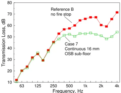
Case 7: Reference B with Continuous 15.9 mm OSB Sub-floor ...30
Case 8: (Retro-fit for Case 7) 15.9 mm Thick OSB Underlay ...34
Case 9: (Retro-fit for Case 7) Floating Floor System...38
Case 10: Reference B, No Fire Stop...40
Case 11: Reference B with Continuous 15.9 mm Plywood Sub-floor…………..44
Case 12: Continuous 15.9 mm OSB with non-load bearing party wall………….46
Discussion of Results ...48
Conclusions ...58
References ...61
Appendices:
Appendix A: Detailed Analysis of Cases 1-12
Appendix B: Reference A-B Sound Insulation with Basic Party Wall Construction
Appendix C: Analysis of Flanking Transmission Between Rooms B and D
Appendix D: Determination of Flanking Paths for Case 7 AB Sound Insulation with Basic Party Wall Construction
This report presents results of the sound transmission part of a research project to examine the sound and fire resistance of
wall/floor junctions intended for multi-family residential buildings. These constructions must satisfy National Building Code (NBCC) requirements for both noise control and fire resistance. Some junction designs control fire, but significantly increase the
transmission of noise. The objective of this project was to identify details that simultaneously provide good sound and fire resistance. This part of the project, titled “Flanking Transmission at Joints in
Multi-Family Dwellings Phase I: Transmission Via Fire Stops”,
was supported by a consortium that included Canada Mortgage and Housing Corporation, Forintek Canada, Gypsum Manufacturers of Canada, Institute for Research in Construction of the National Research Council Canada, New Home Warranty programs of Ontario, Alberta, British Columbia and the Yukon, Ontario
Ministry of Housing, Owens Corning Fiberglas Canada Inc., Roxul Inc., and the Canadian Home Builders’ Association.
These partners both supported the project financially and sent representatives to meet periodically as a Steering Committee, to evaluate results and select specimens for subsequent study. The measurements and analysis were performed in the Acoustics Laboratory of the Institute for Research in Construction at the National Research Council Canada.
The study focused on wood-framed construction, specifically the junction between a wood joist floor and a separating wall with two rows of 38 x 89 mm wood studs. These were examined for
construction details typical of both row-housing and small
apartment buildings. The floor joists were supported on the party wall for all but one of the specimens selected. While it is
recognized that other constructions may have similar or worse problems from a noise-control perspective, this combination was identified by the steering committee as the first priority when including fire safety.
The associated study of fire resistance of fire stop materials and wall/floor junction details has been conducted, and is reported separately1.
This report investigates how five commonly used fire control solutions for the floor/wall junction change (and in some cases
approaches to remedy, or at least reduce, the effect of noise transmission via fire stop constructions.
For all of these constructions, the report presents basic construction descriptions and the results of “standard” acoustical measurements of the sound insulation between the rooms in the test setup.
Appendix A presents more detailed analyses of the sound transmission for selected cases where flanking was significant. This report also provides:
• acoustical rank ordering of the fire stop techniques;
• limiting sound insulation for the fire stop techniques in the measured assemblies;
• identification of dominant flanking paths for supported floor ceiling assemblies;
• discussion of additional factors that are likely to control flanking transmission.
Flanking transmission is transmission of sound energy from one room to another by any path other than directly through the nominally separating wall or floor.
Flanking paths exist in all constructions regardless of type and design. It will be shown, however, that the amount of flanking transmission can be controlled, at least to some extent, by the use of suitable construction details.
Flanking transmission is part of the reason why walls or floors tested in buildings usually exhibit significantly worse performance than the nominally identical wall or floor assembly measured under the “no flanking” laboratory conditions of ASTM E90.
ASTM standards, which provide the technical basis for noise control provisions in the building codes of Canada and the USA, focus on two aspects of sound insulation.
• Sound transmission through a specific construction, such as the wall or floor separating two rooms, is the focus of ASTM E902 (laboratory tests); ASTM E3363 is the field equivalent.
Flanking Transmission: Definition and Significance
class (STC) for laboratory data, or FSTC for field data. Basically, this tells what fraction of the sound energy is transmitted through a given wall or floor construction.
• Sound insulation between two rooms is a second focus of ASTM E336. By fitting the STC contour to the measured noise reduction between two spaces, one obtains the noise isolation
class (NIC). The normalized version of this (adjusted to a
standardized sound decay rate, typical of furnished rooms) is the NNIC. For a performance-oriented building code, it is arguable that objectives should be expressed in terms of NIC or NNIC. Occupants do not care what noise reduction is provided by the nominally separating floor or wall – they care about overall noise reduction, no matter how noise gets from one dwelling to another.
ASTM does not provide a term to describe performance of
constructions explicitly including flanking transmission around the nominal separation.
Since this study focuses on sound insulation changes due to flanking transmission at floor/wall junctions, we use a minor extension of ASTM terminology. We followed the lead of international standard ISO 1405, which defines apparent sound reduction index for this purpose.
Apparent field transmission loss, and apparent FSTC, describe
ASTM E336 results where flanking is included. To emphasize that flanking is the focus, “apparent” is also added to describe impact transmission. Technical details about determination of these ratings are given in Appendix A, with the detailed analysis of results.
It is the apparent sound insulation (including the direct path plus all the flanking paths) that determines the perceived degree of sound insulation between rooms - not just the STC of the wall or floor nominally separating the rooms.
The Table 1 shows four flanking scenarios to illustrate how flanking transmission influences the apparent STC and must be considered when selecting a wall or floor assembly to meet a design goal.
Definition of Apparent Sound Insulation
and flanking paths, the apparent STC will be 3 lower than the separating wall’s STC.
In this illustration, improving the separating wall to STC 60 or STC 65 has little impact on the apparent sound insulation. Unless the flanking path transmits less sound power (higher transmission loss or STC), the apparent STC cannot exceed 55. If the flanking transmission were worse (as it may be in typical buildings), the apparent STC would be limited to even lower values. Very simply, the apparent sound insulation is determined by the weakest link, be it the flanking path or the nominal separating element.
Generalizing, it is possible for flanking paths to completely control the apparent sound insulation, regardless of the performance of the nominally separating wall or floor. This impact of flanking transmission becomes more significant when high sound insulation is
required. Table 1:
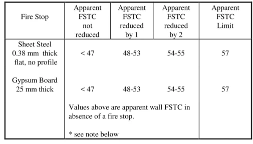
Illustration where flanking paths transmit the same sound power as a wall of STC 55. The effects of flanking reduce apparent insulation more as the sound insulation of the separating wall improves. Apparent STC due to flanking Separating Wall Apparent STC including all paths Importance of Flanking STC 55 STC 50 49 Minor STC 55 STC 55 52 Significant STC 55 STC 60 54 near-dominant STC 55 STC 65 55 Dominant
Note that if the flanking path transmitted more sound power, the apparent STC would be even lower in each case.
Figure 1 shows a sketch of the facility that was designed and constructed in 1992 for the measurement of flanking transmission in lightweight framed multi-family constructions.
A B C D Facade Wall H W L Party Partitions
The wall and floor specimens divide the space into four rooms (labeled A, B, C, D in the drawing). Dimensions of the four rooms are given in the table below.
Room Volume (m3) Length (m) Width (m) Height (m) A 50.7 4.60 4.54 2.43 B 45.3 4.11 4.54 2.43 C 40.0 4.66 4.38 2.07 D 35.3 3.96 4.38 2.07
The permanent part of the facility (roof, end walls, foundation floor, and back wall) are constructed of heavy materials and are resiliently isolated from each other and from structural support members, with vibration breaks in the permanent surfaces where the specimens are installed. There is also an experimental facade wall covering the front face of the facility, but this was deliberately isolated from the specimens for this study.
In such a facility, specific construction changes can be
systematically introduced so that resulting changes in the sound insulation performance of the experimental surfaces can be accurately determined.
Measurement & Facility Details
Figure 1: Schematic drawing of the flanking facility showing wall and floor specimens in gray. Some possible flanking paths are shown by arrows.
Measurements were made between each pair of rooms, including the diagonals, to determine the effect of the different fire stops and retro-fit constructions implemented in a series of specimens. The project was structured using reference specimens which did not have fire stopping (and hence did not meet the intent of the 1990 or 1995 NBCC). These specimens provided a point of reference to determine the change in sound transmission due to the various fire stop constructions.
For reasons discussed below, two such reference specimens were used. These were the first and last specimens of the study, and designated as Reference A and Reference B, respectively.
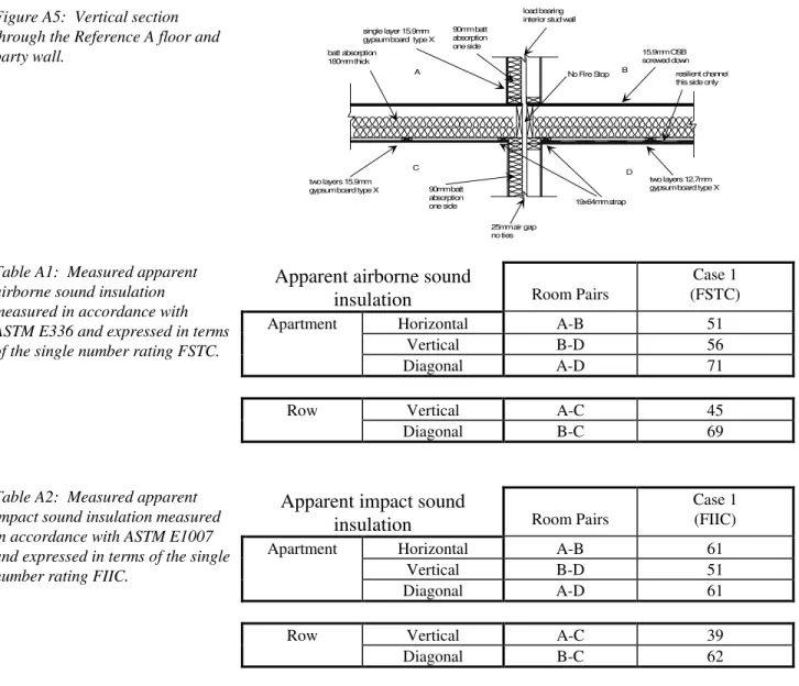
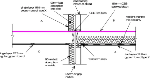
Figure 2 shows the vertical section through the floor and party wall of Reference A. Construction details of the floor and wall framing are discussed more fully later in the report. Note that both floors are fire-rated, but only the floor between rooms B and D has resilient metal channels (which are necessary to provide the sound insulation required between apartments).
A B
C D
No Fire Stop load bearing
interior stud wall 90mm batt absorption one side batt absorption 180mm thick single layer 15.9mm gypsum board type X
two layers 15.9mm
gypsum board type X 90mm batt
absorption one side 25mm air gap no ties 15.9mm OSB screwed down resilient channel this side only
two layers 12.7mm gypsum board type X 19x64mm strap
Acoustical performance of this first case was evaluated in considerable detail, to provide the baseline for subsequent specimens.
SPECIMEN SERIES
Figure 2: Vertical section through the floor and party wall of Reference Case A.
Reference Case A was then modified by addition of the following fire stop constructions:
Case 2: Additional cavity absorption in the wall space such that
the width of the concealed wall space does not exceed 25 mm (1995 NBCC 9.10.15.2.2.a)6. With this condition met, an
explicit fire stop is not required.
Case 3: Gypsum board 25 mm thick installed vertically in the nominal 25 mm space between joist headers at the wall/floor joint. In Case 3, the floor/ceiling assembly is fire rated. This detail satisfies the criteria for location (9.10.15.2.1) and material (9.10.15.3.1.c) for fire stops.
At this stage, two significant changes were made in the approach to evaluating the fire stop constructions:
It was decided to include measurements using a substantially better party wall. Figure 3(a) and (b) show construction details of the basic and superior party wall. Both of these wall constructions were used with most of the later cases.
At the same time, the Steering Committee recommended changing the floor
construction between rooms A and C, to provide data more relevant to row housing. Floor B-D would suit apartment style constructions. This meant that
Reference A was not a fully valid reference for subsequent measurements. To provide a baseline reference to which subsequent measurements could be legitimately compared, another baseline case without a fire stop (Reference B) was measured at the end of the series. It is described in detail later.
Figure 3(a): Construction details of the “basic” party wall, which in laboratory testing in the absence of flanking is rated at STC 55. 15.9 mm type X gypsum board 90 mm batt absorption 38 x 89 mm wood studs 400 mm o.c.
Figure 3(b): The “superior” party wall, which in laboratory testing in the absence of flanking is rated at STC 67. 2 x 15.9 mm type X gypsum board 90 mm batt absorption 38 x 89 mm wood studs 400 mm o.c.
Other fire stop cases were then tested:
Case 4: Gypsum board 25 mm thick installed vertically in the nominal 25 mm space between joist headers at the wall/floor joint. The A-C floor/ceiling assembly is not fire rated. This detail satisfies the criteria for location (9.10.15.2.1) and material (9.10.15.3.1.c) for fire stops. Tested with basic and superior party wall. Use Reference B as baseline case.
Case 5: Semi-rigid batt material installed vertically in the nominal 25 mm space between joist headers at the wall/floor joint. The A-C floor/ceiling assembly is not fire rated. This detail satisfies the criterion for location (9.10.15.2.1) for fire stops, but semi-rigid batt material is not listed (9.10.15.3.1) as an acceptable material. However, semi-rigid materials were tested in the fire component of this project and found to comply with 9.10.15.3.g as interpreted by the Steering Committee of this consortium. Use Reference B as baseline case.
Case 6: 0.38 mm sheet steel (without profile) installed horizontally under the sole plates of the party wall. The A-C floor/ceiling assembly is not fire rated. This detail satisfies the criteria for location (9.10.15.2.1) and material (9.10.15.3.1.a) for fire stops. Tested with basic and superior party wall. Use Reference B as baseline case.
Case 7: 15.9 mm thick OSB continuous under the sole plates of the party wall. The A-C floor/ceiling assembly is not fire rated. This detail satisfies the criteria for location (9.10.15.2.1) and material (9.10.15.3.1.d) for fire stops. Tested with basic and superior party wall. Use Reference B as baseline case. Case 11: 15.9 mm thick Plywood continuous under the sole plates of the party wall. The A-C floor/ceiling assembly is not fire rated. This detail satisfies the criteria for location
(9.10.15.2.1) and material (9.10.15.3.1.d) for fire stops. Tested with the superior party wall. Use Reference B as baseline case. Case 12: 15.9 mm thick OSB continuous under the sole plates of the party wall. In this case the party wall is non-load bearing and the joists are laid parallel to the party wall. The A-C floor/ceiling assembly is not fire rated. This detail satisfies the criteria for location (9.10.15.2.1) and material (9.10.15.3.1.d)
Two constructions suitable for improving sound insulation of existing constructions, to compensate for obvious flanking, were also investigated. These are called retro-fits (though similar measures could be used in new construction) and were applied to Case 7, the continuous OSB sub-floor which will be shown to be one of the most serious cases of flanking by a fire stop:
Case 8: Underlay, 15.9 mm thick OSB placed on top of the existing 15.9 mm thick OSB sub-floor which is continuous under the party wall (i.e., Case 7). Tested with basic and superior party walls. Use Reference B as a baseline case. Case 9: Floating Floor System placed on top of the existing 15.9 mm thick OSB sub-floor which is continuous under the party wall (i.e., Case 7). Tested with superior party wall. Use Reference B as a baseline case.
Reference B was similar to Reference A in that it had no fire stop, but the floor between rooms A and C was constructed to match all the specimens after Case 3. This change of floor/ceiling
construction was made to obtain data relevant to row housing, in addition to apartment style constructions represented by floor B-D. The changes involved removing the batt insulation from between the joists, and changing the gypsum board on the ceiling of room C from two layers of 15.9 mm Type X gypsum board to one layer of 12.7 mm regular gypsum board. With these changes, floor A-C was considered representative of row housing (where the floor between levels within a dwelling does not require either STC 50 (minimum) or a fire rating). By contrast, floor B-D satisfies both the sound and fire resistance requirements of the Building Code for a separation between adjacent dwellings, as would be expected in an apartment building.
The floor modifications were not expected to significantly change the horizontal transmission between A and B (as was later
confirmed by the results). However, they should highlight any difference in the effect of fire stops on vertical or diagonal transmission in row housing (A-C and B-C) versus apartments (B-D and A-D).
Unfortunately, for horizontal transmission between the lower rooms (C-D), the construction is a mix of apartment and row housing details. For this reason, the C-D data were omitted from the tables in the summary of data in the main report. In practice, it was found that there was very little variation in the apparent airborne sound insulation between rooms C and D due to changes in the fire stop, the ceiling of room C, or the party wall between rooms A and B.
The specimens described in the preceding pages have many details in common. Some of those, such as the two constructions for the party wall between rooms A and B, have been described above. Two other key features - the framing of the floor systems and the junction between the party wall and the facade wall are detailed here.
Figure 4 (at left) shows the plan section at the intersection of the party and facade walls. This detail is common to all rooms. Because these tests were designed to
establish the effect of individual fire stops at the wall/floor joint, the facade wall joint was chosen to minimize its effect as a flanking path between rooms, and the finish surface of the facade wall (on the side toward the test rooms) was purposely made massive and was resiliently mounted. The facade wall was unchanged throughout the series.
The basic framing of the floors was
unchanged throughout the series, and differed between rooms only in the span. The gypsum board ceiling in Room D was attached with resilient metal channels, but that in Room C was screwed directly to the furring strips. The type and number of layers of gypsum board changed (as detailed in the following descriptions of each sample).
Figure 5 (at left) shows the reflected plan view of the floor framing typical of rooms A and B for all specimens. At one end, the joists were supported on the party wall, and at the other end on isolated supports at the end wall of the facility. Where resilient channels were used in Room D, they were at right angles to the strapping.
Common Details load bearing party wall 38x89mm studs 400mm o.c. 90mm batt insulation 38x140mm wood studs 400mm o.c. 15.9mm Type X gypsum board batt insulation 140mm thick exterior cladding
(not part of the specimen)
two layers 15.9mm Type X gypsum board resilient channel 600mm o.c. facade wall Figure 4 89x235mm joists 400mm o.c. 19x64mm strap 600mm 600mm 600mm 600mm 600mm 600mm 600mm 90mm j i t h d t t ll bridging and strapping Figure 5
A description of the construction details is provided for each specimen tested, along with the apparent FSTC and apparent FIIC ratings. The ratings given are determined from the average of the forward and reverse measurements between each room pair.
The results for each specimen are divided into two tables reflecting the division into results appropriate to row housing and results appropriate to apartments.
Unfortunately the hybrid floor construction, designed to allow the study of both row housing and apartment style constructions at the same time, is a compromise. The result is that the A-D diagonal case is not quite as good as would be expected for an apartment construction, the floor of room A is too light and lacks batt
insulation. On the other hand, the B-C diagonal case is better than would be expected for a row housing construction, the floor of room B is too heavy and has batt insulation. In the context of this report, the impact of this compromise is likely to be small because the diagonal measurements are used only in qualitative assessments of flanking paths. In practical terms this is a minor concern since in all cases the diagonal provided an apparent FSTC over 60. Detailed discussions of the results, including determination of flanking paths and inter-specimen comparisons, have been included as appendices to the main report.
SPECIMEN DETAILS AND RESULTS
Case 1: Reference A, No fire stop Basic A-B party wall
Purpose:
To establish a reference case to which specimens having a fire stop at the joint can be compared. If there is no difference between the reference case and the cases with the fire stop, then the presence of the fire stop has no effect acoustically.
The floor between rooms A and C was similar to the floor between B and D with the primary difference being the absence of resilient channels. This provides information regarding the effects of resilient channels on the flanking transmission paths.
Party Wall:
Double wood stud load-bearing wall having separate head and sole plates (nominal 25 mm separation between frames), double head plate, 90 mm batt insulation material filling one side of the wall cavity, finished with a single layer of 15.9 mm Type X
gypsum board either side. Gypsum board installed vertically and fastened with 36 mmor longer screws placed 400 mm o.c.
Floor:
15.9 mm OSB floor decking fastened with 51 mm or longer #10 straight shank wood screws placed 150 mm o.c. at edges and 300 mm o.c. in the field, 38x235 mm wood joists 400 mm o.c., 180 mm of batt insulation material (2 layers of 90 mm batt material were used), bridging and strapping; 19x64 mm strapping 600 mm o.c. used as furring strips, 19x64 mm bracing no more than 2100 mm o.c. located at strapping points (see Figure 5).
Room C: two layers of 15.9 mm Type X gypsum board placed directly on the wood furring. The base layer was attached with 36 mmor longer screws placed 300 mm o.c. at the edges and 600 mm o.c. in the field. The top layer was installed with 52 mm or longer screws placed 300 mm o.c. at the edges and in the field.
Room D: generic resilient channels 600 mm o.c., placed perpendicular to the strapping, two layers of 12.7 mm Type X gypsum board. The base layer was attached with 36 mmor longer screws placed 300 mm o.c. at the edges and 600 mm o.c. in the field. The top layer was installed with 52 mm or longer screws placed 300 mm o.c. at the edges and in the field.
Floor/Wall Intersection:
Load bearing party wall with the joists perpendicular to the party wall, single joist header, no batt insulation in the nominal 25x365 mm cavity formed by the joist headers and the wall plates.
Facade Wall:
Case 1:
Reference A, No fire stop
Basic A-B party wall
A B
C
D No Fire Stop load bearing
interior stud wall 90mm batt absorption one side batt absorption 180mm thick single layer 15.9mm gypsum board type X
two layers 15.9mm
gypsum board type X 90mm batt absorption one side 25mm air gap no ties 15.9mm OSB screwed down resilient channel this side only
two layers 12.7mm gypsum board type X 19x64mm strap
Figure 6
Apparent airborne
sound insulation
Room PairsReference A (FSTC)
Apartment Horizontal A-B 51
Vertical B-D 56
Diagonal A-D 71
Direct applied Vertical A-C 45
ceiling Diagonal B-C 69
Apparent impact
sound insulation
Room PairsReference A (FIIC)
Apartment Horizontal A-B 61
Vertical B-D 51
Diagonal A-D 61
Direct applied Vertical A-C 39
Case 2: Reference A with additional cavity absorption Basic A-B party wall
Purpose:
This assembly satisfies the intent of the NBCC (1995: 9.10.15.2.2.a) since the cavity is 25 mm or less in width. This technique is applicable to both row and apartment type constructions.
The floor between rooms A and C was similar to the floor between B and D, with the primary difference being the absence of resilient channels. This provides information regarding the effects of resilient channels on the flanking transmission paths.
Note: That if the nominal 25 mm separation between frame work was completely filled with absorption there would be no appreciable difference in the sound insulation and it would satisfy the intent of NBCC (1995: 9.10.15.1.2.2.d).
Party Wall:
Double wood stud load-bearing wall having separate head and sole plates (nominal 25 mm separation between frames), double head plate, 90 mm batt insulation material filling both sides of the wall cavity, finished with a single layer of 15.9 mm Type X gypsum board either side. Gypsum board installed vertically and fastened with 36 mmor longer screws placed 400 mm o.c.
Floor:
15.9 mm OSB floor decking fastened with 51 mm or longer #10 straight shank wood screws placed 150 mm o.c. at edges and 300 mm o.c. in the field, 38x235 mm wood joists 400 mm o.c., 180 mm of batt insulation material (2 layers of 90 mm batt material were used), bridging and strapping; 19x64 mm strapping 600 mm o.c. used as furring strips, 19x64 mm bracing no more than 2100 mm o.c. located at strapping points (see Figure 5).
Room C: two layers of 15.9 mm Type X gypsum board placed directly on the wood furring. The base layer was attached with 36 mmor longer screws placed 300 mm o.c. at the edges and 600 mm o.c. in the field. The top layer was installed with 52 mm (2 ¼”) or longer screws placed 300 mm o.c. at the edges and in the field.
Room D: generic resilient channels 600 mm o.c., placed perpendicular to the strapping, two layers of 12.7 mm Type X gypsum board. The base layer was attached with 36 mmor longer screws placed 300 mm o.c. at the edges and 600 mm o.c. in the field. The top layer was installed with 52 mm or longer screws placed 300 mm o.c. at the edges and in the field.
Floor/Wall Intersection:
Load bearing party wall with the joists perpendicular to the party wall, single joist header, no batt insulation in the nominal 25x365 mm cavity formed by the joist headers and the wall plates.
Facade Wall:
Case 2:
Reference A with additional cavity absorption
Basic A-B party wall
A B
C D
batt absorption 180mm thick
single layer 15.9mm gypsum board type X
90mm batt absorption both sides 90mm batt absorption both sides load bearing interior stud wall
15.9mm OSB screwed down
resilient channel this side only
two layers 12.7mm gypsum board type X 19x64mm strap
25mm air gap no ties two layers 15.9mm
gypsum board type X
Figure 7
Apparent airborne
sound insulation
Room PairsCase: 2 with basic wall
(FSTC)
Change re Reference A
Apartment Horizontal A-B 56 +5
Vertical B-D 56 0
Diagonal A-D 75 +1
Direct applied Vertical A-C 46 +1
ceiling Diagonal B-C 73 +4
Apparent impact
sound insulation
Room PairsCase: 2 with basic wall
(FIIC)
Change re Reference A
Apartment Horizontal A-B 64 + 3
Vertical B-D 50 -1
Diagonal A-D 71 +10
Direct applied Vertical A-C 39 0
Case 3: Reference A with 25 mm thick gypsum board at joint Basic A-B party wall
Purpose:
To establish the effect of introducing a 25 mm gypsum board fire stop in apartment type constructions.
The floor between rooms A and C was similar to the floor between B and D with the primary difference being the absence of resilient channels. This provides information regarding the effects of resilient channels on the flanking transmission paths.
Party Wall:
Double wood stud load-bearing wall having separate head and sole plates (nominal 25 mm separation between frames), double head plate, 90 mm batt insulation material filling one side of the wall cavity, finished with a single layer of 15.9 mm Type X
gypsum board either side. Gypsum board installed vertically and fastened with 36 mmor longer screws placed 400 mm o.c.
Floor:
15.9 mm OSB floor decking fastened with 51 mm or longer #10 straight shank wood screws placed 150 mm o.c. at edges and 300 mm o.c. in the field, 38x235 mm wood joists 400 mm o.c., 180 mm of batt insulation material (2 layers of 90 mm batt material were used), bridging and strapping; 19x64 mm strapping 600 mm o.c. used as furring strips, 19x64 mm bracing no more than 2100 mm o.c. located at strapping points (see Figure 5).
Room C: two layers of 15.9 mm Type X gypsum board placed directly on the wood furring. The base layer was attached with 36 mmor longer screws placed 300 mm o.c. at the edges and 600 mm o.c. in the field. The top layer was installed with 52 mm or longer screws placed 300 mm o.c. at the edges and in the field.
Room D: generic resilient channels 600 mm o.c., placed perpendicular to the strapping, two layers of 12.7 mm Type X gypsum board. The base layer was attached with 36 mmor longer screws placed 300 mm o.c. at the edges and 600 mm o.c. in the field. The top layer was installed with 52 mm or longer screws placed 300 mm o.c. at the edges and in the field.
Floor/Wall Intersection:
Load bearing party wall with the joists perpendicular to the party wall, single joist header, two layers of 12.7 mm Type X gypsum board (nominal width 600 mm) placed in compression between the joist headers and the wall plates. A single drywall screw in the top corners of each sheet held the material in place.
Facade Wall:
Case 3:
Reference A with 25 mm thick gypsum board at joint
Basic A-B party wall
two layers 12.7mm gypsum board type X
15.9mm OSB screwed down 19x64mm strap batt absorption 180mm thick batt absorption 90mm thick one side load bearing interior stud wall
25mm air gap no ties
2 layers 12.7 mm Type X gypsum board or 25mm coreboard (gypsum board) A B C D single layer 15.9mm
gypsum board type X
resilient channel this side only
two layers 15.9mm gypsum board type X
Figure 8
Apparent airborne
sound insulation
Room PairsCase: 3 with basic wall
(FSTC)
Change re Reference A
Apartment Horizontal A-B 51 0
Vertical B-D 57 +1
Diagonal A-D 66 -5
Direct applied Vertical A-C 45 0
ceiling Diagonal B-C 64 -5
Apparent impact
sound insulation
Room PairsCase: 3 with basic wall
(FIIC)
Change re Reference A
Apartment Horizontal A-B 55 -6
Vertical B-D 52 +1
Case 4: Reference B with 25 mm gypsum board at joint Basic A-B party wall
Purpose:
To establish the effect of introducing a 25 mm gypsum board fire stop.
The floor between rooms A and C is characteristic of row housing type constructions, while the floor between rooms B and D is characteristic of apartment type constructions. The construction is similar to what might be found in stacked constructions where the apartments are offset by one floor. This construction permits study of the different flanking transmission paths which are present in the two types of construction. Party Wall:
Double wood stud load-bearing wall having separate head and sole plates (nominal 25 mm separation between frames), double head plate, 90 mm batt insulation material filling one side of the wall cavity, finished with a single layer of 15.9 mm Type X
gypsum board either side. Gypsum board installed vertically and fastened with 36 mmor longer screws placed 400 mm o.c.
Floor:
15.9 mm OSB floor decking fastened with 51 mm or longer #10 straight shank wood screws placed 150 mm o.c. at edges and 300 mm o.c. in the field, 38x235 mm wood joists 400 mm o.c., bridging and strapping; 19x64 mm strapping 600 mm o.c. used as furring strips, 19x64 mm bracing no more than 2100 mm o.c. located at strapping points (see Figure 5).
Room C: single layer of 12.7 mm regular gypsum board placed directly on the wood furring, (no cavity absorption). The gypsum board was installed with 36 mmor longer screws placed 300 mm o.c. at the edges and in the field.
Room D: 180 mm of batt insulation material (2 layers of 90 mm batt material were used), generic resilient channels 600 mm o.c., placed perpendicular to the strapping, two layers of 12.7 mm Type X gypsum board. The base layer was attached with 36 mmor longer screws placed 300 mm o.c. at the edges and 600 mm o.c. in the field. The top layer was installed with 52 mm or longer screws placed 300 mm o.c. at the edges and in the field.
Floor/Wall Intersection:
Load bearing party wall with the joists perpendicular to the party wall, single joist header, two layers of 12.7 mm Type X gypsum board (nominal width 600 mm) placed in compression between the joist headers. A single drywall screw in the top corners of each sheet held the material in place.
Facade Wall:
Case 4:
Reference B with 25 mm thick gypsum board at joint
Basic A-B party wall
Row construction in floor A-C
2 layers 12.7 mm Type X gypsum board or 25mm coreboard (gypsum board) B C D single layer 15.9mm
gypsum board type X
90mm batt absorption one side 90mm batt absorption one side load bearing
interior stud wall 15.9mm OSB screwed down
resilient channel this side only
two layers 12.7mm gypsum board type X 19x64mm strap
25mm air gap no ties single layer 12.7mm
regular gypsum board
A
Figure 9
Apparent airborne
sound insulation
RoomPairsCase: 4 with basic wall
(FSTC)
Change re Reference B with basic wall
Change re Reference A
Apartment Horizontal A-B 50 0 -1
Vertical B-D 57 +2 +1
Diagonal A-D 65 -5 -6
Row Vertical A-C n/a n/a n/a
Diagonal B-C 61 -5 -8
Apparent impact
sound insulation
RoomPairsCase: 4 with basic wall
(FIIC)
Change re Reference B with basic wall
Change re Reference A
Apartment Horizontal A-B 52 -9 -9
Vertical B-D 51 +1 0
Diagonal A-D 57 n/a -4
Row Vertical A-C n/a n/a n/a
Case 4: Reference B with 25 mm thick gypsum board at joint Superior A-B party wall
Purpose:
To establish the effect of introducing a 25 mm gypsum board fire stop.
The floor between rooms A and C is characteristic of row housing type constructions, while the floor between rooms B and D is characteristic of apartment type constructions. The construction is similar to what might be found in stacked constructions where the apartments are offset by one floor. This construction permits study of the different flanking transmission paths which are present in the two types of construction. The superior A-B wall will establish the limiting sound insulation for the construction with this type of fire stop.
Superior Party Wall:
Double wood stud load-bearing wall having separate head and sole plates (nominal 25 mm separation between frames), double head plate, 90 mm batt insulation material filling both sides of the wall cavity, finished with two layers of 15.9 mm Type X gypsum board installed vertically on either side with staggered joints. The base layer was
attached with 36 mmor longer screws placed 400 mm o.c. The top layer was installed with 52 mm or longer screws placed 300 mm o.c. at the edges and in the field.
Floor:
15.9 mm OSB floor decking fastened with 51 mm or longer #10 straight shank wood screws placed 150 mm o.c. at edges and 300 mm o.c. in the field, 38x235 mm wood joists 400 mm o.c., bridging and strapping; 19x64 mm strapping 600 mm o.c. used as furring strips, 19x64 mm bracing no more than 2100 mm o.c. located at strapping points (see Figure 5).
Room C: single layer of 12.7 mm regular gypsum board placed directly on the wood furring (no cavity absorption). The gypsum board was installed with 36 mmor longer screws placed 300 mm o.c. at the edges and in the field.
Room D: 180 mm of batt insulation material (2 layers of 90 mm batt material were used), generic resilient channels 600 mm o.c., placed perpendicular to the strapping, two layers of 12.7 mm Type X gypsum board. The base layer was attached with 36 mmor longer screws placed 300 mm o.c. at the edges and 600 mm o.c. in the field. The top layer was installed with 52 mm or longer screws placed 300 mm o.c. at the edges and in the field.
Floor/Wall Intersection:
Load bearing party wall with the joists perpendicular to the party wall, single joist header, two layers of 12.7 mm Type X gypsum board (nominal width 600 mm) placed in compression between the joist headers. A single drywall screw in the top corners of each sheet held the material in place.
Facade Wall:
Case 4:
Reference B with 25 mm thick gypsum board at joint
Superior A-B party wall
two layers 15.9mm gypsum board type X
15.9mm OSB screwed down 19x64mm strap batt absorption 90mm thick one side load bearing interior stud wall
25mm air gap no ties
2 layers 12.7 mm Type X gypsum board or 25mm coreboard (gypsum board) A B C D two layers 15.9mm
gypsum board type X
both sides resilient channel
this side only
single layer 12.7mm regular gypsum board
batt absorption 90mm thick both sides
Figure 10
Apparent airborne
sound insulation
Room PairsCase: 4 with superior wall
(FSTC)
Change re Reference B with superior wall
Apartment Horizontal A-B 57 -9
Vertical B-D n/a n/a
Diagonal A-D n/a n/a
Row Vertical A-C n/a n/a
Diagonal B-C 64 -6
Apparent impact
sound insulation
Room PairsCase: 4 with superior wall
(FIIC)
Change re Reference B with superior wall
Apartment Horizontal A-B 57 -9
Vertical B-D n/a n/a
Diagonal A-D n/a n/a
Row Vertical A-C n/a n/a
Case 5: Reference B with 25 mm semi-rigid insulation Basic A-B party wall
Purpose:
To establish the effect of introducing a 25 mm semi-rigid batt (glass or rock fibre) fire stop. The semi-rigid material had a nominal thickness of 25 mm and a nominal surface density of 5 lbs per cubic foot or 80 kg per cubic meter.
The floor between rooms A and C is characteristic of row housing type constructions, while the floor between rooms B and D is characteristic of apartment type constructions. The construction is similar to what might be found in stacked constructions where the apartments are offset by one floor. This construction permits study of the different flanking transmission paths which are present in the two types of construction. Party Wall:
Double wood stud load-bearing wall having separate head and sole plates (nominal 25 mm separation between frames), double head plate, 90 mm batt insulation material filling one side of the wall cavity, finished with a single layer of 15.9 mm Type X
gypsum board either side. Gypsum board installed vertically and fastened with 36 mmor longer screws placed 400 mm o.c.
Floor:
15.9 mm OSB floor decking fastened with 51 mm or longer #10 straight shank wood screws placed 150 mm o.c. at edges and 300 mm o.c. in the field, 38x235 mm wood joists 400 mm o.c., bridging and strapping; 19x64 mm strapping 600 mm o.c. used as furring strips, 19x64 mm bracing no more than 2100 mm o.c. located at strapping points (see Figure 5).
Room C: single layer of 12.7 mm regular gypsum board placed directly on the wood furring (no cavity absorption). The gypsum board was installed with 36 mmor longer screws placed 300 mm o.c. at the edges and in the field.
Room D: 180 mm of batt insulation material (2 layers of 90 mm batt material were used), generic resilient channels 600 mm o.c., placed perpendicular to the strapping, two layers of 12.7 mm Type X gypsum board. The base layer was attached with 36 mmor longer screws placed 300 mm o.c. at the edges and 600 mm o.c. in the field. The top layer was installed with 52 mm or longer screws placed 300 mm o.c. at the edges and in the field.
Floor/Wall Intersection:
Load bearing party wall with the joists perpendicular to the party wall, single joist header, single layer of 25 mm thick semi-rigid batt material (nominal width 600 mm) placed in compression between the joist headers and the wall plates. A single drywall screw in the top corners of each batt held the material in place.
Facade Wall:
Case 5:
Reference B with 25 mm semi-rigid batt
Basic A-B party wall
A B C D semi-rigid material single layer 15.9mm
gypsum board type X
90mm batt absorption one side 90mm batt absorption one side load bearing
interior stud wall 15.9mm OSB screwed down
resilient channel this side only
two layers 12.7mm gypsum board type X 19x64mm strap
25mm air gap no ties single layer 12.7mm
regular gypsum board
Figure 11
Apparent airborne
sound insulation
RoomPairsCase: 5 with basic wall
(FSTC)
Change re Reference B with basic wall
Change re Reference A
Apartment Horizontal A-B 52 +2 +1
Vertical B-D 57 +2 +1
Diagonal A-D 70 0 -1
Row Vertical A-C 40 0 n/a
Diagonal B-C 66 0 n/a
Apparent impact
sound insulation
RoomPairsCase: 5 with basic wall
(FIIC)
Change re Reference B with basic wall
Change re Reference A
Apartment Horizontal A-B 59 -2 -2
Vertical B-D 51 +1 0
Diagonal A-D 59 n/a -2
Row Vertical A-C 35 +2 n/a
Case 6: Reference B with 0.38 mm sheet steel (30 Ga.) Basic A-B party wall
Purpose:
To establish the effect of introducing a 0.38 mm sheet steel fire stop.
The floor between rooms A and C is characteristic of row housing type constructions, while the floor between rooms B and D is characteristic of apartment type constructions. The construction is similar to what might be found in stacked constructions where the apartments are offset by one floor. This construction permits study of the different flanking transmission paths which are present in the two types of construction. Party Wall:
Double wood stud load-bearing wall having separate head and sole plates (nominal 25 mm separation between frames), double head plate, 90 mm batt insulation material filling one side of the wall cavity, finished with a single layer of 15.9 mm Type X
gypsum board either side. Gypsum board installed vertically and fastened with 36 mmor longer screws placed 400 mm o.c.
Floor:
15.9 mm OSB floor decking fastened with 51 mm or longer #10 straight shank wood screws placed 150 mm o.c. at edges and 300 mm o.c. in the field, 38x235 mm wood joists 400 mm o.c., bridging and strapping; 19x64 mm strapping 600 mm o.c. used as furring strips, 19x64 mm bracing no more than 2100 mm o.c. located at strapping points (see Figure 5).
Room C: single layer of 12.7 mm regular gypsum board placed directly on the wood furring (no cavity absorption). The gypsum board was installed with 36 mmor longer screws placed 300 mm o.c. at the edges and in the field.
Room D: 180 mm of batt insulation material (2 layers of 90 mm batt material were used), generic resilient channels 600 mm o.c., placed perpendicular to the strapping, two layers of 12.7 mm Type X gypsum board. The base layer was attached with 36 mmor longer screws placed 300 mm o.c. at the edges and 600 mm o.c. in the field. The top layer was installed with 52 mm or longer screws placed 300 mm o.c. at the edges and in the field.
Floor/Wall Intersection:
Load bearing party wall with the joists perpendicular to the party wall, single joist header, single layer of 30 gauge (0.38 mm thick) sheet steel (nominal width 200 mm) was placed under the sole plates of the upper party wall. The sheet steel was installed flat without a profile or crease. (See Figure A17 of Appendix A for fastening diagram.) Facade Wall:
Case 6:
Reference B with 0.38 mm sheet steel (30 Ga.)
Basic A-B party wall
A B
C D
0.38 mm sheet steel single layer 15.9mm
gypsum board type X
90mm batt absorption one side 90mm batt absorption one side load bearing
interior stud wall 15.9mm OSB screwed down
resilient channel this side only
two layers 12.7mm gypsum board type X 19x64mm strap
25mm air gap no ties single layer 12.7mm
regular gypsum board
Figure 12
Apparent airborne
sound insulation
RoomPairsCase: 6 with basic wall
(FSTC)
Change re Reference B with basic wall
Change re Reference A
Apartment Horizontal A-B 51 +1 0
Vertical B-D 56 +1 0
Diagonal A-D 69 -1 -2
Row Vertical A-C 41 +1 -4
Diagonal B-C 64 -2 -5
Apparent impact
sound insulation
RoomPairsCase: 6 with basic wall
(FIIC)
Change re Reference B with basic wall
Change re Reference A
Apartment Horizontal A-B 54 -7 -7
Vertical B-D 51 +1 0
Diagonal A-D n/a n/a n/a
Row Vertical A-C n/a n/a n/a
Case 6: Reference B with 0.38 mm sheet steel (30 Ga.) Superior A-B party wall
Purpose:
To establish the effect of introducing a 0.38 mm sheet steel fire stop.
The floor between rooms A and C is characteristic of row housing type constructions, while the floor between rooms B and D is characteristic of apartment type constructions. The construction is similar to what might be found in stacked constructions where the apartments are offset by one floor. This construction permits study of the different flanking transmission paths which are present in the two types of construction. The superior A-B wall will establish the limiting sound insulation for the construction with this type of fire stop.
Superior Party Wall:
Double wood stud load-bearing wall having separate head and sole plates (nominal 25 mm separation between frames), double head plate, 90 mm batt insulation material filling both sides of the wall cavity, finished with two layers of 15.9 mm Type X gypsum board installed vertically on either side with staggered joints. The base layer was
attached with 36 mmor longer screws placed 400 mm o.c. The top layer was installed with 52 mm or longer screws placed 300 mm o.c. at the edges and in the field.
Floor:
15.9 mm OSB floor decking fastened with 51 mm or longer #10 straight shank wood screws placed 150 mm o.c. at edges and 300 mm o.c. in the field, 38x235 mm wood joists 400 mm o.c., bridging and strapping; 19x64 mm strapping 600 mm o.c. used as furring strips, 19x64 mm bracing no more than 2100 mm o.c. located at strapping points (see Figure 5).
Room C: single layer of 12.7 mm regular gypsum board placed directly on the wood furring (no cavity absorption). The gypsum board was installed with 36 mmor longer screws placed 300 mm o.c. at the edges and in the field.
Room D: 180 mm of batt insulation material (2 layers of 90 mm batt material were used), generic resilient channels 600 mm o.c., placed perpendicular to the strapping, two layers of 12.7 mm Type X gypsum board. The base layer was attached with 36 mm(or longer screws placed 300 mm o.c. at the edges and 600 mm o.c. in the field. The top layer was installed with 52 mm or longer screws placed 300 mm o.c. at the edges and in the field.
Floor/Wall Intersection:
Load bearing party wall with the joists perpendicular to the party wall, single joist header, single layer of 30 gauge (0.38 mm thick) sheet steel (nominal width 200 mm) was placed under the sole plates of the upper party wall. The sheet steel was installed flat without a profile or crease. (See Figure A17 of Appendix A for fastening diagram.) Facade Wall:
Case 6:
Reference B with 0.38 mm sheet steel (30 Ga.)
Superior A-B party wall
A B
C D
0.38 mm sheet steel two layers 15.9mm
gypsum board type X both sides 90mm batt absorption both sides 90mm batt absorption one side load bearing
interior stud wall 15.9mm OSB screwed down
resilient channel this side only
two layers 12.7mm gypsum board type X 19x64mm strap
25mm air gap no ties single layer 12.7mm
regular gypsum board
Figure 13
Apparent airborne
sound insulation
Room PairsCase: 6 with superior wall
(FSTC)
Change re Reference B with superior wall
Apartment Horizontal A-B 57 -9
Vertical B-D 57 +2
Diagonal A-D n/a n/a
Row Vertical A-C n/a n/a
Diagonal B-C 65 -5
Apparent impact
sound insulation
Room PairsCase: 6 with superior wall
(FIIC)
Change re Reference B with superior wall
Apartment Horizontal A-B 55 -9
Vertical B-D n/a n/a
Diagonal A-D n/a n/a
Row Vertical A-C 38 +5
Case 7: Reference B with continuous 15.9 mm OSB sub-floor Basic A-B party wall
Purpose:
To establish the effect of introducing a 15.9 mm OSB fire stop by running the sub-floor under the upper party wall.
The floor between rooms A and C is characteristic of row housing type constructions, while the floor between rooms B and D is characteristic of apartment type constructions. The construction is similar to what might be found in stacked constructions where the apartments are offset by one floor. This construction permits study of the different flanking transmission paths which are present in the two types of construction. Party Wall:
Double wood stud load-bearing wall having separate head and sole plates (nominal 25 mm separation between frames), double head plate, 90 mm batt insulation material filling one side of the wall cavity, finished with a single layer of 15.9 mm Type X
gypsum board either side. Gypsum board installed vertically and fastened with 36 mmor longer screws placed 400 mm o.c.
Floor:
15.9 mm OSB floor decking fastened with 51 mm or longer #10 straight shank wood screws placed 150 mm o.c. at edges and 300 mm o.c. in the field, 38x235 mm wood joists 400 mm o.c., bridging and strapping; 9x64 mm strapping 600 mm o.c. used as furring strips, 19x64 mm bracing no more than 2100 mm o.c. located at strapping points (see Figure 5).
Room C: single layer of 12.7 mm regular gypsum board placed directly on the wood furring (no cavity absorption). The gypsum board was installed with 36 mmor longer screws placed 300 mm o.c. at the edges and in the field.
Room D: 180 mm of batt insulation material (2 layers of 90 mm batt material were used), generic resilient channels 600 mm o.c., placed perpendicular to the strapping, two layers of 12.7 mm Type X gypsum board. The base layer was attached with 36 mmor longer screws placed 300 mm o.c. at the edges and 600 mm o.c. in the field. The top layer was installed with 52 mm or longer screws placed 300 mm o.c. at the edges and in the field.
Floor/Wall Intersection:
Load bearing party wall with the joists perpendicular to the party wall, single joist header. The 15.9 mm thick OSB sub-floor was run under the party wall.
Facade Wall:
Case 7:
Reference B with continuous 15.9 mm OSB sub-floor
Basic A-B party wall
A B
C D
OSB Fire Stop single layer 15.9mm
gypsum board type X
90mm batt absorption one side 90mm batt absorption one side load bearing
interior stud wall 15.9mm OSB screwed down
resilient channel this side only
two layers 12.7mm gypsum board type X 19x64mm strap
25mm air gap no ties single layer 12.7mm
regular gypsum board
Figure 14
Apparent airborne
sound insulation
RoomPairsCase: 7 with basic wall
(FSTC)
Change re Reference B with basic wall
Change re Reference A
Apartment Horizontal A-B 50 0 -1
Vertical B-D 56 +1 0
Diagonal A-D 66 -4 -5
Row Vertical A-C 41 +1 n/a
Diagonal B-C 61 -5 n/a
Apparent impact
sound insulation
Room PairsCase: 7 with basic wall
(FIIC)
Change re Reference B with basic wall
Change re Reference A
Apartment Horizontal A-B 51 -10 -10
Vertical B-D 51 +1 0
Diagonal A-D 55 n/a -6
Row Vertical A-C n/a n/a n/a
Case 7: Reference B with continuous 15.9 mm OSB sub-floor Superior A-B party wall
Purpose:
To establish the effect of introducing a 15.9 OSB fire stop by running the sub-floor under the upper party wall.
The floor between rooms A and C is characteristic of row housing type constructions, while the floor between rooms B and D is characteristic of apartment type constructions. The construction is similar to what might be found in stacked constructions where the apartments are offset by one floor. This construction permits study of the different flanking transmission paths which are present in the two types of construction. The superior A-B wall will establish the limiting sound insulation for the construction with this type of fire stop.
Superior Party Wall:
Double wood stud load-bearing wall having separate head and sole plates (nominal 25 mm separation between frames), double head plate, 90 mm batt insulation material filling both sides of the wall cavity, finished with two layers of 15.9 mm Type X gypsum board installed vertically on either side with staggered joints. The base layer was
attached with 36 mmor longer screws placed 400 mm o.c. The top layer was installed with 52 mm or longer screws placed 300 mm o.c. at the edges and in the field.
Floor:
15.9 mm OSB floor decking fastened with 51 mm or longer #10 straight shank wood screws placed 150 mm o.c. at edges and 300 mm o.c. in the field, 38x235 mm wood joists 400 mm o.c., bridging and strapping; 19x64 mm strapping 600 mm o.c. used as furring strips, 19x64 mm bracing no more than 2100 mm o.c. located at strapping points (see Figure 5).
Room C: single layer of 12.7 mm regular gypsum board placed directly on the wood furring (no cavity absorption). The gypsum board was installed with 36 mmor longer screws placed 300 mm o.c. at the edges and in the field.
Room D: 180 mm of batt insulation material (2 layers of 90 mm batt material were used), generic resilient channels 600 mm o.c., placed perpendicular to the strapping, two layers of 12.7 mm Type X gypsum board. The base layer was attached with 36 mmor longer screws placed 300 mm o.c. at the edges and 600 mm o.c. in the field. The top layer was installed with 52 mm or longer screws placed 300 mm o.c. at the edges and in the field.
Floor/Wall Intersection:
Load bearing party wall with the joists perpendicular to the party wall, single joist header. The 15.9 mm thick OSB sub-floor was run under the party wall.
Facade Wall:
Case 7:
Reference B with continuous 15.9 mm OSB sub-floor
Superior A-B party wall
A B
C D
OSB Fire Stop two layers 15.9mm
gypsum board type X both sides 90mm batt absorption both sides 90mm batt absorption one side load bearing
interior stud wall 15.9mm OSB screwed down
resilient channel this side only
two layers 12.7mm gypsum board type X 19x64mm strap
25mm air gap no ties single layer 12.7mm
regular gypsum board
Figure 15
Apparent airborne
sound insulation
Room PairsCase: 7 with superior wall
(FSTC)
Change re Reference B with superior wall
Apartment Horizontal A-B 52 -14
Vertical B-D 56 +1
Diagonal A-D 67 -3
Row Vertical A-C 40 0
Diagonal B-C 61 -9
Apparent impact
sound insulation
Room PairsCase: 7 with superior wall
(FIIC)
Change re: Reference B with superior wall
Apartment Horizontal A-B 51 -15
Vertical B-D n/a n/a
Diagonal A-D n/a n/a
Row Vertical A-C n/a n/a
Case 8: (Retro-fit for Case 7) 15.9 mm thick OSB underlay Basic A-B party wall
Purpose:
To establish the effectiveness of a 15.9 mm thick OSB underlay applied to an existing continuous sub-floor.
(Throughout this document, the term “underlay” is used to describe the additional layer of floor sheathing applied to the sub-floor.)
The floor between rooms A and C is characteristic of row housing type constructions, while the floor between rooms B and D is characteristic of apartment type constructions. The construction is similar to what might be found in stacked constructions where the apartments are offset by one floor. This construction permits study of the different flanking transmission paths which are present in the two types of construction. Party Wall:
Double wood stud load-bearing wall having separate head and sole plates (nominal 25 mm separation between frames), double head plate, 90 mm batt insulation material filling one side of the wall cavity, finished with a single layer of 15.9 mm Type X
gypsum board either side. Gypsum board installed vertically and fastened with 36 mmor longer screws placed 400 mm o.c.
Base Floor:
15.9 mm OSB floor decking fastened with 51 mm or longer #10 straight shank wood screws placed 150 mm o.c. at edges and 300 mm o.c. in the field, 38x235 mm wood joists 400 mm o.c., bridging and strapping; 19x64 mm strapping 600 mm o.c. used as furring strips, 19x64 mm bracing no more than 2100 mm o.c. located at strapping points (see Figure 5).
Room C: single layer of 12.7 mm regular gypsum board placed directly on the wood furring (no cavity absorption). The gypsum board was installed with 36 mmor longer screws placed 300 mm o.c. at the edges and in the field.
Room D: 180 mm of batt insulation material (2 layers of 90 mm batt material were used), generic resilient channels 600 mm o.c., placed perpendicular to the strapping, two layers of 12.7 mm Type X gypsum board. The base layer was attached with 36 mmor longer screws placed 300 mm o.c. at the edges and 600 mm o.c. in the field. The top layer was installed with 52 mm or longer screws placed 300 mm o.c. at the edges and in the field.
Floor Underlay:
15.9 mm OSB (tongue and groove) underlay applied at right angles to the existing sub-floor. Underlay secured to sub-floor using staples (length, 30 mm (1-3/16”), crown 4 mm (5/32”), chisel point) 38 mm (1-1/2”) o.c. around edges and 101 mm (4”) o.c. in the field. Joints in the two layers were staggered by at least 200 mm (8”).
Floor/Wall Intersection:
Load bearing party wall with the joists perpendicular to the party wall, single joist header. The 15.9 mm thick OSB sub-floor was run under the party wall.
Facade Wall:
Case 8:
(Retro-fit for Case 7) 15.9 mm thick OSB underlay
Basic A-B party wall
A B
C D
OSB Fire Stop single layer 15.9mm
gypsum board type X
90mm batt absorption one side 90mm batt absorption one side load bearing
interior stud wall 15.9mm OSB screwed down
resilient channel this side only
two layers 12.7mm gypsum board type X 19x64mm strap
25mm air gap no ties single layer 12.7mm
regular gypsum board 15.9mm OSB underlay
Figure 16
Apparent airborne
sound insulation
RoomPairs Case: 8 with basic wall (FSTC) Change re Case 7 with basic wall Change re Reference B with basic wall Change re Reference A
Apartment Horizontal A-B 51 +1 +1 0
Vertical B-D 59 +3 +4 +3
Diagonal A-D 68 +2 -2 -3
Row Vertical A-C 43 +2 +3 n/a
Diagonal B-C 63 +2 -3 n/a
Apparent impact
sound insulation
RoomPairs Case: 8 with basic wall (FIIC) Change re Case 7 with basic wall Change re Reference B with basic wall Change re Reference A
Apartment Horizontal A-B 55 +4 -6 -6
Vertical B-D 52 +1 +2 +1
Diagonal A-D 57 +2 n/a -4
Row Vertical A-C n/a n/a n/a n/a
Case 8: (Retro-fit for Case 7) 15.9 mm thick OSB underlay Superior A-B party wall
Purpose:
To establish the effectiveness of a 15.9 mm thick OSB underlay applied to an existing continuous sub-floor.
The floor between rooms A and C is characteristic of row housing type constructions, while the floor between rooms B and D is characteristic of apartment type constructions. The construction is similar to what might be found in stacked constructions where the apartments are offset by one floor. This construction permits study of the different flanking transmission paths which are present in the two types of construction. The superior A-B wall will establish the limiting sound insulation for the construction with this type of fire stop.
Superior Party Wall:
Double wood stud load-bearing wall having separate head and sole plates (nominal 25 mm separation between frames), double head plate, 90 mm batt insulation material filling both sides of the wall cavity, finished with two layers of 15.9 mm Type X gypsum board installed vertically on either side with staggered joints. The base layer was
attached with 36 mmor longer screws placed 400 mm o.c. The top layer was installed with 52 mm or longer screws placed 300 mm o.c. at the edges and in the field.
Base Floor:
15.9 mm OSB floor decking fastened with 51 mm or longer #10 straight shank wood screws placed 150 mm o.c. at edges and 300 mm o.c. in the field, 38x235 mm wood joists 400 mm o.c., bridging and strapping; 19x64 mm strapping 600 mm o.c. used as furring strips, 19x64 mm bracing no more than 2100 mm o.c. located at strapping points (see Figure 5).
Room C: single layer of 12.7 mm regular gypsum board placed directly on the wood furring (no cavity absorption). The gypsum board was installed with 36 mm(or longer screws placed 300 mm o.c. at the edges and in the field.
Room D: 180 mm of batt insulation material (2 layers of 90 mm batt material were used), generic resilient channels 600 mm o.c., placed perpendicular to the strapping, two layers of 12.7 mm Type X gypsum board. The base layer was attached with 36 mmor longer screws placed 300 mm o.c. at the edges and 600 mm o.c. in the field. The top layer was installed with 52 mm or longer screws placed 300 mm o.c. at the edges and in the field.
Floor Underlay:
15.9 mm OSB (tongue and groove) underlay applied at right angles to the existing sub-floor. Underlay secured to sub-floor using staples (length, 30 mm (1-3/16”), crown 4 mm (5/32”), chisel point) 38 mm (1-1/2”) o.c. around edges and 101 mm (4”) o.c. in the field. Joints in the two layers were staggered by at least 200 mm (8”).
Floor/Wall Intersection:
Load bearing party wall with the joists perpendicular to the party wall, single joist header. The 15.9 mm thick OSB sub-floor was run under the party wall.
Facade Wall: