READ THESE TERMS AND CONDITIONS CAREFULLY BEFORE USING THIS WEBSITE. https://nrc-publications.canada.ca/eng/copyright
Vous avez des questions? Nous pouvons vous aider. Pour communiquer directement avec un auteur, consultez la
première page de la revue dans laquelle son article a été publié afin de trouver ses coordonnées. Si vous n’arrivez pas à les repérer, communiquez avec nous à PublicationsArchive-ArchivesPublications@nrc-cnrc.gc.ca.
Questions? Contact the NRC Publications Archive team at
PublicationsArchive-ArchivesPublications@nrc-cnrc.gc.ca. If you wish to email the authors directly, please see the first page of the publication for their contact information.
NRC Publications Archive
Archives des publications du CNRC
This publication could be one of several versions: author’s original, accepted manuscript or the publisher’s version. / La version de cette publication peut être l’une des suivantes : la version prépublication de l’auteur, la version acceptée du manuscrit ou la version de l’éditeur.
Access and use of this website and the material on it are subject to the Terms and Conditions set forth at
Innovative approaches to environmental effects monitoring using an
autonomous underwater vehicle
Pennell, V.; Williams, C. D.; Bose, N.; Veitch, B.; Hawboldt, K.; Curtis, T.;
Perrault, D. E.; O'Young, S.; Mukhtasor; Sadiq, R.; Husain, T.; Ferguson, J.;
Eaton, G.; Reedeker, P.
https://publications-cnrc.canada.ca/fra/droits
L’accès à ce site Web et l’utilisation de son contenu sont assujettis aux conditions présentées dans le site
LISEZ CES CONDITIONS ATTENTIVEMENT AVANT D’UTILISER CE SITE WEB.
NRC Publications Record / Notice d'Archives des publications de CNRC:
https://nrc-publications.canada.ca/eng/view/object/?id=a5004930-3894-42e6-bb93-2c6545ec1024 https://publications-cnrc.canada.ca/fra/voir/objet/?id=a5004930-3894-42e6-bb93-2c6545ec1024INNOVATIVE APPROACHES TO ENVIRONMENTAL EFFECTS
MONITORING USING AN AUTONOMOUS UNDERWATER VEHICLE
Vanessa Pennell
1, Christopher D. Williams
2, Neil Bose
1, Brian Veitch
1,
Kelly Hawboldt
1, Timothy L. Curtis
1, Douglas E. Perrault
1, Siu O'Young
3,
Mukhtasor
1, Rehan Sadiq
1, Tahir Husain
1,
James Ferguson
4, Greg Eaton
5, Peter Reedeker
51Ocean Engineering Research Centre, Memorial University of Newfoundland, St. John's, NF, Canada, A1B 3X5 2National Research Council Canada, Institute for Marine Dynamics, St. John's, NF, Canada, A1B 3T5
3Instrumentation, Control & Automation Lab, Memorial University of Newfoundland, St. John's, NF, Canada, A1B 3X5 4International Submarine Engineering Ltd, Port Coquitlam, BC, Canada, V3C 2M8
5Applied Microsystems Ltd., Sidney, BC, Canada, V8L 5X6 1.0 ABSTRACT
An overview is given of a project to develop autonomous underwater vehicle (AUV) technology for environmental effects monitoring (EEM) in the offshore oil and gas industry. This project is a joint venture between the Institute for Marine Dynamics of the National Research Council Canada (NRC-IMD) and the Ocean Engineering Research Centre at Memorial University of Newfoundland (MUN-OERC), with the support of several Canadian companies and universities. With the offshore oil and gas industry growing rapidly, it is important that new and innovative methods for EEM be considered. The paper reports on results from the project "Offshore Environmental Risk Engineering using Autonomous Underwater Vehicles" (OERE-AUV). The results include: (a) the development of a new general-purpose test-bed AUV called "C-SCOUT", (b) the planning for a series of sea trials using an existing vehicle to determine the effectiveness of an AUV to delineate a near-shore ocean outfall, (c) the characteristics and performance of several candidate sensors for EEM, and, (d) the development of hydrodynamic dispersion models for discharges into a marine environment. The ultimate application of the research is for the EEM of discharges of produced water, drilling cuttings and drilling muds from offshore oil and gas production facilities. Keywords: Autonomous underwater vehicle (AUV), CTD, "C-SCOUT", chemical sensors, drilling cuttings, drilling muds, ecological risk assessment (ERA), environmental effects monitoring (EEM), manoeuvring performance, mass spectrometer, offshore operations, oil and gas industry, produced water discharge, sea trials.
2.0 INTRODUCTION
Offshore oil and gas production worldwide is facing the introduction of policies leading to zero discharge, although
the present state of technology is a long way from this ideal [1]. Given the present policies and the current development methods used by the offshore oil and gas industry, the amount of material that is discharged from drilling and production platforms will continue to increase. This project is particularly concerned with the offshore developments off the East Coast of Newfoundland and Labrador, the most easterly province in Canada.
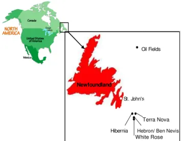
The East Coast of Canada, including offshore Newfoundland, has recently been considered to be a major new territory of petroleum production. As of May 2000, 125 exploration wells, 31 delineation wells and 27 development wells have been drilled offshore of the province on the Continental Shelf. Recoverable resources of 2.1 billion barrels of oil, 9.3 trillion cubic feet of natural gas and 413 million barrels of natural gas liquids have been discovered. All of the major oil discoveries have been in the Jeanne d'Arc Basin that covers about 14,000 square kilometres off the East Coast of Newfoundland [2]. Figure 1 shows the location of the first four offshore oil development offshore Newfoundland. Hibernia is in full production, Terra Nova is in the development phase, White Rose is scheduled for 2004, and Hebron/Ben Nevis is being investigated. At Hibernia the water depth is about 80 m, at Terra Nova 93 m, at White Rose 119 m and at Hebron/Ben Nevis about 95 m; the water depth increases to about 1100 m in the vicinity of the Flemish Cap.
The main discharge associated with offshore oil production is called "produced water". Produced water is a complex mixture of inorganic and organic compounds and has the potential to be toxic to the ocean environment [3]. Constituents of concern include metals, petroleum hydrocarbons, nutrients, radionuclides and treating chemicals. In one laboratory study, samples collected off the East Coast of Canada showed elevated levels of about 10 heavy metals, as well as hydrocarbons. In the same
study Microtox® assay results indicated an increase in produced water toxicity with time [4].
Typical discharge rates for produced water can be high. Over the life of the producing field, the quantity of discharge can be typically 10 times as high as the volume of hydrocarbon produced [5]. Models of the produced water discharge tend to predict that produced water will be rapidly diluted and dispersed when discharged into the ocean, however, little real data exist with which to corroborate these assertions [3].
St. John's
Hibernia
Oil Fields
Newfoundland
Figure 1. Offshore Newfoundland - the first four oil and gas development locations (after Terra Nova Alliance website). 2.1 THE ROLE OF THE REGULATORY AGENCIES IN OFFSHORE OIL AND GAS EXPLOITATION
The regulating bodies for offshore oil and gas production, such as the Canada-Newfoundland Offshore Petroleum Board (C-NOPB), have a strong mandate to ensure that offshore oil and gas activities proceed in an environmentally acceptable manner [6]. Due to the facts (a) that discharges are continuing at existing sites, (b) that the industry continues to find and develop new sites, and, (c) that an environmental mandate is in place, the programs and policies for environmental effects monitoring (EEM) need continual development. New and innovative means of acquiring information need to be considered.
In a press release on 21 January 2000, the C-NOPB made the following comments concerning environmental monitoring [6].
"Production operators must also develop and submit for C-NOPB approval environmental effects monitoring programs for their projects. Both Hibernia and Terra Nova programs were designed in consideration of international experience and site-specific discharge modelling. Hibernia’s program includes seabed sampling at 44 points around the platform as well as a scientific fishery in the vicinity of the facility.
Sediments have been found to be generally non-toxic, and elevated chemical concentrations were limited to 500 metres or less from the platform. No elevated contaminants have been detected in fish, nor were fish samples tainted. The C-NOPB also monitors and investigates incidents of spills of other fluids from offshore operations to determine the causes of such incidents and their potential effect on the environment. Since the start of Grand Banks oil production in 1997, a total of 92 incidents have been reported and investigated, and most of these have involved very small quantities of fluid (less than 10 litres). While some incidents are still under active investigation, none of the completed investigations indicated any evidence of operator neglect or disregard for safety and environmental regulations.
All information gathered by the C-NOPB is available to federal and provincial governments, and the board works closely with all relevant government departments and agencies, and with industry, to ensure that safety of workers and the protection of the environment are paramount principles in the development of offshore oil and gas resources."
2.2 NUMERICAL MODELLING FOR THE DISCHARGE OF PRODUCED WATER
A part of the OERE-AUV project concerns the development and validation of numerical models for (i) the hydrodynamic dispersion of discharges of produced waters into, and, (ii) the fate of drilling wastes (cuttings and muds) in, a marine environment.
In his thesis [5], Mukhtasor considered the engineering design of a discharge outfall for produced water from an offshore platform using hydrodynamic modelling and considerations of ecological risk assessment (ERA). His analysis includes the following items: developing and integrating an initial dilution model with a far-field dilution model for produced water discharge; developing a probabilistic methodology for hydrodynamic modelling; identifying methodologies for ERA of produced water discharge; and developing a framework for ecological risk-based design of a produced water outfall. The results are used to estimate the average concentrations of the various effluents.
2.3 NUMERICAL MODELLING FOR THE FATE OF DRILLING FLUIDS
In [7] Sadiq et al. describe the fate of drilling fluids that are discharged from offshore platforms. During oil well drilling operations, drilling fluid (or mud) is used for lubricating the drill bit, flushing rock cuttings out of the well, and maintaining borehole pressure. In response to effluent limitations in various parts of the world, including the North Sea, Gulf of Mexico and the east coast of Canada,
Hebron/ Ben Nevis White Rose
alternatives to water and oil-based muds have been developed and used over the last decade. These synthetic-based drilling fluids (SBF) are more efficient than water-based drilling fluids (WBF) for deep and complex formations and are environmentally less toxic than conventional mineral-oil-based drilling fluids (OBF). SBFs provide a significant pollution prevention opportunity because of better recycling qualities and smaller quantities of discharged metals in comparison to WBFs. As compared to OBFs, the drilling costs are lower, provided the cuttings associated with SBFs are discharged offshore. Since 1999 the US Environmental Protection Agency (US EPA) has been developing new regulations for the offshore disposal of SBFs, with the help of industry and other agencies. SBFs are non-dispersible in nature: they sink to the seafloor and therefore are a potential environmental concern to the benthic community. It is also believed that some environmental impacts are due to smothering by the drill cuttings, changes in grain size and composition, and anoxia caused by the decomposition of organic matter.
Previous hydrodynamic models were developed for the transport of chemical contaminants originating from offshore drilling residues that are deposited on the seabed, however these models were limited to the transport of the soluble constituents from the cuttings and mud deposits. Such models do not take into account particulate transport and chemical and biochemical transformations that degrade the contaminants that are within the sediment zone or boundary layer. The SBFs sink to the seabed due to their hydrophobic nature and the benthic communities may suffer effects due to increased levels of ester concentration in the pore water. The new model in [7] is useful as a screening tool for determining the fate of contaminants before conducting seabed surveys. For applications off the East Coast of Canada, a typical set of fate computations will be performed for a zone within 100 m from the point of discharge of the drilling waste into a water column of depth 50 m and a width of 1000 m.
2.4 REQUIREMENTS FOR OCEAN SAMPLING AND ENVIRONMENTAL MONITORING
Conventional strategies for ocean sampling involve the collection of samples of water and biological specimens using equipment that is usually deployed over the side of a ship, and the return of these samples to land laboratories for analysis. Such methods are tedious and sometimes inaccurate, as volatile chemicals will disappear quickly. One researcher has stated that produced water samples flown immediately to a laboratory by helicopter had much higher chemical concentrations than those returned by ship. Thus in-situ chemical analysis of samples is a desirable in order to keep the quality of the samples high. This could be achieved by equipping an underwater vehicle with suitable sampling and chemical analysis equipment.
An AUV is a self-propelled submersible robot capable of carrying out pre-programmed tasks without human intervention. An AUV can be hundreds of kilometres from any support vessel or shoreline, and completely out of contact with any external input for hours or days at a time while it completes its mission. AUVs are particularly suited for applications in hazardous environments because they do not require a human support team nearby or a tether to the surface. Therefore, they can, for example, find and classify undersea mines or examine the underneath of ice sheets without risking human injury or death.
AUVs are emerging as a commercially viable technology as ocean exploration heads into deeper waters. Without the encumbrance of the tether found on ROVs, or the need for a support ship, these vehicles provide a platform for a wide variety of offshore tasks, including:
• Oceanographic sampling and research • Environmental monitoring
• Iceberg profiling and tracking and under-ice mapping • Pipeline surveys
• Offshore oil and gas systems maintenance and support • Telecommunications cable surveys
• Hydrographic surveys
• Mine detection and countermeasures
From the above examples we see the necessity of having an AUV that is equipped with suitable sensors for detecting the presence of the chemicals in drilling wastes and produced waters and for validation of numerical models that predict the consequences of these discharges.
AUVs can be used for other aspects of environmental monitoring as was discussed at a recent workshop [8]. Here a group of biologists, chemists, geologists, physical oceanographers, geophysicists and AUV technology people discussed the role of AUV and sensor technology in the Census of Marine Life (CoML) and Chemosynthetic Ecosystems (ChEss) program. Here the application is to locate new hydrothermal vent (or seep) sites on the seabed, and to survey the life-forms found there; the long-range plan is to obtain a complete census of the marine life that inhabits the world’s vents and seeps.
For the AUV community that challenge translated into the following question: Is there a way(s) to use AUVs to assist the biologists, chemists, geologists, physical oceanographers, geophysicists et al. to get more and better data more cheaply and more quickly than is available now? While biogeography (diversity of species) is the main goal of the CoML project, any characterization of a hydrothermal vent (or seep) site includes biological, zoological, chemical, geological, oceanographic and other considerations and observations. So it was necessary to determine what the biologists (et al.) wanted to survey,
measure and sample and then how existing AUV and sensor technology could be used to accomplish this.
Since traditional marine biology research is performed via "ship cruises", the participants have extensive experience lowering nets and bottles over the side and even taking sediment cores, but few of them have experience with ROVs or manned submersibles and none had experience with AUVs. So it was somewhat of a challenge to convince the participants that an AUV could fulfill some of their data needs more efficiently than with traditional techniques. Typically marine scientists want to determine what chemicals are present (concentrations, production rates, dispersion rates), water (and plume constituent) temperatures, and, size and concentration of particulate matter. To this end they aim to obtain pictures (film or video) as well as samples (water, solids) in preference to the results of in-situ measurements by various sensors. As with any set of measurements it is necessary to determine what temporal and spatial scales are involved. At what scales do things need to be sampled or measured? What would be the optimal vertical (and horizontal) spacing between measurements? How frequently should one return to make these measurements to obtain statistically-reliable results?
Thus an AUV needs to be designed with the ability to (a) hover in place for long periods in cross-currents, and, (b) return to a known (x,y,z) position tomorrow, next week, next year etc.
Given the measurement requirements, what sensors already exist that can make these measurements? Are these sensors commercially available, are they in development or do they need to be invented? Are these sensors packaged sufficiently compactly to be usable in an AUV? What is the power consumption and duty cycle for these sensors? Are there measurements that could be made more effectively using multiple AUVs rather than with a single AUV? Is it necessary for all the AUVs in a fleet to be equipped with the same suite of sensors or can the instrumentation be more optimally deployed by having only a small number of different sensors in each AUV? Clearly a top priority is to have reliable instruments that require a minimum number of personnel for operational support.
What are the priority items for searching? Is the equipment required to detect the presence of any plumes (or seeps) within a designated area or is the priority to localize a particular plume? Is it necessary to detect and examine any "critters" and their behaviour?
Given certain priorities, what is the best search strategy? Do you program an AUV to inspect the first anomaly or do you program it first to complete the large-area survey then return to a few places for close-up investigation? The
answer depends on the goal of the project. Is the goal to enumerate all vent (seep) sites in a designated area or is the goal to examine one or more sites in detail? Is it better to study four sites in the same segment or to examine four sites in four different segments? Is the goal to search for and find the extremes of the population or is the goal to locate 95% of the population?
The answers to these questions are what determine the design requirements for an AUV that will be suitable for the intended application. As will be seen in this paper, there are some common requirements that stem from applications as seemingly diverse as for environmental monitoring of marine life during a census program and for the monitoring of the environmental effects of discharges from offshore oil and gas facilities.
Another possible application of an AUV in environmental monitoring (ice reconnaissance) is to proceed ahead of an icebreaking ship (particularly at night or during inclement weather when the on-board helicopter cannot fly) to determine where lies the path of weakest ice thereby informing the ship's captain what might be an optimal ice-breaking track.
AUV technology is becoming an increasingly useful concept that has now moved from a state of research and development to the beginnings of commercial acceptance [9,10,11]. The use of AUV technology as it applies to environmental monitoring is the main focus of this project. The main objective of this work is to design a payload for an AUV that will be capable of gaining valuable environmental data for the purposes of monitoring produced water discharges from offshore oil and gas installations, and, for detecting the presence of hydrocarbons etc. in the discharge of rock cuttings that although "washed" contain a residue of the drilling mud. 3.0 DEVELOPMENT OF AN AUV FOR EEM
In September of 1998, a collaborative effort between NRC-IMD and MUN-OERC began to design a streamlined AUV to serve as a testbed for IMD and graduate level research. The AUV, named the Canadian Self-Contained Off-the-shelf Underwater Testbed ("C-SCOUT"), is torpedo-shaped, with a diameter of 0.4 metres, and designed to have a high degree of function and manoeuvrability. With these general characteristics, the "C-SCOUT" has a high degree of versatility and ease of operation. The "C-SCOUT" AUV was designed to serve as a testbed for graduate level research initially focusing on control systems, propulsion systems, and vehicle endurance.
The "C-SCOUT" project became part of a larger Natural Sciences and Engineering Research Council (NSERC) Strategic Grant entitled "Offshore Environmental Risk Engineering using Autonomous Underwater Vehicles" (OERE-AUV) which involves a number of research and
industrial partners including the MUN-OERC, the NRC-IMD, C-CORE, the University of Victoria, Petro-Canada, ISE Ltd., and Geo-Resources Inc. The first planned mission for "C-SCOUT" is environmental effects monitoring and assessment of offshore petroleum discharges.
"C-SCOUT" was designed with high functionality and low cost in mind, and therefore is constructed of modular sections and outfitted with off-the-shelf components. The AUV is also designed for ease of operation, therefore it is sized to be launched from a small boat, and the batteries can be replaced while the vehicle is floating on the surface, with no special tools or equipment.
The proposed placement of the through-body thrusters provides control in heave, pitch, sway, yaw and roll; this makes the vehicle highly manoeuvrable even at low forward speeds, and thus able to hover in a cross-current. Although common practice is to use passive roll-stabilization (by deliberately separating the centres of gravity and buoyancy), the fully-actuated version will permit any orientation during hovering or even while inverted, which will permit a single sonar to point downwards (for bottom mapping), sideways (for iceberg profiling) and upwards (for under-ice profiling); see [12] for further details.
C-SCOUT can swim into a large pipe yet can travel backwards efficiently (so it does not need to turn about in order to exit the pipe). One of the features of "C-SCOUT" is that the fins can be rotated through 360 degrees so they will be rotated by 180 degrees (from their position when traveling straight ahead) in order to increase the manoeuvrability when traveling straight backwards.
3.1 CONCEPTUAL DESIGN FOR THE "C-SCOUT" AUV
The focus of the design concept was to create a general-purpose autonomous underwater vehicle that can be easily reconfigured. The vehicle is required to be able to cruise with a high degree of manoeuvrability and to be able to hover, even in a cross-current. The vehicle was therefore designed to be streamlined in shape, with an ellipsoid nose, parallel cylindrical midbody, and a cubic-spline tail.
To meet the requirements of a variety of environmental monitoring missions, "C-SCOUT" was designed to be highly manoeuvrable. It has multiple fins (control surfaces) and multiple through-body thrusters. The fins are used for manoeuvring at speeds above approximately three knots while the number and placement of the thrusters provides a high degree of control for positioning and orienting the vehicle while manoeuvring at low speeds or while hovering in-place within a cross-current. The manoeuvring capabilities make it possible to place and hold "C-SCOUT"-mounted equipment such as sensors or samplers
at known locations in the water column.
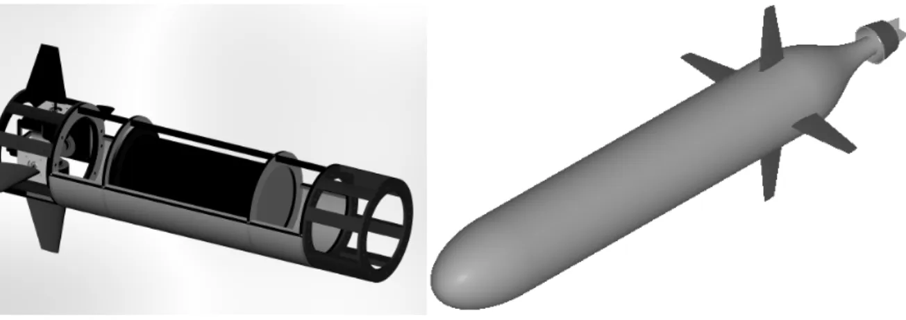
To make the vehicle easily adaptable to a wide variety of configurations, the AUV has been designed and constructed as simply as possible using modular sections; see Figure 2. These sections allow lengthening and shortening of the vehicle to accommodate various payloads and control actuator configurations. The length of the parallel midbody can be adjusted based on the mission requirements to give the vehicle a maximum length of four metres. Since the vehicle is free-flooding, except for a pressure vessel in the central module, adding modules does not require any sealing arrangements; it is just a matter of mechanical fastening with bolts.
To facilitate vehicle reconfiguration, nearly all of the onboard components are stock commercial items. Using such off-the-shelf items greatly reduces any downtime due to their failure since replacements are readily available. This allows new technologies to be tested using a vehicle constructed of proven components, thereby minimizing the effect of custom designed vehicle components.
3.2 RANGE OF "C-SCOUT" HULL CONFIGURATIONS The construction and testing of the vehicle is being accomplished in stages. The baseline configuration of the vehicle has four control surfaces aft, and a single thruster aft for propulsion; see Figure 2. The length of this configuration is 2.3 metres with a hull diameter of 0.4 metres and an overall width and height of 1.06 metres from fin-tip to fin-tip.
The fully-actuated configuration, still to be completed, has four aft control surfaces, plus four control surfaces forward of the centre of gravity; see Figure 3. In addition, the fully actuated version will be equipped with six through-body thrusters. Two thrusters are to be placed vertically - one forward (A) and one aft (B), and the remaining four are to be placed horizontally - two forward (C,D) and two aft (E,F). The placements of the thrusters gives control in pitch, heave, yaw, roll, and sway, with surge control accomplished by the main propulsor, making the vehicle highly manoeuvreable even at low speeds and able to hover in a crosscurrent. The common practice is to use passive roll stabilization via gravity-buoyancy effects, but the fully-actuated configuration "C-SCOUT" is designed to use thrusters so that it can maintain any orientation with ease, including hovering in place or inverted, which may be necessary for underwater observations or water sampling. The baseline configuration, however, exercises passive roll stabilization.
The overall dimensions of the vehicle were based on the components required onboard. These include an obstacle avoidance sonar, a computer system, a navigation and orientation system, an energy-storage system, and a payload
Figure 2. Baseline Configuration "C-SCOUT" AUV. Left image shows modular design and framework.
Figure 3. The fully-actuated "C-SCOUT" AUV such as cameras or oceanographic sensors. Thus the overall
length of the fully-actuated configuration will be about 3.3 m.
3.3 THE "C-SCOUT" IN-WATER TRIALS
Before an AUV is launched into the sea, it must undergo rigorous trials in a test pool or a shallow lake until its control system can be fully trusted in autonomous operation. A main factor in designing a control system is the use of the vehicle performance characteristics with respect to various hydrodynamic parameters which will change depending upon the AUV geometric configuration. These performance characteristics can be determined through rigorous tank testing.
3.4 "C-SCOUT" TEST SETUP
The final, fully operational "C-SCOUT" AUV will operate in a three-dimensional realm beneath the ocean surface. To navigate efficiently and effectively, the control system must be able to determine the vehicle's position and orientation accurately through the use of onboard sensors such as
Doppler velocity logs, accelerometers, gyroscopes, pressure sensors, altimeters, and tilt/roll sensors. The "C-SCOUT" AUV is still in its infancy, so the entire suite of sensors is not fully implemented and integrated. Therefore, to accurately determine the vehicle's position and orientation, an external system is required.
Due to the availability, accuracy required, and ease of use, the Peak Performance MOTUS optical tracking system was chosen. This system uses a standard mounted video camera to record the path of the vehicle during manoeuvres. This video is then digitized and the MOTUS software tracks user-selected points which are scaled and calibrated accordingly. These tracked points can then be plotted and analyzed for positions, velocities, and accelerations. This system can be used anywhere with a fixed video camera, so for testing "C-SCOUT", a camera will be located overhead in the IMD Ocean Engineering Basin (72 x 35 x 3.5 metres).
For the preliminary testing, a 1.2 metre long foil-shaped surface-piercing mast was attached to the framework of the
A
B
C
D
E
F
Figure 4. The "C-SCOUT" AUV complete with mast, wireless Ethernet adapter, and high-contrast markers. "C-SCOUT" AUV at the yaw centre predicted from
numerical simulations to mount a wireless Ethernet adapter to transfer control and feedback data to the onshore laptop system to track. Markers on the hull of the vehicle were not used due to parallax errors.
This system limits the vehicle to manoeuvres in a horizontal plane near the surface of the water and is not fully representative of the final vehicle configuration due to the addition of the mast. However, the precision with which the system can measure the vehicle track and the ease with which it can be set up and used make for a worthwhile tradeoff.
3.5 "C-SCOUT" FREE-SWIMMING TEST MANOEUVRES
The initial testing phase of the "C-SCOUT" AUV, which will take place in the IMD Ocean Engineering Basin, will focus on making a preliminary characterization of the vehicles manoeuvring performance. The planned test scheme is very similar to that of a surface ship - especially since the current communication system restricts the AUV to a two-dimensional realm near the surface.
The preliminary tests will include a series of turning circles through a range of speeds with a constant control surface deflection, a series of turning circles with a range of control surface deflection angles run at a constant speed, zigzags, figure-of-eight manoeuvres, starting/stopping/reversing performance, speed/power tests, and overall power consumption tests.
3.6 NUMERICAL SIMULATIONS FOR "C-SCOUT" MANOEUVRES
Concurrent with the design and construction of the "C-SCOUT" AUV, a numerical hydrodynamic simulation has been developed to aid in the control system design, mission planning, and post-launch mission analysis. The simulation was written in MATLAB and SIMULINK, and is a fully nonlinear model, based on Newton-Euler equations of motion in six degrees of freedom. The vehicle is assumed to be perfectly rigid, i.e., with no elastic deformations, and the mass of the vehicle is constant in magnitude and distribution. The force causing motion of the rigid body is the sum of gravitational, buoyancy, viscous, and pressure forces on the vehicle. The static forces of gravity and buoyancy are determined analytically. The pressure forces (added mass) are determined numerically, while the viscous damping forces are derived via lift and drag equations using empirical coefficients.
Once the mass and inertia properties of the physical vehicle are identified, they can be entered into the simulation and motions can be predicted. Once validated, the simulator can be used to run virtual vehicle missions in advance of the AUV being launched using the working control system to discover any bugs or glitches that may occur. During the mission, the simulator can be run in real time to virtually track the vehicle which would aid in recovery should anything go wrong.
Figure 5. Turning circles of the "C-SCOUT" AUV at 4 m/s from a numerical simulation.
Figure 6. Horizontal plane trajectory of the "C-SCOUT" AUV at 3 m/s with 20° of rudder, from a numerical simulation. Results from a series of numerical simulations of turning
circles for the "C-SCOUT" AUV running at 4 m/s are shown in Figure 5. One representative set of graphs of rudder angle command and vehicle yaw rate versus time are also shown in Figure 5. Figure 6 shows a sample figure-of-eight manoeuvre for the "C-SCOUT" vehicle at 3 m/s with the rudder angle command and vehicle yaw rate plotted. The mass and inertia properties of the vehicle are best-estimates using a spreadsheet tabulation; the actual properties of the physical vehicle have not yet been determined but they will be measured with a swinging
frame, a bifilar pendulum and via inclining tests. Numerical simulation results like these will be compared with the actual vehicle test results upon completion. 3.7 "C-SCOUT" FORCED-MOTION MODEL TESTS A full-sized, exact duplicate of the "C-SCOUT" AUV has also been constructed which will be tested for hydrodynamic coefficients using a large-amplitude Planar Motion Mechanism (PMM) in the IMD Ice Tank (91 x 12 x 3 m). The PMM experiments will be a third form of
Time (s)
Time (s)
validation for the simulation software, since the experiments will provide the bare hull hydrodynamic derivatives such as Y
v
, Nv
, Yr
, Nr
, Yv
D
, Nv
D
, Yr
D
and N
r
D
. Variations in vehicle geometry can be studiedsuch as control surface sizing and placement, or changing overall vehicle length by adding or removing modules. 4.0 THE EEM PAYLOAD AND IMPLICATIONS FOR VEHICLE DESIGN AND PERFORMANCE
The main challenges associated with designing environmental AUV payloads are concerned primarily with physical constraints, as described in section 4.1. Some sensors are designed in such a way that the voltage (or current) that travels through the sensor tip is proportional to some physical quantity in seawater e.g. temperature, pressure and conductivity. Since the output signal from such an instrument is continually changing, this output can be digitized at a high rate (hundreds or thousands of samples per second) limited only by the speed of the analogue-to-digital converter.
Such is the case with a typical turbulence probe that is used on an AUV to measure the characteristics of turbulence in the ocean; see [13]. The output signal requires no significant processing time ("analysis time") so the results (data) are available in "real time". The results can be recorded directly onto a hard disk or into solid-state memory. Thus a continuous stream of data samples is available that can be time-stamped with the position of the vehicle, at each instant.
Unlike this type of sensor, instruments that require the collection of water require a relatively long time to collect one "sample", and to provide the "results of analysis" from one water sample. For example a mass spectrometer requires that (i) a finite volume of seawater be collected and passed through the "sensing element", and that (ii) a finite amount of time (tens of seconds) be made available for the instrument to perform the requisite chemical analysis.
Seawater collection systems can cause great difficulty since (a) large sample volumes and duplicate samples are often required for monitoring, and, (b) the space in an AUV is often limited. Another concern associated with sampling is the sample storage requirement. As an example, offshore sampling often requires monitoring hydrocarbons, which must be stored in glass containers. Glass is fragile, heavy and cumbersome, making it difficult for use in an AUV. As sampling systems have the potential to be complicated in an AUV, sensors that can perform in-situ chemical analysis are the preferred method for gaining environmental data from water samples; on the other hand, an AUV with a robotic pick-up arm may be required for the collection of biological samples.
At the OCEANS 2000 conference and exhibit, one of the authors became acquainted with an innovative underwater mass spectrometer. It was decided to investigate this piece of equipment and determine its applicability for in-vehicle chemical analysis of produced waters. This idea was developed into a project that is detailed in the remainder of this paper. A description of the equipment used, the testing process, and future work is presented.
4.1 SAMPLING STRATEGIES AND IMPLICATIONS FOR VEHICLE DESIGN
There are two main strategies for taking water samples with AUVs. One is to use the AUV to collect samples for on-shore analysis later; the second is to use equipment within the AUV to perform an immediate on-site analysis. The collection of water samples introduces several challenges. One is that each of the samples must be collected into a separate container within the AUV and each container must be uniquely identified with at least a time and date and perhaps an (x,y,z) position within the ocean, as determined by the on-board inertial navigation, GPS or acoustic positioning system. These containers take up space within the vehicle, and, as the empty containers are filled with water there must be an on-board ballast compensation system so that the vehicle can maintain neutral buoyancy. Furthermore the containers and the ballast system must be located in the same part of the vehicle so that the centre of gravity does not move drastically with respect to the centre of buoyancy otherwise the static stability of the vehicle will be affected. Often duplicate samples must be taken and stored so this doubles the space that must be allocated within the vehicle for samples. A pumping and distribution system (to fill the containers sequentially) is also required which takes up space and has an associated energy cost during operation. In addition, certain chemical analyses require either preservatives or special container materials to prevent degradation.
The alternative arrangement, an in-situ flow-through analysis system, also has several drawbacks. Analytical instruments such as mass spectrometers require periodic calibrations and therefore require a reference fluid to establish a baseline for analysis. As such either a reference solution must be carried on board the AUV or the mass spectrometer is recalibrated once the mission is complete. If the calibration is done after the mission is complete there is a risk that the baseline has drifted throughout the sampling interval thereby compromising the accuracy of the readings. If the calibrating is done on board the AUV a pump and switching system is required and there is an energy cost associated with the pumping and switching systems. In addition there needs to be a ballast compensation system that accounts for the mass of "reference solution" consumed during the voyage. One could try to reduce the amount of time devoted to
"re-calibration" by using the "reference solution" only during the turn-about at the end of a leg of the "lawnmower" path.
Flow-through systems often have a low volume flow rate; the present flow rate for the mass spectrometer used here is of the order of six mL/m which means that it takes of the order of one minute to take in and analyze one sample, whether it is a sample of ocean water or "calibration solution". This may require that the vehicle be able to hover in place in the presence of cross-currents in order to station the intake probe at the required position (in terms of latitude, longitude and depth). If the vehicle cannot hover in place then the distance travelled during sampling can be significant and effectively a spatial averaging is taking place. It is therefore difficult to state that a particular sample was taken at a specific location within a discharge "plume" particularly if the sampling protocol requires the AUV to return to the same location each day, week or month, depending on the frequency of sampling that is inherent in the monitoring scheme. If the vehicle is unable to hover in place but can collect and analyze (or store) a sample within a short period of time, then the AUV may be able to collect several samples within a single "pass" at constant speed through the plume. Thus a post-voyage record of the location at which each sample was taken, and how far the vehicle travelled during the collection (and analysis) of each sample needs to be plotted as a sort of "error bar" on position.
It was with this need to hover in place during water sample collection that led to the incorporation of through-body (tunnel) thrusters in "C-SCOUT". During the first portion of the hover period the four lateral thrusters are used to position the vehicle (or probe) in place. If there is a strong horizontal cross-current a large amount of electrical power may be consumed particularly if the vertical fins (control surfaces) are oriented perpendicular to the direction of the current. Once the vehicle is "in position" the four vertical fins can be aligned with the direction of the water current and the thrust required from the four lateral thrusters can be subsequently reduced. 5.0 POTENTIAL EEM SENSORS AND SEA-TRIALS WITH AN EXISTING AUV
While "C-SCOUT" is being developed, the project team continues work on payload development and sensor investigation for environmental monitoring. A series of sea trials involving the use of an existing AUV and innovative equipment to delineate a near-shore ocean outfall is planned.
International Submarine Engineering Limited (ISE) in British Columbia is a world leader in the design and integration of autonomous and remotely operated vehicles. For more information please see [14] (www.ise.bc.ca). ISE are providing the use of their
autonomous underwater vehicle, "ARCS", which was developed by ISE Research Ltd. as a platform for underwater vehicle research for the Department of National Defence and the Canadian Hydrographic Service in the mid-nineteen-eighties. Since 1987 the vehicle has been used for the development and demonstration of AUV technologies including mission controllers, navigation systems, ballast and trimming systems, and advanced power sources. Over 800 successful dives have been conducted [14].
Physically, "ARCS" has changed through the years to reflect is various uses. Its diameter is 69 cm, its current length is 6.4 m and its depth rating is 300 m. With a propulsion unit of 2.5 HP its maximum speed is 5.5 knots. With a single 10 kWh nickel cadmium battery unit the range is 36 km at a speed of 4 knots; with two such battery units the range increases to 72 km at 4 kt.
5.1 DESCRIPTION OF EQUIPMENT FOR THE SEA-TRIALS
Applied Microsystems Ltd. (AML), in Sidney, British Columbia, is supplying all the analytical equipment. AML designs, manufactures and sells scientific instrumentation for water quality monitoring. For more information, see [15] (www.appliedmicrosystems.com).
5.2 THE MASS SPECTROMETER
A mass spectrometer is an instrument used for identifying the chemical constitution of a substance by means of the separation of compounds according to their differing mass and charge. The AML mass spectrometer that will be used for this project has the product name "In-Spectr". It is an innovative underwater mass spectrometer. This mass spectrometer was developed at the Center for Ocean Technology at the University of South Florida which is an engineering organization aimed at developing innovative marine sensors and instrumentation. Due to a lack of adequate equipment in the commercial marketplace, the Center for Ocean Technology undertook the task of developing an in-situ mass spectrometer as a future payload for AUVs. They chose the mass spectrometer as the sensor of choice due to the breadth, versatility and power of the technology. Applied Microsystems Ltd secured a licensing agreement with the University of South Florida for the commercialization and distribution of the instrument. The development of the mass spectrometer at AML is an on-going process that continually changes to suit the needs of the consumer and the mission [15].
Although the mass spectrometer system has been previously described in [16], an overview is given here, which reflects the on-going changes to the system. The initial system was based on a quadruple mass filter coupled to a membrane introduction interface for
detection and quantification of volatile organic compounds (VOCs) and dissolved gases to 200 atomic mass units (amu) at parts-per-billion (ppb) levels. Membrane introduction is an efficient means of transporting volatile non-polar species from the water column into the vacuum system of the mass spectrometer. The main challenge to underwater mass spectrometry is the fact that mass spectrometry must be performed in a vacuum. Most vacuum pumps ultimately compress pumped gases and exhaust them into the atmosphere. This is problematic inside a closed pressure vessel system. If the pressure at the vacuum-pump exhaust port increases substantially above atmospheric pressure the pumps will cease to operate properly. This problem has been alleviated in the mass spectrometer by isolating the final stage of pumping inside a separate pressure vessel that can be evacuated to around one-quarter of one atmosphere pressure at the beginning of each operation which allows continuous underwater operation in excess of a week [15]. The underwater mass spectrometry system is housed in three separate pressure vessels that are connected in series for deployment. The front vessel serves as the sample collection system and contains a pump and a flow injection system. Sample water is continuously pumped into a 1-mL sample loop, the contents of which are periodically swept into the membrane introduction mass spectrometer (MIMS) system in the central vessel by switching the flow injection valve. Pumping deionized (DI) water from a reservoir bag into the MIMS interface probe displaces samples. In this manner changes in ion intensities for selected masses can be continually compared to background levels in the mass spectrometer. It is possible to use a carbon filter rather than deionized water that will reduce the complications associated with the reservoir bag and related plumbing. In addition, a continuous mode of sampling can be used. This type of sampling will eliminate the need to switch the flow injection valve which will reduce sample time. The continuous sample mode does not compare samples against a background level to give discreet values. Instead, it compare changes in concentration as the mass spectrometer is moved through the water stream. The central pressure vessel contains the main components of the mass spectrometer. These components include the vacuum chamber and mass analyzer with membrane introduction probe, associated electronics, turbo molecular vacuum pump and controller, CardPCTM motherboard with 72MB DiskOnChip memory, and a power distribution board which can be interfaced with an external computer that activates the various components in sequence. The third vessel contains two dry diaphragm pumps in series that serve as backing pumps for the turbo pump. The practical depth of deployment for this system is presently limited to 30 metres [15].
The entire system is powered by 24 VDC and consumes less than 95 Watts with all components in operation. The
mass of the entire system is 38.5 kg in air, yet it is nearly neutrally buoyant in water. The overall dimensions are 123 cm in length and 19 cm in diameter [17]. Figure 7 shows the "In-Spectr" installed in one of the Florida Atlantic University (FAU) AUVs.
Figure 7. The "In-Spectr" mass spectrometer installed in one of the Florida Atlantic University AUVs.
5.3 THE CTD MICRO SENSOR
The second piece of equipment on the payload measures conductivity, temperature and depth (CTD) of the seawater. AML supplies a variety of CTDs however, the AML CTD Micro Sensor has been chosen because of its low weight and small size.
The AML CTD Micro Sensor is a miniature, high accuracy, high resolution, low power probe with rapid response sensors and sampling rates to 25 Hz. Physically, it is about 50 mm in diameter and its length is 280 mm without the battery option and is 426 mm with the battery. It is able to produce real-time data, internal logging, external or internal power and programmable sampling rates [18]. For additional information, see [15].
6.0 SEA TRIAL PREPARATION 6.1 MOUNTING THE EQUIPMENT
The mass spectrometer will be mounted in the payload bay of the "ARCS" vehicle using specially designed mounting blocks. These blocks have been designed to fit the radii of both the "ARCS" vehicle and the mass spectrometer. A small layer of neoprene foam lines the inside of the block ensures a snug fit around the mass spectrometer and prevents damage to the casing of the equipment. The CTD Micro Sensor will be mounted vertically in the nose cone of ARCS.
6.2 MISSION PLAN
The "ARCS" vehicle will be programmed to perform the required mission using an ISE technical support team. The vehicle will be programmed to follow a route similar to that of Laval, 1997 [19], using a "lawnmower" pattern. A lawnmower pattern is the term used to describe the movement of the vehicle through a series of parallel lines which are connected by semi-circular turns. For [19], there were four lines of about one km in length each. This horizontal pattern will be repeated at several depths. 6.3 SELECTION OF THE TESTING AREA
The plume initially chosen for testing is that formed by the discharge of the cooling water effluent from the Burrard Thermal Generating Station (BTGS) near Vancouver, British Columbia. The BTGS is a natural gas fired steam generating station. Water is taken from the ocean for cooling purposes and is discharged about 2.5 m below mean low tide, and about 35 m from shore. While in the plant the water heats to a temperature about 10 degrees C above ambient. Chlorine gas is added to prevent bio-fouling of the pipes. To reduce the chlorine levels to an acceptable discharge concentration, less than 20 ppb as required by the BC Ministry of the Environment, a de-chlorination process using sulphur dioxide is used. Routinely the chlorine concentration at discharge is non-detectable at 10 ppb [20].
The CTD will be used mainly to detect the thermal plume. Initially it was proposed to use the mass spectrometer to compliment the CTD measurements, however, in order for the mass spectrometer to be used, a chemical must be present for detection. For this reason it was proposed to add a tracer to the plume.
A true tracer should have properties similar to that of the effluent. However, it must also be compatible with the mass spectrometer. The tracer must have the following properties in order for the mass spectrometer to be able to detect it at this stage in development: (a) it must be non-polar so that the membrane can separate it from the water stream and (b) it must have a molecular weight no more than 200 atomic mass units. In addition to these constraints, the tracer must be non-toxic so that it will not damage the environment in which it will be added. Several tracers were considered for this mission including rhodamine dye, sulphur hexafluoride and dimethyl sulphide (DMS). Of the options, only DMS was feasible. The mass spectrometer can not measure rhodamine dye as it does not meet the constraint for atomic mass. Sulphur hexafluoride is difficult to introduce to the water stream and is used mainly for tests performed over longer periods such as months or years.
This mass spectrometer can successfully detect DMS in concentrations as low as one to five parts per billion. However, due to the large flow rates of the Burrard effluent and the dilution factors involved, the volume of DMS that would have been required was not realistic. As a result it was determined that due to the constraints introduced by the effleunt stream a tracer study was not feasible. It should be noted that this is not a limitation of the mass spectrometer but rather of the BTGS plume in that it is too "clean". A produced water discharge from an offshore platform would contain contaminants such as hydrocarbons that could easily be detected by the mass spectrometer.
The aim of the project is now to run the tests in the vicinity of the BTGS with the aim of detecting non-point pollutants. The area selected receives surface run-off from a variety of sources including a highway, railway and two refineries (non-operating). Three water samples will be taken and sent to a laboratory to determine what specific pollutants may be in the area. This information will be used to determine what contaminants the mass spectrometer should be programmed to trace. The focus at this time is on hydrocarbon pollutants. This study will actually be a better test of the capabilities of the underwater mass spectrometer as it will be attempting to identify the contaminants associated with a variety of sources.
7.0 RESULTS
Testing of the mass spectrometer and CTD sensor is scheduled for mid-October 2001. Once data collection has been completed, the results will be analyzed to determine how well the mass spectrometer works, in conjunction, with an AUV, for the purposes of plume delineation. The CTD data will be studied as it compliments the data gained by the mass spectrometer.
All data will be mapped spatially by comparing the temporal information given for the vehicle, the mass spectrometer and the AUV. "ARCS" logs its navigational data with respect to time. Both the CTD Micro Sensor and the mass spectrometer log data with respect to time as well. The times for both instruments will be synchronized with the times on the vehicle, which will allow the navigational location to be paired with the scientific data. Once the data have been plotted spatially, the reliability and value of the data will be better understood.
8.0 SUMMARY AND CONCLUSIONS
As the offshore oil and gas industry continues to grow, it is important to monitor the effects of the associated discharges into the marine environment. To do this effectively, new and innovative means of EEM need to be investigated and considered, including the use of novel
instrumentation on-board an autonomous underwater vehicle (AUV).
This paper reviews the need for the development and validation of numerical models for (i) the hydrodynamic dispersion of discharges of produced waters into an offshore environment, and, (ii) the fate of drilling wastes (cuttings and muds) therein. The results can be used to estimate the average concentrations of the various effluents and lead to considerations of ecological risk assessment (ERA).
There are two main strategies for taking water samples with AUVs: one is to use the AUV to collect samples for on-shore analysis later; the second is to use equipment within the AUV to perform an immediate on-site analysis. The advantages and disadvantages of each strategy are discussed.
It is shown how the type of instruments, sensors and sampling equipment can have a major influence on the design of an AUV, in particular the following items: instrument flow-through time, vehicle hover time, requirements for (x,y,z) position-stamping of samples, spatial averaging of data during sampling, pumping and storage systems for samples and "reference solutions", frequency of instrument "recalibration", and, ballast-compensation systems.
This paper describes a project that will use an existing AUV with innovative sensors to investigate plume delineation. The main sensor to be investigated is an underwater mass spectrometer, in conjunction with a CTD sensor.
Thus the focus of the design concept for "C-SCOUT" is to create a general-purpose AUV that can be easily reconfigured. The vehicle is required to be able to cruise with a high degree of manoeuvrability and to be able to hover, even in a cross-current.
Sea trials will aid in determining the advantages and disadvantages associated with using AUVs for environmental monitoring (EEM). This information will be used when setting up future missions for the "C-SCOUT" AUV.
9.0 ACKNOWLEDGEMENTS
The authors wish to recognize the technical contributions of the many graduate students, work term students, and IMD and MUN personnel and faculty. The Natural Sciences and Engineering Research Council (NSERC) is also to be thanked for financial support in the form of a postgraduate scholarship awarded to Douglas Perrault and an NSERC Strategic Project "Offshore Environmental Engineering Using Autonomous Underwater Vehicles". The NRC-IMD provided fellowship support to Timothy
Curtis and Douglas Perrault, and also provided funds for partial manufacturing of "C-SCOUT". In addition, thanks are extended to Applied Microsystems Ltd. and International Submarine Engineering Ltd. for their kind contributions.
10.0 REFERENCES
[1] Bose, N., 1999, Application document for NSERC Strategic Project "Offshore environmental engineering using autonomous underwater vehicles".
See http://www.engr.mun.ca/~bveitch/
[2] Government of Newfoundland and Labrador, Department of Mines and Energy, Energy Branch, Sedimentary Basins and Hydrocarbon Potential of Newfoundland and Labrador, St. John's, 2000.
[3] Anderson, M.R., R.B. Rivkin, and P.Warren, "The Influence of Produced Water on Natural Populations of Marine Bacteria". Proceedings of the 27th Annual Aquatic Toxicity Workshop, October 1-4, 2000, St. John's, Newfoundland.
[4] Lee, K., G. Wohlgeschaffen, K. Azetsu-Scott, S. Niven, P. Yeats, and J. Dalziel, "Potential Toxicity of Produced Water from the Canadian Offshore Oil and Gas Industry". Proceedings of the 27th Annual Aquatic Toxicity Workshop, October 1-4, 2000, St. John's, Newfoundland.
[5] Mukhtasor, PhD thesis, "Hydrodynamic modeling and ecological risk-based design of produced water discharge from an offshore platform", Memorial University of Newfoundland, May 2000.
[6] Canada-Newfoundland Offshore Petroleum Board (C-NOPB). http://www.cnopb.nfnet.com/
Site Updated: June 14, 2001 Site Accessed: June 15, 2001
[7] Sadiq R., Husain T., Veitch B., and Bose N., "Fate of Drilling Wastes in the Marine Environment: Water-Sediment Interaction Modeling", to appear in: Petrotech 2001, Bahrain, October 29-31 2001.
[8] Williams, C.D. "Report from the Working Group on Autonomous Underwater Vehicle (AUV) and Sensor Technology", Workshop on the Census of Marine Life (CoML) and Chemosynthetic Ecosystems (ChEss), Clark Laboratory, Woods Hole Oceanographic Institution, March 16 & 17, 2001. National Research Council Canada, Institute for Marine Dynamics, report LM-2001-03, March 2001.
[9] Wernli, R.L., "AUV Commercialization - Who's Leading the Pack?". Proceedings of OCEANS 2000 MTS/IEEE Conference and Exhibition, Providence,
Rhode Island. September 11-14, 2000, vol. 1, pp391-395. [10] "Maridan 600 cuts the umbilical" and "Ready for take-off", Maridan A/S Newsletter, Issue No. 11, April 2001, http://www.maridan.dk.
[11] "Survey AUVs are Proven Technology", Maridan A/S publication, http://www.maridan.dk.
[12] Curtis, T.L., D.Perrault, C.D.Williams and N.Bose; "Maneuvering of the C-SCOUT AUV", Proceedings of the 26th American Towing Tank Conference (ATTC), Webb Institute, Glen Cove, NY, 23 & 24 July 2001. [13] Levine, E.R., L. Goodman and R. G. Lueck; "Sensing requirements to quantify turbulence from an AUV", Oceanology International Americas 2001, AUV Sensor Workshop, 4 April 2001, Miami, FL.
[14] International Submarine Engineering (ISE) Ltd. http://www.ise.bc.ca/
Site Updated: June 18, 2001 Site Accessed: July 2, 2001 [15] Applied Microsystems Ltd.
http://www.appliedmicrosystems.com Site Updated: May 2, 2001
Site Accessed: July 2, 2001
[16] Short, R.T., D. P. Fries, M.L. Kerr, and R. H. Byrne, "Chemical Analysis Using Mass Spectrometry on Unmanned Underwater Vehicles", Proceedings of OCEANS 2000 MTS/IEEE Conference and Exhibition, Providence, Rhode Island. September 11-14, 2000. Vol. 1, pp. 605-609.
[17] Mass spectrometer fact sheet available from [15] [18] CTD fact sheet available from [15]
[19] Simon Fraser University, Underwater Research Laboratory, 1997.
http://www.ensc.sfu.ca/research/url/ Site updated: August 26, 1998 Site Accessed: July 3, 2001
[20] Personal communications: Al Brotherston, Manager of Environmental Affairs, Burrard Thermal Generating Station, Port Moody, British Columbia. May to August 2001.