Airfoil Vortex Induced Vibration Suppression Devices
by
Evan J. Lee
B.S. Naval Architecture and Marine Engineering, Webb Institute, 2005 Submitted in partial fulfillment of the requirements for the degree of
Master of Science in Naval Architecture and Marine Engineering
and
Master of Science in Ocean Systems Management
at theMassachusetts Institute of Technology
May 2007 TIS author hereby grants to MIT penrm'"eon to raprodww and te distribute publicly paper and electronic copies of this thesis docume
in whole or in part in any medium now known or hereafter created.
Signature of Author: ... .. ...
, Department of Mechanical Engineering
May 17, 2007
Certified by: ...
L7
--' -4- ...
Michael Triantafyllou Director, Center for Ocean Engineering
/ ( Thesis Supervisor
Certified by: ...
Henry Marcus Professor of Marine Systems Thesis Supervisor
Accepted by: ...
Lallit Anand, Professor of Mechanical Engineering
Chairman, Graduate Committee
MASSACHUSETTS INSTITUTE
OF TECHNLOGY
Airfoil Vortex Induced Vibration Suppression Devices
ByEvan J. Lee
Submitted to the Department Of Engineering on May 17, 2007 in Partial Fulfillment of the Requirements for the Degree of Master of Science in
Naval Architecture and Marine Engineering and Master of Science in Ocean Systems Management
Abstract
Vortex Induced Vibrations (VIV) is a major concern of the offshore oil industry. This problem leads to fatigue failure in the marine risers and causes costly replacement of the risers. Appendages such as helical strakes have proven that VIV can be eliminated but at the cost of increased drag. Increased drag reduces the time that the riser can operate. This thesis looks at adding airfoils to cylinders to both eliminate VIV as well as reducing drag. Two sets of tests were performed at the MIT Towing Tank to determine the effectiveness of these airfoils. The first tests utilized a flexible to model a riser. The second set of tests used a rigid cylinder to better understand the dynamics of the system. The airfoils were able to achieve both goals when the airfoils are aligned with the flow. Future work needs to be completed to study the airfoils when they are not aligned with the flow.
Thesis Supervisor: Michael Triantafyllou
Title: Director, Center for Ocean Engineering and Professor of Mechanical and Ocean Engineering
Thesis Supervisor: Henry Marcus Title: Professor of Marine Systems
Contents
I
Introduction ... 41.1 Vortex Induced Vibrations ... 4
1.3 M arine Risers ... 6
1.4 Cost Benefits of Reducing Drag ... 8
1.5 Previous W ork ... 9
1.6 Scope ... 13
1.7 Tow Tank ... 14
1.8 Force Sensor ... 15
2 Experiments ... 16
2.1 Flexible Cylinder Test ... 16
2.1.1 Cylinder Construction ... 16
2.1.2 Flexible Cylinder Rig ... 17
2.1.3 Testing Evolution ... 18
2.1.4 Airfoils ... 19
2.1.5 Results ... 21
2.2 Large Airfoils ... 28
2.2.1 Spring Cylinder Rig ... 28
2.2.2 Linear M otor System ... 33
2.2.3 Sensors ... 34
2.2.4 Large Airfoils ... 35
2.2.5 Testing Procedure ... 38
2.2.6 Results ... 41
3 -Concluding Rem arks ... 48
3.1 Conclusions ... 48
3.2 Recomm endations for Future W ork ... 49
Bibliography ... 51 Appendix A ... 52 Flexible Cylinder ... 52 Arrangement A ... 52 Arrangement B ... 53 Arrangement C ... 54 Arrangement D and E ... 55 Rigid Cylinder ... 56 Arrangement A ... 56 Arrangement C ... 58
Arrangement A3 Fixed and D3 Fixed ... 60
Appendix B ... 61
Chapter 1
Introduction
1.1 Vortex Induced Vibrations
Vortex induced vibrations (VIV) is a phenomenon that is exhibited by many bluff bodies. A simple example of VIV is when pulling one's hand and arm through the water. It is very difficult to prevent one's arm from vibrating back and forth. To understand VIV one must first understand the flow around an object. When an object is placed in a flow, the fluid will bend around the object. As the flow bends around the object, it will no longer travel smoothly, but become turbulent. This is due to the boundary condition on the surface of the object. At the surface, the velocity of the fluid is the velocity of the surface.
If the object is shaped such that there is a positive pressure gradient moving in the
direction of the flow, separation can occur. Separation is the transition from smooth flow to chaotic flow or from laminar to turbulent flow (Figure 1.).
POSITIVE PRESSURE GRADIENT
Vortex
The turbulent zone between the separation on the top and bottom of the body is called the wake. The wake is of much lower pressure than the high pressure region on the front of the body. Thus there is a net force in the direction of flow called form drag. As Figure 2. shows, the flow around the object depends heavily on the shape of the object.
(A) PLOW PATTERN OF CIRCULAR CYLINDER IN NON'YISCOUS FLOW; NO DRAG.
(B) CYLINDER AT REYNOLDS NUMBERS IN THE ORDER OF 40; CD.,Af 1.2.
(C) CYLINDER BETWEEN R =104 and 105; VORTEX STREET WITH CD- 1.2.
(D) PLATE WITH "SPLITTER" DEVICE IN WAKE; CD. - 1.6.
(E) CYLINDER ABOVE CRITICAL REYNOLDS NUMBER WITH CD - 0.3.
(7) STREAMLINE SECTION WITH CD. IN THE ORDER OF 0.06.
Figure 2. Flow Around Bodies (Hoerner 1965)
The smaller the wake is behind an object, the lower the form drag the body has (Figure 2f.). On bluff bodies, such as cylinders (Figure 2c.), vortices are alternately shed in the
wake. A vortex is fluid rotating in a clockwise or counter clockwise direction. This
alternating vortex pattern is called the Von Kirmin Vortex Street. These vortices have low pressure causing a force towards the side that the vortex was shed. The vortex shedding is dependant on the Reynolds Number.
Re = (1)
Re=Reynolds Number
U=Velocity of fluid
D=Diameter of object v=Kinematic Viscosity
The tests were performed at Reynolds Numbers between 20,000 and 80,000. This places the tests within the range for vortex shedding. When the frequency of vortex shedding is the same as the natural frequency of the cylinder, the alternating force of each vortex being shed would cause the cylinder to VIV.
1.3 Marine Risers
Marine risers are a key component of extracting oil from the undersea ocean deposits. The riser connects the drilling site to the oil platform. It provides a passage way for the drill to reach the drilling site and also is the pipe that the oil is pumped out of. One would think that being made of steel, the risers would not be able to flex. At the great depths that the oil companies are drilling at these days, the marine riser is not rigid, but acts like a tensioned string. The natural frequency of a string is dictated by the following equation (Blevins 1977).
EI
fn = 4(2)
E=Modulus of elasticity I=Moment of inertia M=Mass per unit length
L=Length
As the length of the marine riser increases, the frequency goes down the most because it is raised to the fourth power. Increasing the mass also decreases the natural frequency. Increasing the modulus of elasticity and the moment of inertia increases the natural frequency. At the Reynolds Number that the marine risers operate at, the Strouhal Number is about 0.2 f,D S =fs (3) fn=Natural frequency D=Diameter of Cylinder U=Inflow Velocity
The marine riser has natural frequency that is near the shedding frequency of the cylinder. Thus bare marine risers VIV when currents flow over them. This vibration causes fatigue stress on the riser that leads to failure. Fatigue failure is best exhibited when one bends a paper clip back and forth and after many repetitions, it snaps. Another concern with the marine riser is the drag that imparted on the cylinder. Once again since the marine riser is very long and acts like a string, so as the drag is imparted on the cylinder, it bows in the middle. This bowing causes an angle at both the top and the bottom of the marine riser. The drill is limited to a certain range of angles in which it can operate. If the currents are too strong, the marine riser will bend excessively and the drill cannot be used. This lost drilling time costs the oil company. Over the Reynolds
Numbers that were tested, the drag coefficient is about 1.2. When the cylinder is vibrating, the wake becomes larger as the vortices are shed at the peak of the motion. Therefore the drag increases for vibrating cylinders. So oil companies are looking to
eliminate vibrations to eliminate fatigue failure and reduce drag to allow for more drilling time.
1.4
Cost
Benefits of Reducing Drag
The cost of oil production has been ever increasing. With the high prices of oil, drilling rigs have been ever increasing in prices. The largest offshore drilling rigs are being chartered at $400,000 a day (Sanders). Every day that the rig is not drilling is lost revenue and hurt profits. Therefore reducing the drag imparted on the marine riser to reduce the bowing and increase the days of production is imperative. The P-36
semisubmersible oil rig has a maximum production of about 180,000 barrels per day (Offshore-Technology). James Mulva of ConocoPhillips stated that of every gallon of oil sold, the oil companies earn about 10 cents of profits (PBS). A sensitivity analysis was performed to determine the number of extra days that the modified marine riser would have to operate to pay back the extra cost of the modifications to the marine riser. The number of barrels that is produced by the oil rig as well as the cost difference between the two risers was analyzed. The data can be seen in Appendix C. As seen in Figure 3., at lower production levels, the number of days to break even increases dramatically. This would mean that the cost benefit of the reducing the drag of the marine riser would not be great. On the other hand, as the number of barrels produced per day increases, the
incremental reduction of number of days to break even is reduced. Thus it is important to use a lower drag marine riser on large oil platforms, but the benefit pushing production higher is not that great. The differential cost per day also has a large impact on the number of days to break even. The number of days to break even is directly proportional
VIV. The cost of the bare marine riser would increase due to maintenance replacement from fatigue failure and possibly failure.
Days to Break Even vs. Barrels per day
70.00 -60.00 50.0000 ---- $,000 --- $10,000 0.00 0,000 1A 0.00-a -4~-$30,000 *--$40,000 a --- $50,000 30.00- ~,000$60 20.00--10.00 0.00 0 20,000 40,000 60,000 80,000 100,000 120,000 140,000 160,000 180,000 200,000
Barrels Per Day
Figure3. Days to Break Even
1.5 Previous Work
M.M. Zdravkovich, in his paper, Review and Classification of Various
Aerodynamic and Hydrodynamic Means for Suppressing Vortex Shedding, compiled VIV suppression devices that were tested at the time (Figure 4.). There are four major groups of suppression devices. The first is omni-directional devices, Group i(a). The flow direction does not change the effectiveness of an omni-directional device. The second group, Group i(a), are uni-directional devices. These devices have an optimal direction in
which they are most effective. Group ii, are shrouds, which completely go over the cylinder. Group iii are miscellaneous suppression devices.
1(o) IN U Ge -
I
@1
e
7(21) 8(26) 13(21) 14(28) 19(32) 20(33) e 3(18)e
9 (27) 15 ( 29) 21 (34)Figure 4. VIV Suppression Devices
Each arrangement is shown in both the cross-sectional view and the longitudinal view. The plus sign next to the arrangement indicates that it was successful in eliminating
vibrations and drag coefficient is noted if known. The helical strake (Figure 4(1).) is a design that is successful in eliminating VIV but at the expense of increased drag. A
E) 4(25) 10(22)
el]
16 (29) 22(34)TN
5(19) -r 11(23) 17(34)C
23 (35)e
6(20) O aTI 0,0
12 (24) 18 (31) 24(36)rectangular or pyramid shape protrusion is added to the surface of the cylinder and
wrapped along the length of the cylinder like a helix. A cylinder usually has three or four of these protrusions per cylinder. Research has shown that this arrangement is able to disrupt the Von Kirmdn Vortex Street. The increased cross-sectional area of the helical
strake arrangement increases the drag on the cylinder. A benefit of helical strakes is that it is omni-directional. No matter which direction the flow is coming into the cylinder, the helical strakes eliminate VIV. The purpose of the research is to eliminate VIV while also decreasing drag. One possible solution to this problem that has been tested before, but not studied extensively is the use of airfoils (Figure 4(21 and 22)). If airfoils are placed on either side of a cylinder, they can redirect the flow. By redirecting the flow, the goal is to disrupt the Von Kdrmin Vortex Street and eliminate VIV. Also by redirecting the flow, the width of the wake can be reduced and as a result have a lower drag.
G. Grimminger in his paper Effect of Rigid Guide Vanes on the Vibration and Drag of a Towed Circular Cylinder first looked at applying guide vanes to redirect the flow around a cylinder. 15/16" brass cylinders were cantilevered from the ship model carriage and towed at David Taylor Model Basin. A brass plate was placed 3" below the water surface to eliminate surface effects. A dynamometer was used to measure the drag of the cylinder. The guide vanes were made of 1/64" (1/60D) thick pieces of copper and offset by a 1/10" (8/75D) washer. Figure 5. shows the arrangements of the guide vanes. Guide Vane 1 had the longest overall length at 2" and also extended 0.2" forward of the vertical point. Guide Vane 2 is shorter in length and only extends 0.125" forward of the vertical point. Guide Vane 3 has the same length aft of the vertical point but arcs around to 450 forward of the vertical point. Guide Vane 4 only utilizes flat pieces of copper. For
Guide Vanes 1, 2, and 3, the gap at the trailing edge of the two Guide Vanes was varied. The results showed that none of the arrangements exhibited vibration. Figure 6. shows that as the gap between the foils was increased, the drag was reduced. The width could be increased to about the size of the cylinder and still be effective. Guide Vane 3 was the most effective of the arrangements that were tested.
Guide Vanes Direction of Motion u .80- 0. 1 25" 0.2 Guide Vanes2 00.80 41* 0. 57" R 0. 2"1 1.43 Guide Vanes 3 hO.80"
hot.2
5"
0 Gud V0.937" D -0.921 Guide Vanes 460 0.5 0 A-No Vibration 0.75" 6 No- Vibration Resonance 0 -s'-~-- 4* --- # *
K
/
-____ 4 090 W4 i-S2V,
3 4 5 6 ___ / -4-/ / - -_v r
-_plain 0 Resonance Vibration * nof Large Amplitude
Cylinder of 4.25 knots Some Vibration No Vibration
'4
K
e
I/
7 8 9 10 Speed in knotsFigure 6. Guide Vane 1 with variation in gap opening
1.6 Scope
'it
50 45 40 35 C CL 0. 0 IA 25 20 5 0I
15160
/ d
The scope of research covers two different experiments with airfoils. The first
experiment exclusively looked at the foils fixed to the flow. The airfoils were mounted on a flexible cylinder that closely modeled a marine riser. The second experiment studied both fixed and freely rotating foils. These airfoils were mounted on a rigid cylinder that was allowed to move transverse to the flow.
1.7 Tow Tank
The MIT Towing Tank is 100ft long, 8ft wide, and 4ft deep. The carriage is supported by an overhead rail and a rail on the side of the tank. The carriage carries the testing equipment and provides a point where the test specimens can be mounted. The carriage is pulled by metal belt that is powered by servo motor. The MIT Towing Tank last year was upgraded last year and a new motion controller and motor with installed. The data acquisition now could operate both the carriage and record data. At the beginning of testing, three different computers had to be used. The first was the data acquisition computer. Second was the computer to run the motion controller. The third was to reset the Kistler force sensors. This created a lot of work for each run and the system was streamlined. Using a system that was developed for remote operation of the MIT Towing Tank, operating the carriage, recording data, and resetting the force sensors were all combined into one program. The additional benefit of this program is that the complete set of tests for an arrangement could be queued up and the carriage would reset the force sensors, start the carriage, record the data, back the carriage to its original position, wait for the tank to calm down, and repeat the test.
1.8 Force Sensor
The force sensor used was common to both sets of tests. The sensor is a Kistler piezoelectric three-axis sensor. The sensors look like small rings with a hole in the middle. These sensors work under compression and measure the shear forces imparted on the sensor. The sensors are placed on a bolt and clamped tight to create the
compression that is needed. The sensors are mounted on the bottom on each spar and the cylinder is mounted onto the bolt on each end. These sensors output charge and are converted by amplifiers on the carriage to an output voltage that could be read by the data acquisition system. The sensors have drift and will create an error over time. Therefore the amplifiers need to be reset to zero before each run. This can be done remotely or at the amplifier itself.
Chapter 2
Experiments
2.1 Flexible Cylinder Test
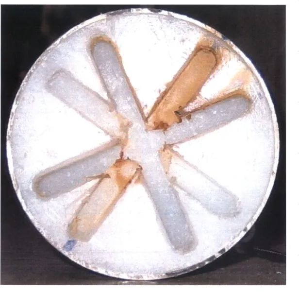
2.1.1 Cylinder Construction
The first set of tests that were performed on airfoils at the MIT Towing Tank was the flexible cylinder experiment. To better simulate a marine riser, a flexible rather than a rigid cylinder was used. This test allowed for three dimensional motions. The cylinder was made from a flexible rubber and was supported by Kevlar strings in the middle of the cylinder. The Kevlar allowed the cylinder to be tensioned and provided the restoring force to generate the desired natural frequency. A mold was made by slicing a 1.5 inch PVC pipe down the middle. Two end caps were used to plug each end of the pipe. There were holes for the Kevlar to be placed in the cylinder. There was also a hole to pour the flexible rubber. To build a cylinder, the Kevlar was fed through the end caps and down the length of the pipe. Next, the two halves of the pipe were joined and sealed using a glue gun. Then the end caps were placed on the pipe. Then the Kevlar was hot glued to one end cap. Tension was placed on the Kevlar strands and the other end was glued to the other end cap. Then the two part rubber was mixed and poured into the mold. When measuring the motions using the accelerometer, two Kevlar strands were used instead of
one. This allowed the accelerometers to be placed in the center. Plugs were made and hot glued into the mold. Then the Kevlar was hot glued around the plugs. This made the building of the mold more difficult. Having two strands of Kevlar in the cylinder rather than one strand helped reduce the rotation of the cylinder.
2.1.2 Flexible Cylinder Rig
The tests were performed on a new rig developed specifically for the experiments. The Flexible Cylinder Rig (FCR) recorded drag and displacement of a flexible vibrating cylinder. The FCR is a completely rigid structure that contained two spars and its support structure. As seen in Figure 7., the cylinder above the water was used to connect the two spars together and provided a point where the FCR could be mounted to the carriage. The FCR is mounted using the same mounting block as the Virtual Cable Towing Apparatus (VCTA). The mounting block of the VCTA is allowed to move but for the FCR, it is fixed in place. On one spar, the force sensor is mounted. The other spar holds the tensioning system. The tensioning system consists of three components, a spring, a screw rod, and nut. The screw rod is a rod that has threading on one end and the
clamping device on the other. The cylinder is then mounted in between the two spars. To mount the cylinder, the cylinder is attached to the force sensor. Then the cylinder is attached to the screw rod. The screw rod is then fed through a hole in the other airfoil. The spring is then placed over the screw rod and the nut is used to tension the cylinder. As the nut is tightened, the Kevlar is tightened and the spring is compressed. This system allows for tension in the cylinder and the ability for it to lengthen when it vibrates.
Originally the force sensor mount and the screw rod were slotted so that the Kevlar exited the piece on centerline and had a hole in the slot. To tie the Kevlar to the mounts, the
Kevlar would be placed in the slot and then fed down the hole and then tied off in a knot. The Kevlar had too much give and as the cylinder was tightened, the knot would get smaller and eventually slip through the hole. The next evolution was to tie a knot around the washer to make the knot bulkier and not slip through the hole. This prevented the knot from slipping through the hole, but the sharp edges of the washer were now slicing the Kevlar when the cylinder was tightened. New mounts were designed where the Kevlar was clamped between a plate and the mount. This allowed for the Kevlar to be clamped without any sharp turns.
Accelerometer/ Linear Potentiometer Nut Threaded or Rod tSno Spnng
End plate Test Section End plate
Figure 7. FCR Drawing
2.1.3 Testing Evolution
There had been a long evolution of the method that displacement was determined on the FCR. The first method that was used was to take a video of each run and while playing the video, estimate the displacement of the cylinder. The results were crude estimates of the amplitude and also made the recording and analysis of the data
accelerometer from Kistler. These accelerometers use the same amplifiers that the Kistler force sensors use. The voltage output by the sensor is then amplified and output to the data acquisition system. The data was read in Matlab and the acceleration was integrated twice to determine the position. These sensors were placed at the mid span and the quarter span of the cylinder. The first problem with this sensor is that the
cylinder is vibrating freely and the sensor axes in relation to the cylinder are consistently changing. The sensor and its cabling are separate and have to be attached to run. This attachment was submerged and was prone to leakage. To eliminate the leakage silicone, epoxy, and scotchkote were tested to seal the attachment point. None of these methods worked and water was able to leak into the sensor and cause it to malfunction. The main reason for the failure of the sealants was the extreme shaking of the accelerometer when the cylinder was vibrating. This caused the wire to whip violently and break the seal. The final method for measuring the displacement was to use a position linear string potentiometer. A string potentiometer has a string that is connected rotary sensor. The sensor takes voltage in and outputs a differential voltage based on the length the string is extended. The string potentiometer is mounted on the support cylinder directly above the flexible cylinder. The string is attached to the flexible cylinder at the mid span. Since the inline motion is small compared to the transverse motion, the three dimensionality of the motion is neglected and the transverse position is recorded.
2.1.4 Airfoils
The airfoils used for these tests were not curved, but rather bent plates of aluminum. This was due to the simple construction using a sheet metal bender. Each airfoil was 2.75 inches in span and supported in the center. The short span and the single
mounting point allowed for the airfoils not to interfere with the flexing cylinder. The center support did allow for some rotation of the airfoils. Spacers to control the distance the airfoils were from the cylinder were squares cut from birch plywood. The spacers were drilled in the middle and the airfoils were drilled in the center of the span and 3/16 inches from the leading edge. Wood screws were used to screw the airfoil and spacer directly to the cylinder.
For these sets of tests, four different airfoils were tested. The first airfoil was a flat piece " in chord length. Since the cylinder is 1.36", all the dimensions were non-dimensionalized to the diameter of the cylinder. The first set had a nominal length of
.5D. The other three airfoils were bent at 3/8" from the leading edge. The difference between the airfoils is their chord length. The second set had a chord length of " (Nominally .5D). The third had a chord length of 1.5" (Nominally I D) and the last had a chord length of 1.125" (Nominally .75D). The airfoils were spaced off the cylinder at two different heights. The first height was 3/32" with a nominal distance of .1 38R. The second height was 3/16" corresponding to a nominal distance of .276R. Lastly, there was the continuous and staggered case. The continuous case had airfoils on both sides of the cylinder for the entire span of the cylinder. The staggered case had airfoils alternating on the top and the bottom along the length of the cylinder. The foils were oriented at three
different angles; 45', 60*, 75'. Each arrangement was tested 00 and 20' with respect to
the flow. The flexible cylinder was tested at Vrn 3, 5, 6, 7, and 9. The resolution is higher around Vrn 6 where vibration is expected and the higher Vrn is used to check for galloping.
2.1.5 Results
The A l arrangement was using the short IR flat foils. The spacing was .138R and the orientation was 45'. The airfoils were continuous. The drag is about average for the A arrangements. The vibrations were also average for the arrangements. No second mode vibrations were present. The 200 orientation had slightly higher drag than the 00
orientation. The vibrations were about the same as the 0' orientation. This arrangement did not have any second mode vibrations.
The Alb arrangement was using the short IR flat foils. The spacing was .138R
and the orientation was 45'. The airfoils were staggered. At the 00 orientation, the drag
was the highest for the 0' orientation. The vibrations were normal for the A
arrangements. There were no second mode vibrations. At the 200 orientation, the drag was higher and the highest of the A arrangements. The vibrations were slightly higher for the 20' orientation compared to the 00 orientation. No second mode vibrations were observed.
The A2 arrangement was using the short IR flat foils. The spacing was .138R and the orientation was 60'. The airfoils were continuous. The 00 orientation exhibits lower vibrations than most of the A arrangements. The vibrations were about average. There were second mode vibrations at Vrn 9. The 20' orientation has higher drag than the 0' orientation. On the other hand, the vibrations were lower for the 200 orientations. At both Vrn 7 and Vrn 9, there were second order vibrations.
The A2b arrangement was using the short 1 R flat foils. The spacing was .I 38R and the orientation was 600. The airfoils were staggered. This arrangement exhibited the lowest drag of all the A arrangements. The vibrations were average for all the
arrangements that were tested. From Vrn 6-9, there were second mode vibrations. The drag was higher for the 200 orientation compared to the 0' orientation. The vibrations were about the same as the 00 orientation. There were second mode vibrations at Vrn 9.
The A3 arrangement was using the short IR flat foils. The spacing was .138R
and the orientation was 75'. The airfoils were continuous. The 0' orientation had drag
that was about average. The vibrations were also about average. There were second mode vibrations at Vrn 9. The 200 orientation had drag that was lower than the 00
orientation and one of the lowest for all the arrangements. The vibrations were also lower than the 00 orientation and one of the two lowest arrangements. At both Vrn 7 and Vrn 9 there were second mode vibrations.
The A3b arrangement was using the short I R flat foils. The spacing was .1 38R and the orientation was 75*. The airfoils were staggered. In the 0' orientation, the drag is higher than the average. This arrangement has one of the higher vibrations compared to the other arrangements. There were second mode vibrations at Vrn 9. In the 20'
orientation, the drag is slightly higher. The vibrations are about the same as the 0' orientation. There were second mode vibrations at both Vrn 7 and Vrn 9.
The B 1 arrangement was using the short I R bent foils. The spacing was .138R and the orientation was 450. The airfoils were continuous. This arrangement had the lowest drag coefficient of all the tests that were performed at the 0' case. The cylinder did not vibrate at Vrn 3. The vibration in the middle reduced velocities is lower than most of the other arrangements. At Vrn 9, the vibration was in the second mode where there was a nodal point at the mid span of the cylinder. The 200 case also has lower drag
coefficient than most of the other cases. The amplitude of vibration is about average for all the runs.
The BIb arrangement was using the short IR bent foils. The spacing was .138R
and the orientation was 45'. The airfoils were staggered. When at 00, B lb has higher
drag than most of the other arrangements. There was no vibration at the lowest reduced velocity. The amplitude was the greatest with about I A/D. There was no second mode vibration. The drag for the 200 orientation was about average for all the arrangements. The maximum vibration was at a little lower reduced velocity and higher when compared toe the 0' orientation. Again there was no second mode vibration.
The B2 arrangement was using the short I R bent foils. The spacing was .1 38R and the orientation was 600. The airfoils were continuous. At the 00 orientation, the drag is about average about average. The vibration is also about average for the arrangements. No second order vibration was exhibited. Surprisingly, the 200 orientation had lower drag as well as lower vibration than the 0' orientation.
The B2b arrangement was using the short 1 R bent foils. The spacing was .138R and the orientation was 600. The airfoils were staggered. The drag coefficient for the 00 orientation was slightly lower than the BIb but slightly higher than the B2 arrangement. The vibration was one of the highest of all arrangements. There was a second mode of vibration at Vrn 6. At the 20' orientation, the drag was lower but the vibration was higher at Vm 5. There was no second mode vibration.
The B3 arrangement was using the short IR bent foils. The spacing was .138R
and the orientation was 750. The airfoils were continuous. At the 00 orientation, the drag
There was a second mode of vibration at the highest reduced velocity. The drag was also one of the lower arrangements. At the 200 orientation, the drag was higher than the 0' orientation. The vibration was lower for this arrangement and there was no second mode of vibration.
The B3b arrangement was using the short I R bent foils. The spacing was .1 38R
and the orientation was 75*. The airfoils were staggered. At the 00 orientation, the drag
was one of highest exhibited by the foils. The vibrations were also one of the largest out of all the arrangements. The second mode of vibration at the highest velocity is almost as high as the first mode vibration of other arrangements. At the 200 orientation, the drag was even higher than the 0' orientation. On the other hand, the vibration was lower than the 0' orientation.
The CI arrangement was using the short IR bent foils. The spacing was .276R and the orientation was 45'. The airfoils were continuous. The drag for this arrangement at the 0' orientation was moderate. The vibrations had lower amplitude than most of the other arrangements. There was a second mode vibration at the highest reduced velocity. The 20* orientation has about the same drag as the 00 orientation. The vibrations for the 20' orientation is about the same as for the 0' orientation. There were second mode vibrations at the highest reduced velocity.
The CIb arrangement was using the short IR bent foils. The spacing was .276R
and the orientation was 45'. The airfoils were staggered. At the 00 orientation, the CIb
arrangement had similar drag and vibrations to the BIb arrangement. It did not exhibit any second mode vibration. The drag was higher than most of the other arrangements. The vibrations were moderate when compared to the rest of the tests. At the 20'
orientation, the drag was about the same as the 00 orientation. The vibrations were higher than most of the other arrangements. No second order vibrations were exhibited at this orientation.
The C2 arrangement was using the short I R bent foils. The spacing was .276R and the orientation was 60'. The airfoils were continuous. The drag at the 0' orientation was lower than the average of all the arrangements. The vibrations were also low compared to the other arrangements. There was no second order vibrations exhibited. The 200 orientation had one of the highest drags. On the other hand it had one of the lowest vibrations. There were no second order vibrations in this orientation as well.
The C2b arrangement was using the short IR bent foils. The spacing was .276R and the orientation was 600. The airfoils were staggered. The drag at the 0* orientation was about the same as the C lb arrangement and higher than the C2 arrangement. The vibrations were higher than the C2 arrangement and about the same as the C lb
arrangement. There were second order vibrations at the highest reduced velocity. The 200 orientation has about the same drag as the 00 orientation. The vibrations are a little larger than the 00 orientation. There were no second mode vibrations.
The C3 arrangement was using the short I R bent foils. The spacing was .276R
and the orientation was 750. The airfoils were continuous. In the 00 orientation, had
higher drag than the other continuous B and C arrangements. The vibrations were moderately high. There were second order vibrations at the highest reduced velocity. The 200 orientation had higher drag than the 00 orientation. On the other hand, the vibrations were less than the 00 orientation. There were no second mode vibrations exhibited.
The C3b arrangement was using the short IR bent foils. The spacing was .276R
and the orientation was 75'. The airfoils were staggered. The drag in the 00 orientation
was high compared to the other orientations. The vibrations were relatively high
compared to the other arrangements. There were no second order vibrations. At the 200 orientation had similarly high drag as the 0' orientation. The vibrations were similar in amplitude to the 00 orientation.
The DI arrangement was using the long 2R bent foils. The spacing was .138R
and the orientation was 75'. The airfoils were continuous. This was by far the best
arrangement of all those that were tested. When the tests were run it was shocking to see the cylinder not vibrating. At all speeds that were tested, there were no vibrations. The drag was also one of the lowest of all the arrangements. At the 200 orientation the drag was higher than the 00 orientation. There was also vibration exhibited at this orientation. The vibrations were no where as high as the B and C arrangements.
The Dib arrangement was using the long 2R bent foils. The spacing was .138R and the orientation was 75'. The airfoils were staggered. At the 00 orientation, the drag was lower than the Dl arrangement. There were small vibrations exhibited. These vibrations were no where as big as the B and C arrangements. At the 200 orientation, the drag was higher than the 0' orientation. Also the vibrations were higher than that of the
00 orientation. The vibrations were similar to the DI at the 200 orientation.
The D2 arrangement was using the long 2R bent foils. The spacing was .1 38R and the orientation was 1000. The airfoils were continuous. This arrangement exhibited vibrations that were slightly lower than the B and C arrangements. The drag was high compared to the other arrangements. There were no second mode vibrations. In the 200
orientation, the drag was slightly lower than the 0' orientation. The vibrations were also less for this arrangement compared to the 00 orientation.
The D2b arrangement was using the long 2R bent foils. The spacing was .1 38R and the orientation was 1000. The airfoils were staggered. The drag was about the same compared to the D2 arrangement. It was higher compared to the Dl b arrangement. The vibrations were about the same compared to the D2 arrangement and more than the Dl b arrangement. At the 200 orientation, the drag was high compared to other arrangements. The vibrations were about the same as the B and C arrangements with the lowest
vibrations.
The El arrangement was using the medium 1.5R bent foils. The spacing was
.1 38R and the orientation was 75*. The airfoils were continuous. The 0' orientation had
drag that was lower than the Dl orientation. There were also no vibrations exhibited by this arrangement. The 20* exhibited high drag when compared to the other runs. The vibrations were also high when compared to the Dl arrangement.
The El b arrangement was using the medium 1.5R bent foils. The spacing was
.1 38R and the orientation was 75'. The airfoils were staggered. The 00 orientation had
drag that was slightly higher than El and lower between Dib and D2b. This arrangement vibrated and was about equal in amplitude compared to the D2b. The 200 orientation had higher vibrations when compared to the D and E configurations and was about average for the B and C arrangements.
2.2
Large Airfoils
2.2.1 Spring Cylinder Rig
The large airfoil tests are being performed at the MIT Towing Tank. The tests are being performed using the Spring Cylinder Rig (SCR). The SCR is a two degree of freedom free response system. The cylinder used is .035 inches in wall thickness to help
reduce the mass ratio of the system. The cylinder is 3 inches in diameter. This diameter is the same as the original tests performed on the SCR. A second set of tests using the SCR was performed using a smaller diameter of 2 inches, but the forces and
displacements were much smaller. Also since the cylinder was not as buoyant, more springs were needed to support the smaller cylinder. Therefore the larger cylinder of 3 inches was used. The cylinder is mounted between two spars that pierce the surface of the water and hold the cylinder under water. To attach the cylinder, end caps are made and used to plug each end of the cylinder and mount the cylinder. The original end caps had a cone indentation and a rubber stopper was mounted on the spars. The cone
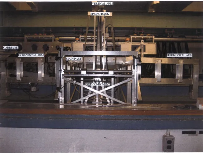
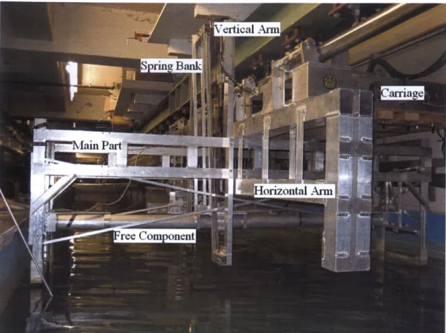
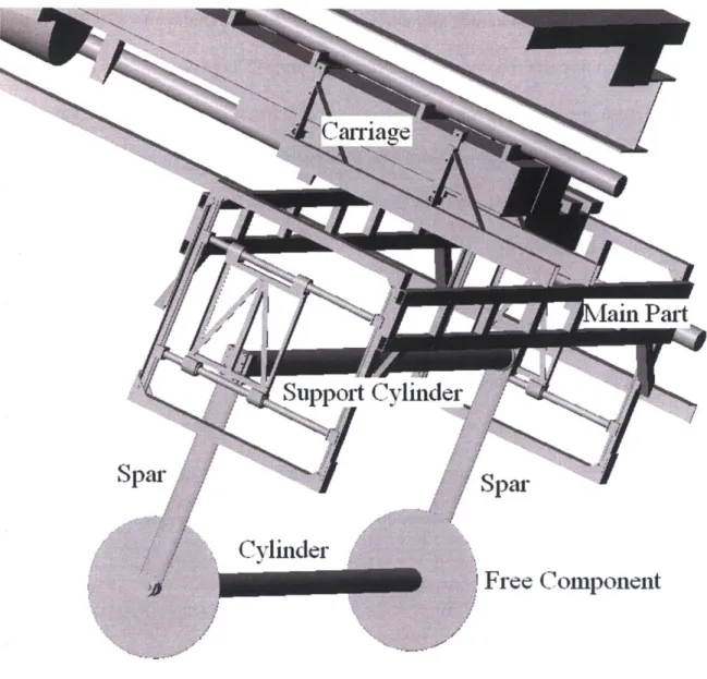
indentation would fit over the rubber stopper when the cylinder was installed. This arrangement allowed for rotation of the cylinder. For plain cylinder tests, this rotation was acceptable. For these tests, the airfoils are appended to the cylinder and rotation of the cylinder during the run would change the position of the airfoils relative to the flow. As a result, a new attachment system was developed (Figure 8.). This system involved the mounting bolt and a cross bolt. The end caps were now slotted at the specific angles that the cylinder was to be mounted at. The two spars are welded to a cylinder to provide structure and form the free component of the apparatus. The fixed structure is
attached to the carriage. The main part of the fixed structure spans the width of the tank and supports the free component of the SCR (Figure 9. and 10.). Figure 11. is a CAD model of the SCR without the arms and the spring bank. There are two arms that extend fore and aft from the main part. There is also an arm that extends vertically from the main part. These three arms represent the anchor points on the structure for the springs. The free component is attached to the main part on either end. At the attachment point, there are bearings that allow the cylinder to move in the inline and transverse directions. Attached to the free component is the spring bank. This provides the anchor point for the springs on the free component. To allow the cylinder to have free vibrations, springs are used. The springs in the transverse direction are attached from the spring bank to the vertical arm to raise the cylinder and provide most of the spring force on the cylinder. The limit of the upward spring force in the vertical direction is pulling the cylinder until it is in the middle of the bearing travel range. If a higher spring force is desired, springs are attached from the spring bank to the lower region of the main part as well as to the
vertical arm. These lower springs pull the cylinder down towards the center of the bearing travel range. The spring force in the inline direction is generated by attaching springs from the spring bank to the horizontal arms. Springs are added on both sides to keep the cylinder centered on the bearings.
Free Component
Figure 11. SCR CAD
2.2.2 Linear Motor System
The bearings are linear roller bearings and there is some friction remaining in the system due to misalignment of the SCR. Thus linear motors are used to try to counter act the friction. There is a string velocity potentiometer attached to the carriage in both the transverse and inline directions. The velocity is then read by a computer on the carriage and transforms it into a force that is exerted by the linear motor on the free component. The function is F(V)=kl+k2*VAp1. The values of ki, k2 and pl can changed so that the
damping ratio can be maintained as the friction in the SCR is variable. Due to the steep of the function through zero velocity, the force can jump to large positive and negative forces. Due to the slight inaccuracies in the potentiometer, this leads to chatter in the system. To eliminate the chatter, there is a velocity threshold built into the program. If the velocity from the potentiometer is less than the velocity threshold, there is no force exerted by the linear motors. This eliminates the chatter at the expense of lower damping ratios at lower amplitudes of motion. Therefore the velocity threshold is set as low as possible while still eliminating chatter.
The SCR allows the transverse and the inline directions to be tuned to two different natural frequencies. One issue with the arrangement is that the cross coupling of the springs. Since they are not independent in both directions, if there are springs in one direction, they will apply a force in both directions. For example, we can not have any springs in the transverse direction, but there would still be a spring force in the transverse direction due to the springs in the inline direction. Because of the coupling of motion, the linear motors were not working perfectly and thus increased the damping on the system. Since the tests on the airfoils are a comparison of different arrangements, the
SCR was locked in the inline direction and allowed to vibrate only in the transverse direction. The two dimensional system allows a more realistic representation of a riser, but the added damping makes the tests more difficult.
2.2.3 Sensors
The SCR can measure forces and displacements in the inline and transverse directions. The displacements are measured using linear potentiometers attached to the
SCR and slides over the potentiometer. The slider attracts a magnet that is within the potentiometer and the magnet moves with the slider as the free component moves. There is a voltage supplied to the sensor and a differential voltage is outputted by the sensor based on the position of the magnet. This voltage is read directly into the data acquisition system. The forces are measured by the Kistler three axis piezoelectric force sensors.
2.2.4 Large Airfoils
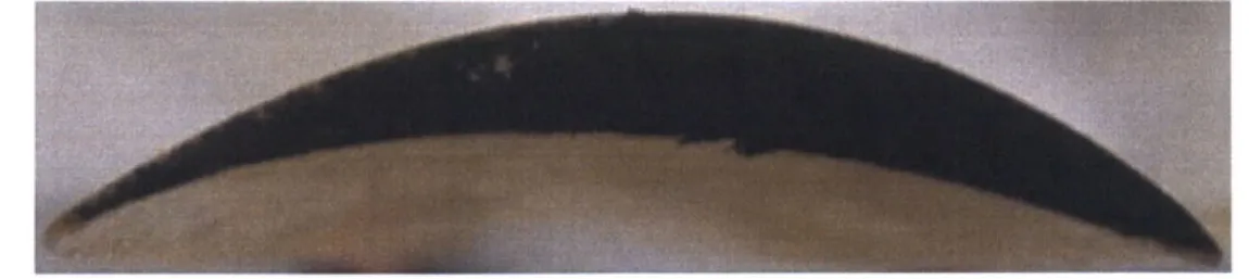
Two different airfoils were used. The first (Figure 12.) is a standard NACA section profile and camber line. The profile is a 63A010 and an a=.2 camber line.
Figure 12. Flat Airfoil Profile: 63A010 Camber line: a=.2
The second (Figure 13.) airfoil is more cambered. The meanline follows the radius of the circle around the cylinder. The profile is still the 63A010.
Figure 13. Curved Airfoil
An aluminum mold was made of each section 36 inches long. The airfoils are made by mixing epoxy with milled fiberglass. This method of airfoil construction worked well and only one foil broke. This method provided sufficient strength so that only twos supports were needed per pair of foils. The only drawback of this type of airfoil is that it
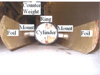
is heaver than water so the foils generally hung below the cylinder. Pipes are sized so that the inner diameter is standard. Therefore the 3 inch pipe fit over the 3 inch cylinder. The 3 inch pipe was cut into 3/8" rings and drilled with screw holes. The foils were drilled and a screw was inserted through the foil and attached to the rings (Figure 8.). Small aluminum airfoil extrusions were inserted between the airfoil and the rings to further offset the airfoils from the cylinder and also reduce the drag from the screws. The first set of rings had setscrews so that they could be clamped to the cylinder. When the airfoils were allowed to freely rotate, a new set of rings were fabricated. The rings were over bored on a lathe so that they were loosely fitting over the cylinder.
ounte Wighit
Figure 14. Arrangement
The parameters that were varied were the orientation about the cylinder, the distance of the airfoil off the cylinder and whether the foils were staggered, single, or continuous. The orientation of the cylinder is defined by the angle the screw makes with the aft centerline. This variable is called phi (9p). The airfoils were tested at three angles; 900,750, and 600. The distance of the airfoil off the cylinder (d) was either .333R or .666R. Also the two airfoils had two different chord lengths (c). Figure 9. shows the D3
Figure 15. Rigid Airfoil C3 Arrangement Dimensions
Continuous means that there were four foils and the whole cylinder was covered with foils. A pair of foils is both a foil on the top and bottom, and in this arrangement, each pair is mounted on two rings (Figure 16.).
Figure 16. Continuous Arrangement
The staggered arrangement means that the one foils is on the bottom for half the span of the cylinder and the other half of the span has an airfoil on the top. Three rings were used so that the two foils are connected together (Figure 17.).
Figure 17. Staggered Arrangement
The single arrangement is where one foil covers each half of the span. Unlike the staggered arrangement, the single arrangement are not connected together (Figure 18.).
Figure 18. Single Arrangement
Each arrangement is tested at Vrn 4, 5, 6, 7, 8, 10, 12, and 14. This allows for a good
resolution around the expected reduced velocities of vibration and checks the higher reduced velocities for any galloping phenomenon.
2.2.5
Testing Procedure
Every time the cylinder is reattached to the SCR, a pluck test and a calibration have to be performed. The pluck test is used to determine the natural frequency of the system as well as the damping ratio. The test is performed by pushing the free
component of the SCR to the bottom of the rails in the transverse direction and releasing. The cylinder is allowed to oscillate until it stops moving. The data from the transverse linear potentiometer is recorded. Using a Matlab program, the range of data is selected and it is analyzed to determine the mean natural frequency and the mean damping ratio. Plots of the time trace for the pluck test as well as a plot of damping ratio vs. A/D. The second plot is very useful in tuning the linear motor system. The constants of the transformation function can be modified to try to achieve the same damping ratio at all
A/D. Calibration tests are performed in both the transverse and inline directions. The original calibration system for the inline direction utilized pulleys. A string was attached to the cylinder and then run through a series of pulleys so that a weight could be hung. There was friction in the pulleys so that there would be residual tension in the string when a weight was hung and then removed. This gave inaccurate results for the
calibrations. A new system was developed to calibrate in the inline direction. A rod was hung from the rail parallel to the water across the width of the tank. Then a long piece of two by four is suspended from the rod into the water. An arm a third of the way down the wood created a platform where the calibration weights were placed. The weight that was placed is converted into a horizontal force at the bottom of the two by four. A string connected the two by four to the cylinder. This allowed for a frictionless system to calibrate the inline direction. The transverse direction is calibrated by suspending a weight from the cylinder. Originally, the directions were calibrated independently. Then it was found that there is cross coupling between the two directions and instead of using a single factor for each direction, a calibration matrix is used. Matlab is used to determine the matrix. During the calibration, both directions are recorded. First the drift of the force sensor is eliminated. The voltages output in each direction for the calibration for each direction are found and placed into a matrix. The forces that were applied during the calibration are placed into a second matrix. The calibration matrix is found by multiplying the force matrix by the inverse of the voltage matrix. From the test a calibration matrix is created for each of the force sensors. The calibration for the linear potentiometers is performed less frequently because unlike the force sensors, they are extremely stable. A ruler is placed next to the potentiometer and the free component is
moved a specific distance. Using Matlab, the voltage is found for each distance and the calibration is found.
Matlab is used to analyze the data. The program that was developed asks for the number of runs that want to be analyzed. Then it asks for the speeds corresponding to the runs that are being tested. Next, each run is processed. A dialog box appears where the run is selected. The drift is eliminated and the calibrations are applied to the voltages. Then a plot of the drag force is plotted and the range of data to be analyzed is then
selected. The drag coefficient and the Amplitude over Diameter ratio for the run are calculated. This is repeated for each of the runs that were specified to be analyzed. The results from the batch of runs are output as a matrix and then are placed in the
spreadsheet.
The tests were originally supposed to be with the arrangements fixed to the cylinder. Each of the arrangements was supposed to be rotated 0', 30', and 60' with respect to the flow. The first case that was tested was A3. The cylinder did not vibrate and had reduced drag. So then the project moved to a more realistic case with the airfoils allowed to freely rotate around the cylinder. To determine the position of the freely rotating airfoil, a video was taken starting with the C arrangements. A picture was captured from the video and using a CAD program, the angle of the foil was determined. The angle of the airfoil is measuring the lower airfoil and from the aft centerline similar to the position for the arrangement. Due to the weight of the airfoils, starting with the C_A arrangements, a screw was mounted to the front of the rings and used to
2.2.6 Results
The A3 arrangement was using the flat airfoils. The spacing was .333R and the orientation was 900. The airfoils were continuous. A3 was the first test that was
performed for the rigid foils in the large tank. The foils were held fixed to the cylinder. No tests were performed at other angles of attack. There was a peak in drag at Vrn 7. The A3 arrangement with the foils fixed to the cylinder was repeated. This test was performed to see if there was still an increase in drag coefficient at Vrn 7. This is the case. With the promising results of the fixed airfoil arrangement, the next step was to test a more realistic scenario. In the ocean, the flow would not always be coming in the ideal direction. Therefore a unidirectional arrangement such as the airfoils needs to be able to freely rotate around the cylinder. The next set of tests was then performed with the airfoils freely rotating around the cylinder. The hope was that the airfoils would be able to self-align themselves with the flow. The first test of A3 that was performed where the foils were allowed to rotate had a damping about 1 % with the fully foiled cylinder. There was sustained vibration from Vrn 6 to Vrn 10 when the cylinder was perturbed. The drag was slightly higher at the lower reduced velocities due to the foils being on the bottom of the cylinder. When in sustained motion, the foils would align themselves with the flow. The gains for the linear motor were reduced because when the damping was check with the bare cylinder, the motors were adding too much energy to the system. The A3
arrangement free to rotate was retested. This test was with the lower gain settings. There was sustained motion only at Vrn 6.
The Al arrangement was using the flat airfoils. The spacing was .333R and the orientation was 60'. The airfoils were continuous. The foils did not rotate so that they
were symmetrical with the centerline of the cylinder. Instead, the lower foil rotated to align itself to the flow. The upper foil was in the back of the cylinder. The drag at the lower reduced velocities is higher because the foils are hanging down. The drag was about average when compared the other arrangements. There were no vibrations for this arrangement.
The A2 arrangement was using the flat airfoils. The spacing was .333R and the orientation was 75'. The airfoils were continuous. At Vrn 6 there was sustained motion when perturbed. The foils were aligning itself with the water inflow. When there was no vibration, the lower foil aligned itself with and the upper foil was behind the cylinder. Once again the lower velocities had higher drag coefficient because the foils were hanging down below and did not align. The drag was high when compared to the other arrangements but not as high as Cl. The vibrations were also high but no the highest overall.
A4 was an arrangement that I thought was interesting to test. The A4
arrangement was using the flat airfoils. The spacing was .333R. This utilized only one foil and it was set to be the lower foil. The foil would sit near the bottom and move a
little to align itself with the flow. The drag at the lower velocities is lower than the twin foil tests because the foil is not perpendicular to the flow, but more aligned. There was
no motion in this arrangement. The drag was one of the lowest for all of the arrangements.
The A5 arrangement was using the flat airfoils. The spacing was .333R. A5 is another arrangement that utilizes a single foil. In this case, the foil remaining is the upper foil. When the foil was perturbed, the foil would flip onto the top side of the cylinder and
stay in a "sweet spot" at the top. When the cylinder was not perturbed, the foil would be behind the cylinder. There were sustained vibrations when the cylinder was perturbed at Vrn 6. Vm12 did not get the foil to flip to the top side. The drag was slightly below average for the arrangements. The vibrations were lower than most of the arrangements that had sustained vibrations.
The AlA arrangement was using the flat airfoils. The spacing was .333R and the orientation was 600. The airfoils were staggered. This was a test of AlA allowing it to freely rotate. As with the continuous case, the foil was not symmetrical about the centerline but the lower foil was aligned with the flow. This arrangement had sustained vibration over the largest range of speeds. This is similar to what was observed on the flexible cylinder. The vibrations were higher than the average for all the arrangements. The drag was also higher than most of the arrangements.
The A2A arrangement was using the flat airfoils. The spacing was .333R and the orientation was 75'. The airfoils were staggered. A2A was tested with the ability to freely rotate. There was sustained motion at Vrn 6 and 7. Similar to A2, the foils did not become aligned symmetrically about the inflow direction. This arrangement had one the highest vibrations. The drag was also above average.
The A3A arrangement was using the flat airfoils. The spacing was .333R and the orientation was 90'. The airfoils were staggered. A3A was allowed to freely rotate about the cylinder. Only at a reduced velocity of 6 was there sustained motion. The drag was also lower than A2A and AlA. These results are similar to those that were found on the flexible cylinder.
The C3 arrangement was using the curved airfoils. The spacing was .333R and the orientation was 900. The airfoils were continuous. This was the case of C3 allowed to freely rotate. The cylinder vibrated at Vrn 5 to 8 when the cylinder was perturbed and
Vrn 6 and 7 when it was not. The overall drag on the cylinder is higher than that of A3. One the other hand, the vibrations was less than the C3 arrangement. Also there was no self tailing capability exhibited. The foils generally hung towards the bottom of the cylinder. This is shown by the high angles, far from the ideal.
The C2 arrangement was using the curved airfoils. The spacing was .333R and the orientation was 75'. The airfoils were continuous. This test was of the C2
arrangement allowed to freely rotate. The cylinder vibrated at Vrn5 and Vrn 6. The drag was higher at the lower reduced velocities due to the foils not aligning with the flow. The foils did not have the self aligning characteristics as the less cambered foils. This can be seen in the high lift coefficients as the foils hung at the bottom. The foils were also far forward in relation to the ideal. This can also be confirmed by the videos. The drag was about average for most of the arrangements. It was much lower than the CI or C3 arrangement. The vibrations were also about average.
The CI arrangement was using the curved airfoils. The spacing was .333R and the orientation was 600. The airfoils were continuous. This is the Cl arrangement allowed to freely rotate. The drag is higher due to the foils not rotating into the flow. The lift is also high because of the same reason. The cylinder vibrated at Vrn 5 and 6.
The foils were unable to self align themselves with the flow. The foils were quite far forward. The drag was the highest of all the continuous foil arrangements and the second
highest of all the arrangements. This arrangement had the highest vibrations out of all the arrangements tested.
The CIA arrangement was using the curved airfoils. The spacing was .333R and the orientation was 600. The airfoils were staggered. This is the CIA arrangement free to rotate and counter balanced. The counter balancing seemed to help a little with the orientation problem. It also helped make the foils align better to reduce the drag
coefficient. Vm 5-8 had sustained motion Vrn 8 did not need to be perturbed to have the sustained motion. This arrangement is about average when compared to the other
arrangements in both drag and vibrations.
The C2A arrangement was using the curved airfoils. The spacing was .333R and the orientation was 75'. The airfoils were staggered. This is a test of the C2A
arrangement free to rotate and with the counterbalance system. The foils are further back when compared to C2 at the lower speeds, but were further forward at the higher speeds. Vm 5 had small motions when perturbed. Vm 6 and Vrn 8 had sustained motions when not perturbed. On the other hand Vm 7 did not have sustained motion when not
perturbed. I think that this arrangement is extremely sensitive to motion. The drag is about average when compared to the other staggered arrangements. The vibrations were also about average for the arrangements tested.
The C3A arrangement was using the curved airfoils. The spacing was .333R and the orientation was 90'. The airfoils were staggered. This is the C3A arrangement free to rotate and with the counter weight system. The foils were further back on the cylinder compared with C3. Also the drag was reduced across the entire speed range. There was sustained motion at Vn 5-8 when perturbed. The vibrations were about average when
compared to the other arrangements. The drag was also about average compared to the other arrangements.
The C4 arrangement was using the curved airfoils. The spacing was .333R. This was the C4 arrangement allowed to freely rotate. The drag coefficient is high because the foils did not align themselves with the flow. At Vrn5-8 there was vibration. The lift coefficient is also high due to the asymmetry of the arrangement. The foils aligned themselves far forward on the cylinder. The drag for the arrangement was higher than most of the other arrangements. The vibrations were slightly higher than average for the arrangements.
The C5 arrangement was using the curved airfoils. The spacing was .333R. This is the C5 arrangement. The foil angles were a little further forward than perpendicular. The drag was much higher than the A case. The foils also had high lift due to the
asymmetry. The cylinder vibrated at Vrn 5-7 when perturbed and Vrn7 when it was not perturbed. This arrangement showed the highest vibrations of all the single foil
arrangements and had highest drag compared to the other arrangements.
The C6 arrangement was using the curved airfoils. The spacing was .333R. One foil is oriented as the lower foil and the other foil is oriented as the upper foil. This is the C6 arrangement allowed to freely rotate. The drag was higher than the A configuration. The foils were a little farther forward than perpendicular. Vibration occurred at Vrn 5-8
when it was perturbed and Vrn 6 when it was not perturbed. The vibrations were comparable to the other C single foil arrangements. The drag was about the same as the C4 arrangement and slightly less than the C5 arrangement.