Publisher’s version / Version de l'éditeur:
Journal of the Electrochemical Society, 157, 1, pp. B125-B129, 2010
READ THESE TERMS AND CONDITIONS CAREFULLY BEFORE USING THIS WEBSITE. https://nrc-publications.canada.ca/eng/copyright
Vous avez des questions? Nous pouvons vous aider. Pour communiquer directement avec un auteur, consultez la première page de la revue dans laquelle son article a été publié afin de trouver ses coordonnées. Si vous n’arrivez pas à les repérer, communiquez avec nous à [email protected].
Questions? Contact the NRC Publications Archive team at
[email protected]. If you wish to email the authors directly, please see the first page of the publication for their contact information.
NRC Publications Archive
Archives des publications du CNRC
This publication could be one of several versions: author’s original, accepted manuscript or the publisher’s version. / La version de cette publication peut être l’une des suivantes : la version prépublication de l’auteur, la version acceptée du manuscrit ou la version de l’éditeur.
For the publisher’s version, please access the DOI link below./ Pour consulter la version de l’éditeur, utilisez le lien DOI ci-dessous.
https://doi.org/10.1149/1.3253653
Access and use of this website and the material on it are subject to the Terms and Conditions set forth at
Evaluation of metal supported ceria based solid oxide fuel cell
fabricated by wet powder spray and sintering
Oishi, Naoki; Yoo, Yeong
https://publications-cnrc.canada.ca/fra/droits
L’accès à ce site Web et l’utilisation de son contenu sont assujettis aux conditions présentées dans le site LISEZ CES CONDITIONS ATTENTIVEMENT AVANT D’UTILISER CE SITE WEB.
NRC Publications Record / Notice d'Archives des publications de CNRC:
https://nrc-publications.canada.ca/eng/view/object/?id=5662fedc-0235-4b36-adb1-91c5417c6fd0
https://publications-cnrc.canada.ca/fra/voir/objet/?id=5662fedc-0235-4b36-adb1-91c5417c6fd0
Evaluation of Metal Supported Ceria Based Solid Oxide Fuel
Cell Fabricated by Wet Powder Spray and Sintering
Naoki Oishizand Yeong Yoo
Institute for Chemical Process and Environmental Technology, National Research Council Canada, Ottawa, Ontario K1A 0R6, Canada
A ceria based solid oxide fuel cell was fabricated onto a porous stainless steel support by sintering process. The metal supported cell was composed of a porous AISI430 support, a Ni–Ce0.8Y0.2O1.9 anode, a Ce0.9Gd0.1O1.95 electrolyte, and a La0.6Sr0.4Co0.2Fe0.8O3cathode. A cell was tested at 600°C for up to 2700 h on humidified argon balanced hydrogen and air. The cell showed no signs of degradation over 1200 h at low current densities of 0.16 and 0.24 A cm−2; however, under a high current density of 0.32 A cm−2, the cell voltage dropped by 25% in 1400 h. Impedance measurements showed a sharp increase in polarization resistance that could be associated with the cathode. Ohmic resistances from the oxide scale and electrodes did not significantly contribute to the overall resistance, while electrode polarization resistance accounted for more than half of the overall resistance.
© 2009 The Electrochemical Society. 关DOI: 10.1149/1.3253653兴 All rights reserved.
Manuscript submitted August 5, 2009; revised manuscript received September 14, 2009. Published November 13, 2009. This was Paper 1517 presented at the Vienna, Austria, Meeting of the Society, October 4–9, 2009.
The early development of metal supported solid oxide fuel cells 共SOFCs兲 in the middle of the 1960s demonstrated that zirconia cells with a variety of porous metal supports made of nickel or stainless steel were operational at 710–800°C.1,2In the 1980s, nickel sup-ported thin zirconia cells fabricated by vacuum evaporation and back-etch were reported to be operational at 500–700°C.3-5 How-ever, it was not until the 1990s that a couple of research organiza-tions developed metal supported SOFCs with reasonable cell characteristics.6-9The metal support structure using a ferritic stain-less steel material allowed for enhancement of the mechanical strength of cells, improving the redox stability of cell stacks and minimizing the usage of costly electrode and electrolyte materials.10 In recent years, there has been an increasing number of research activities on metal supported SOFCs with ferritic stainless steel materials.11-16
It is important to establish inexpensive technologies for manu-facturing to further reduce costs. In fabricating metal supported SOFCs, using conventional ceramic manufacturing technologies is advantageous from an economic perspective. The conventional ce-ramic technologies in producing cece-ramic bodies with powder mate-rials include molding, pressing, and sintering, which are all afford-able technologies. The range of thickness of cell components, i.e., the cathode, electrolyte, and anode, is projected to lie within 1–30 m; therefore, wet powder spray technology17,18is consid-ered one of the candidates for forming thin cell components on a support from a viewpoint of thickness controllability. By replacing the molding process in conventional ceramic manufacturing nologies with a spraying process, such ceramic manufacturing tech-nologies can be exploited to make thin layers on a support.
The objective of this study is to fabricate stainless steel sup-ported SOFCs by using such a modified ceramic manufacturing technology involving the wet powder spray and subsequent sintering step with an attempt to operate cells at a lower temperature of 600°C, to check their long-term stability, and to evaluate cell com-ponents based on electrical resistivity.
Experimental
Commercially available porous AISI430 stainless steel 共Fe-17Cr兲 sheets made by powder metallurgy were used as a support. The porosity of the sheet was about 15%. A porous stainless steel support was prepared in a 25 mm diameter disk form, 1.2 mm thick. The porous supports were cleaned in organic solvents and passivated in nitric acid before fabricating cell structures on them.
A trilayer of anode, electrolyte, and cathode was fabricated as
follows.19First, an anode layer was deposited onto the surface of a porous support by wet powder spray17,18using a colloidal suspen-sion. The sprayed anode layer was pressed to have the sprayed sur-face smooth, and then prefired at 900°C for 1 h. Subsequently, an electrolyte layer was sprayed in a similar manner to the anode spray. After a binder burnout process at 500°C, the electrolyte layer was isostatically pressed at 345 MPa to achieve a high level of packing density and then sintered at 1050°C in a nonoxidizing atmosphere for 1 h. A cathode layer was finally attached by spraying and firing at 850°C for 3 h. Suspensions were prepared with an oxide powder, organic agents 共binder and surfactant兲, and an alcohol medium. 55 wt % NiO–45 wt % Ce0.8Y0.2O1.9composite 共Ni-CY82兲 was used
for the anode material and Ce0.9Gd0.1O1.95共CG91兲 was used for the
electrolyte. The cathode was La0.6Sr0.4Co0.2Fe0.8O3共LSCF6428兲. In
this work, zirconium 共0.5–1 cation %兲 was used as a sintering in-hibitor for the anode for the purpose of keeping the anode layer porous during the electrolyte sintering, whereas iron 共0.5–1 cation %兲 was used as a sintering aid20to densify the electrolyte layer.
To evaluate polarization resistances in the electrodes, impedance measurements were carried out in the temperature range 400–600°C on symmetrical cells: an LSCF6428 cathode | CG91 electrolyte | LSCF6428 cathode cell, and a Ni-CY82 anode | CG91 electrolyte | Ni-CY82 anode cell, with an excitation voltage of 10 mV over the frequency range 1 ⫻ 106to 1 ⫻ 10−3 Hz. Electrodes were depos-ited by spray onto 13 mm diameter, 0.9 mm thick CG91 electrolyte disks. For anodes, due to technical difficulties in realizing the fab-rication conditions similar to those for cell manufacturing, an anode layer was sprayed onto both sides of an electrolyte disk that was sintered at 1050°C, and then fired at the same temperature after pressing. In the cell manufacturing, the deposited anode, which was prefired at 900°C, was cofired with the electrolyte at 1050°C after pressing.
The cell fabricated on a porous stainless steel support was tested by using a galvanostat on humidified argon balanced hydrogen and air at 600°C. Fuel utilization was kept below 10%. A schematic diagram of the fuel cell test rig is shown in Fig.1. The temperature was monitored underneath the porous support in the fuel atmo-sphere. In the cathode side, the surface of the Fe-17Cr stainless steel support was coated with either the CG91 electrolyte or ceramic ce-ments so that there was no direct exposure to air 共negligible chro-mium vapor species in the cathode兲. The current density was calcu-lated based on the area of the cathode with a smaller diameter than the electrolyte. Impedance measurements were also performed dur-ing testdur-ing. After testdur-ing, microanalysis usdur-ing a scanndur-ing electron microscope 共SEM兲 was carried out on cross sections of a tested sample.
z
Results and Discussion
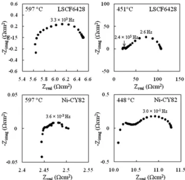
Estimation of polarization resistance by impedance measure-ments of symmetrical cells.— Impedance spectra 共Nyquist plots兲 for the LSCF6428 cathode and the Ni-CY82 anode on CG91 electro-lytes are shown in Fig.2. Air was used as a cathode gas, and hu-midified argon balanced 50% hydrogen 共wet Ar–50% H2兲 was used
as an anode gas. The impedance spectrum for LSCF6428 at 597°C is made of one arc with its peak at 3.3 ⫻ 103 Hz and an inductive
response at high frequency, while at a low temperature two well-defined arcs are observed. Although two overlapping arcs at high frequency 共peak at ⬃103 Hz兲 and low frequency 共peak at ⬃10 Hz兲,
attributing the former to charge transfer and the latter to diffusion of oxygen species, are reported,21,22the low frequency arc is not dis-tinguishable in this impedance spectrum. Like the LSCF6428, the impedance spectrum for Ni-CY82 at 597°C seems to consist of one distorted arc with its peak at 3.6 ⫻ 10−3 Hz and an inductive com-ponent, while at a low temperature there appears to be another arc at high frequency as well as a low frequency arc. Literature on imped-ance measurements for cermet anode–ceria electrolyte systems is limited; impedance spectra for copper or nickel cermet anodes on ceria electrolytes are reported to have a low frequency arc 共⬃10−3 Hz兲.23,24
In this work, polarization resistance, Rpol, was defined by the
difference in the two x-intercepts plotted or by fitting a semicircle to a low frequency arc in obtaining the length of the cord on the x-axis where two arcs were noticeable at low temperatures. Although im-pedance spectra in the temperature range tested contained induc-tance contributions, no calibration was made to eliminate the effect of inductance, e.g., at 597°C 0.84 ⍀ cm2 for LSCF6428 and
0.05 ⍀ cm2for Ni-CY82. As shown in Fig.3, Arrhenius plots of Rpol are linear, estimating activation energies at 1.7 eV for
LSCF6428 and 1.0 eV for Ni-CY82 on CG91 electrolytes. Over the temperature range tested, the Ni-CY82 anode has at least 1 order of magnitude lower polarization resistance than the LSCF6428 cath-ode. There are many reports regarding the polarization resistance and activation energy of the La0.6Sr0.4Co0.2Fe0.8O3 cathode–ceria
electrolyte systems by using impedance spectroscopy;21,22,25-28 how-ever, polarization resistances are widely varied, especially in the temperature range 500–600°C where there is as much as 1 order of magnitude of difference at the same temperature, e.g., at 600°C from 0.3 to 4 ⍀ cm2, while activation energies obtained on
Arrhen-ius plots lie within a range of 1.1–1.7 eV. Compared with these, our estimated polarization resistance is relatively low, about 0.8 ⍀ cm2
at 600°C with the activation energy being high 共1.7 eV兲. Little is known on cermet anode–ceria electrolyte systems. The activation energy calculated for Ni-CY82 共1.0 eV兲 agrees with a value of 0.95– 0.96 eV for a Ni–Ce0.8Sm0.2O1.9cermet anode on a Ce0.8Sm0.2O1.9
electrolyte system characterized by a three-electrode configuration.29 However, the reported polarization resistance is about 0.6 ⍀ cm2at 600°C, which is more than 1 order of
magni-tude higher than our obtained resistance 共0.05 ⍀ cm2兲. In this
work, the firing temperature was lower, and isostatic pressing was Electrolyte
Ceramic cement
Cathode
Anode
Stainless steel support Ceramic tube Fuel Air Not to scale Pt lead to galvanotat Pt lead to galvanotat T. C.
Figure 1.Schematic diagram of a fuel cell test rig placed in a furnace.
Figure 2.Impedance spectra 共Nyquist plots兲 for the LSCF6428 cathode and the Ni-CY82 anode on CG91 electrolytes. The temperature and peak fre-quency are shown.
Figure 3. Arrhenius plots of Rpolfor the LSCF6428 cathode and the Ni-CY82 anode.
B126 Journal of The Electrochemical Society, 157 共1兲 B125-B129 共2010兲 B126
applied to improve the bonding between the electrolyte and the an-ode before firing; therefore, these processing conditions are thought to retain high surface area to provide lower polarization resistance. Long-term testing of a cell fabricated on a porous stainless steel support.— A cell fabricated on a porous stainless steel support was about 20 m in anode thickness, about 10 m in electrolyte thick-ness, and about 25 m in cathode thickness. Thicknesses were mea-sured with the step height around the edge of each layer by an optical microscope. The density of the sintered electrolyte remained unclear due to variability in observed thickness; however, image analysis on surface SEM micrographs indicated a volume density of 96–98%. The open-circuit voltage, Voc, was about 0.84 V at 600°C
on wet Ar–50% H2and air.
Figure4shows the voltage change in a cell tested for up to 2700 h under different galvanostatic operations: 0.16, 0.24, and 0.32 A cm−2. There is no noticeable voltage degradation for about
1200 h after 100 h during the 0.16 and 0.24 A cm−2operations.
After the current density was increased from 0.24 to 0.32 A cm−2,
the cell started to show voltage degradation over time, and the cell voltage dropped by 25% in the following 1400 h.
Current density–voltage characteristics taken at 20 and 1000 h during the 0.16 A cm−2galvanostatic operation, at 1375 h during
the 0.24 A cm−2 operation, and at 2100 and 2700 h during the
0.32 A cm−2 operation are shown in Fig. 5. During the
0.16 A cm−2galvanostatic operation, V
ocremained the same,
ap-proximately 0.84 V, while the current density was slightly increased.
When the hydrogen concentration was changed from 50 to 75% at 1375 h, there appeared to be a great increase in current density with Voc being almost similar. In our preliminary fuel cell test
experi-ments at 600°C, Vocwas found to gradually increase with time when
fuel started to be fed into the anode; in addition, high concentration fuel had an impact on the rate of Vocgeneration, and it was therefore
thought that the nickel oxide in the anode deposited onto such a thick porous support 共1.2 mm兲 with a low porosity 共⬃15%兲 is not readily reduced to increase porosity at 600°C. Accordingly, the in-crease in current density seen in Fig. 5 can be attributed to the improved diffusivity of H2 and H2O in the anode side, which is
associated with concentration polarization. During the 0.32 A cm−2
galvanostatic operation from 1375 to 2700 h, Vocas well as current
density decreased.
Figure6shows the impedance spectrum under open-circuit volt-age condition at different times. At 20 and 1000 h, the spectra are made of two arcs at high and low frequencies, which are similar in size. As expected from slopes near Voc on the current density–
voltage characteristics in Fig.5, the overall resistance obtained from impedance measurements remained almost unchanged, about 0.73 ⍀ cm2. The impedance spectrum at 1375 h on 75% H
2has a
smaller arc at low frequency than that at 20 and 1000 h measured on 50% H2. In our separate work30using porous supports made by laser
drilling, which could provide high gas permeability due to straight open pores in the thin 共0.25 mm兲 support with high porosity 共20%兲, the arc at low frequency was merged to the high frequency arc; therefore, the low frequency arc is thought to be associated with polarization in the anode side, especially concentration polarization 共in anode and porous support兲. In fact, a cell fabricated on the laser-drilled porous support was found to deliver more current with good linearity with voltage until a high current density 共⬎0.5 A cm−2兲,
which indicated the importance of gas transport in porous supports in decreasing concentration polarization. In contrast to the peak fre-quency of the arc for the symmetrical anode 共⬃10−3 Hz兲 shown in
Fig. 2, the impedance spectrum for the symmetrical cathode ap-peared to have an arc with its peak lying at a higher frequency, 103 Hz range; therefore, the high frequency arc with a peak at a
range 102–103 Hz in the impedance spectrum for a cell is thought to have a correlation with cathode. After 1375 h, the arc at the high frequency seems to grow, with its peak frequency shifting toward the low frequency from 5.0 ⫻ 102 Hz at 1375 h to 1.6 ⫻ 102 Hz at
2700 h, and the overall resistance increases by 0.19 ⍀ cm2. In the
nickel–cermet anode supported zirconia cells tested for 1500 h at 750°C at various current densities, the high frequency arc is re-ported to increase with increasing current densities.31Compared to the change in the overall resistance, the ohmic resistance change is only 0.05 ⍀ cm2, and high current density operation is found to
deteriorate polarization resistance. Because the range of the high frequency arc observed on a cell under open potential is closer to Figure 4. Voltage of a stainless steel supported ceria based cell at 600°C
under different galvanostatic operations.
Figure 5.Current density–voltage characteristics at 600°C at different times. Hydrogen fuel concentration is shown in percent.
Figure 6. Impedance spectra at 600°C under open-circuit condition at dif-ferent times. Hydrogen fuel concentration is shown in percent.
that of an arc observed on the cathode symmetrical cell, the high frequency arc is thought to reflect polarization in the cathode rather than polarization in the anode. The degradation under the 0.32 A cm−2operation where the high frequency arc is growing in
size is thought to be caused by some change in the cathode, which could also explain the drop in Voc from 0.84 to 0.79 V due to
in-creased electrode polarization.
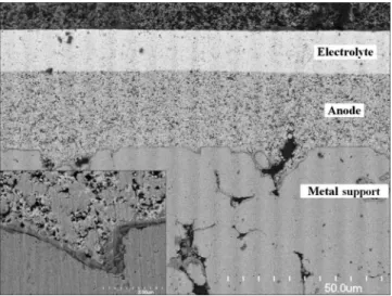
Evaluation of resistive cell components.— The cross-sectional SEM micrographs of the cell tested for 2700 h are shown in Fig.7. The thickness of the Ni-CY82 anode is 23–26 m, and the CG91 electrolyte is 13–14 m. Although the cathode is not shown due to partial delamination during sample preparation, the thickness range was 25–30 m. A thermally grown oxide scale on the Fe–17Cr porous stainless steel support is seen 共inset of Fig. 7兲, but in the stainless steel phase underneath the oxide scale, there is no continu-ous inner oxide phase like SiO2.
Assuming that the oxide scale is made of pure Cr2O3, from the
resistivity data for Cr2O3,32the area specific resistance of the oxide
scale with a thickness of less than 0.5 m is calculated to be less than 1 ⫻ 10−3 ⍀ cm2 at 600°C. In general, AISI430 has
manga-nese as a minor element 共up to 1 wt %兲; therefore, the resistivity of the oxide scale can be decreased by manganese doping, which would be the case for this oxide scale grown. The electrical resis-tivity of the stainless steel is also negligible 共Ⰶ10−3 ⍀ cm2兲.
Because the Ni-CY82 anode is estimated to have approximately 42 vol % nickel and 58 vol % Ce0.8Y0.2O1.9, the matrix of this anode
layer is made up of Ce0.8Y0.2O1.9. Resistivity measurement of a
sintered Ni-CY82 disk showed that it has a metallic behavior in the temperature range 550–650°C in wet Ar–50% H2, and the resistivity
at 600°C was about 1.9 ⍀ cm. The 23–26 m thick anode layer is expected to be below 5 ⫻ 10−3 ⍀ cm2in area specific resistance.
According to earlier reports,33,34the total resistivity 共lattice plus grain-boundary contributions兲 for Ce0.9Gd0.1O1.95is 62–70 ⍀ cm at
600°C in air, and the area specific resistance of a 13–14 m thick electrolyte is calculated to be 0.08–0.1 ⍀ cm2in air. However, the
resistivity of cerium oxide is decreased with decreasing oxygen par-tial pressure, pO2, due to the occurrence of electronic conductivity
共Ce4+
→ Ce3++ e−兲. It is difficult to obtain the resistivity of a ceria electrolyte layer under a pO2 gradient. The electrolyte layer may
have a resistivity close to that of the anode. As can be roughly estimated from the impedance spectra of symmetrical cells by as-suming that the lower x-axis intercept corresponds to the resistance of a ceria electrolyte disk, the resistivity in air is 125 ⍀ cm, while
the resistivity in wet Ar–50% H2 is 50 ⍀ cm, which is less than
half of the resistivity in air. Accordingly, the electrolyte’s resistance would not exceed 0.1 ⍀ cm2in the form of a cell.
The resistivity of La0.6Sr0.4Co0.2Fe0.8O3 is reported
35
to be 2.9 ⫻10−3 ⍀ cm at 600°C in air, and the area specific resistance of a
25–30 m thick cathode is well below 1 ⫻ 10−5 ⍀ cm2, assuming
a porosity of 30%.
From the impedance spectrum at 20 h, ohmic and polarization resistances are 0.32 and 0.41 ⍀ cm2, respectively. The ohmic
resis-tances of the oxide scale, the anode, and cathode layers are low enough so that these components would not contribute significantly to the ohmic resistance in a cell. The electrolyte layer might well account for most of the ohmic resistance. However, the measured ohmic resistance of 0.32 ⍀ cm2appears to be greater than the
es-timate, less than 0.1 ⍀ cm2; there needs to be some unknown
re-sistive component, which is yet to be identified to explain this in-consistency. In contrast, the polarization resistance of 0.41 ⍀ cm2
obtained on the impedance measurement under open-circuit voltage condition is less than half of the value of 0.89 ⍀ cm2 that was compiled with the anode and cathode contributions 共anode, 0.05 ⍀ cm2 and cathode, 0.84 ⍀ cm2兲 obtained on symmetrical
cells. From a polarization point of view, the cell appeared to perform better than expected, while this cell did not perform as good as the expectation from an ohmic resistance perspective, but the cell was found to show characteristics better than expected; 0.73 ⍀ cm2on
a cell over 0.99 ⍀ cm2based on estimates. Different from imped-ance measurements on symmetrical cells where there is no steady current except for a current responding to the applied signal voltage, during the impedance measurement under open-circuit voltage on a thin ceria based cell, there is a leak current due to its electronic conductivity; therefore, it is thought that the electrodes, especially the cathode, are already activated by its leak current, leading to a lower polarization resistance during the measurement.
In the cell configuration of the porous AISI430 stainless steel support, the Ni-CY82 anode, the CG91 electrolyte, and the LSCF6428 cathode, ohmic resistances from the oxide scale on the support, the anode, and the cathode have little impact on the overall resistance. It is not sufficient to explain the measured ohmic resis-tance by using the estimated electrolyte contribution. The polariza-tion resistance is found to account for more than half of the overall resistance, and the polarization resistance is thought to be dominated by cathode.
Conclusions
A stainless steel supported SOFC was made by the wet powder spray and sintering route. The open-circuit voltage of a 13-14 µm thick ceria based cell was about 0.84 V at 600°C on humidified argon balanced 50% hydrogen and air. There was no noticeable voltage degradation over 1200 h under the 0.16 and 0.24 A cm−2
galvanostatic operations; however, under the 0.32 A cm−2 opera-tion, the cell voltage dropped by 25% in 1400 h. Impedance mea-surements during the long-term test showed an increase in polariza-tion resistance that could be associated with the cathode. In the stainless steel supported ceria based cells operated at 600°C, ohmic resistances from the oxide scale, anode, and cathode do not signifi-cantly contribute to the overall resistance, while polarization resis-tance, presumably mainly from the cathode, was found to account for more than half of the overall resistance.
Acknowledgments
The authors gratefully acknowledge the financial support pro-vided by the Program of Energy Research and Development 共PERD兲-Distributed Energy Resources 共DER兲 Program in Canada.
National Research Council Canada assisted in meeting the publication costs of this article.
References
1. K. R. Williams and J. G. Smith, U.K. Pat. GB1049428 共1966兲. 2. K. R. Williams and J. G. Smith, U.S. Pat. 3,464,861 共1969兲. Figure 7.SEM micrograph of a cross section of a stainless steel supported
ceria based cell tested at 600°C for 2700 h. The interface region between the stainless steel support and the Ni-CY82 anode is shown in the inset.
B128 Journal of The Electrochemical Society, 157 共1兲 B125-B129 共2010兲 B128
3. T. Namikawa, Y. Yamazaki, I. Saitoh, T. Kanai, S. Sumiya, and M. Sato, Denki Kagaku oyobi Kogyo Butsuri Kagaku, 52, 714 共1984兲.
4. T. Ando, T. Namikawa, and Y. Yamazaki, Denki Kagaku oyobi Kogyo Butsuri Kagaku, 54, 614 共1986兲.
5. T. Namikawa, T. Ando, H. Michibata, and Y. Yamazaki, Denki Kagaku oyobi Kogyo Butsuri Kagaku, 55, 712 共1987兲.
6. T. Okuo, S. Nagata, Y. Kaga, Y. Kasuga, A. Momma, K. Tsukamoto, and F. Uchiyama, in The First European Solid Oxide Fuel Cell Forum, U. Bossel, Editor, Vol. 2, p. 909, European SOFC Forum Proceedings Series, Oberronhrdorf, Swit-zerland 共1994兲.
7. S. Nagata, T. Okuo, Y. Kaga, Y. Kasuga, K. Momma, K. Tsukamoto, and F. Uchiyama, in The Fourth International Symposium on Solid Oxide Fuel Cells, M. Dokiya, O. Yamamoto, H. Tagawa, and S. C. Singhal, Editors, PV 95-1, p. 221, The Electrochemical Society Proceedings Series, Pennington, NJ 共1995兲. 8. M. Lang, R. Henne, G. Schiller, and N. Wagner, in The Fifth International
Sym-posium on Solid Oxide Fuel Cells, U. Stimming, S. C. Singhal, H. Tagawa, and W. Lehnert, Editors, PV 94-40, p. 461, The Electrochemical Society Proceedings Se-ries, Pennington, NJ 共1997兲.
9. G. Schiller, R. Henne, and M. Lang, in The Fifth International Symposium on Solid Oxide Fuel Cells, U. Stimming, S. C. Singhal, H. Tagawa, and W. Lehnert, Editors, PV 97-40, p. 635, The Electrochemical Society Proceedings Series, Pennington, NJ 共1997兲.
10. P. Bance, N. P. Brandon, B. Girvan, P. Holbeche, S. O’dea, and B. C. H. Steele, J. Power Sources, 131, 86 共2004兲.
11. T. Franco, Z. Ilhan, M. Lang, G. Schiller, and P. Szabo, in The Ninth International Symposium on Solid Oxide Fuel Cells, S. C. Singhal and J. Mizusaki, Editors, PV 2005-07, p. 344, The Electrochemical Society Proceedings Series, Pennington, NJ 共2005兲.
12. Y. B. Matus, L. C. DeJonghe, C. P. Jacobson, and S. J. Visco, Solid State Ionics, 176, 443 共2005兲.
13. C. Lee and J. Bae, J. Power Sources, 176, 62 共2008兲.
14. M. C. Tucker, G. Y. Lau, C. P. Jacobson, L. C. DeJonghe, and S. J. Visco, J. Power Sources, 175, 447 共2008兲.
15. R. Hui, J. O. Berghaus, C. Deces-Petit, W. Qu, S. Yick, J.-G. Legoux, and C. Moreau, J. Power Sources, 191, 371 共2009兲.
16. S. Hui, D. Yang, Z. Wang, S. Yick, C. Deces-Petit, W. Qu, A. Tuck, R. Maric, and D. Ghosh, J. Power Sources, 167, 336 共2007兲.
17. K. Wippermann, U. Stimming, H. Jansen, and D. Stover, in The Third International Symposium on Solid Oxide Fuel Cells, S. C. Singhal and H. Iwahara, Editors, PV 93-4, p. 180, The Electrochemical Society Proceedings Series, Pennington, NJ 共1993兲.
18. R. Wilkenhoner, W. Mallener, H. P. Buchkremer, T. Hauber, and U. Stimming, in The Second European Solid Oxide Fuel Cell Forum, B. Thorstensen, Editor, p. 279,
European SOFC Forum Proceedings Series, Oberronhrdorf, Switzerland 共1996兲. 19. N. Oishi, Y. Yoo, and I. Davidson, ECS Trans., 7共1兲, 781 共2007兲.
20. C. Kleinlogel and L. J. Gauckler, in The Sixth International Symposium on Solid Oxide Fuel Cells, M. Dokiya and S. C. Singhal, Editors, PV 99-19, p. 225, The Electrochemical Society Proceedings Series, Pennington, NJ 共1999兲.
21. J. A. Lane, P. H. Middleton, H. Fox, B. C. H. Steele, and J. A. Kilner, in The Second International Symposium on Ionic and Mixed Conducting Ceramics, T. A. Ramanarayanan, W. L. Worrell, and H. L. Tuller, Editors, PV 94-12, p. 489, The Electrochemical Society Proceedings Series, Pennington, NJ 共1994兲.
22. V. Dusastre and J. A. Kilner, Solid State Ionics, 126, 163 共1999兲.
23. S. Baron, N. Brandon, A. Atkinson, B. Steele, A. Bauen, and D. Hart, in The Fifth
European Solid Oxide Fuel Cell Forum, J. Huijsmans, Editor, Vol. 1, p. 499,
European Fuel Cell Forum Proceedings Series, Oberronhrdorf, Switzerland 共2002兲. 24. E. Ramirez-Zabrera, A. Atkinson, N. Brandon, and B. Steele, in The Fifth Euro-pean Solid Oxide Fuel Cell Forum, J. Huijsmans, Editor, Vol. 1, p. 531, European Fuel Cell Forum Proceedings Series, Oberronhrdorf, Switzerland 共2002兲. 25. J. A. Lane, S. Adler, P. H. Middleton, and B. C. H. Steele, in The Fourth
Interna-tional Symposium on Solid Oxide Fuel Cells, M. Dokiya, O. Yamamoto, H.
Tagawa, and S. C. Singhal, Editors, PV 95-1, p. 584, The Electrochemical Society Proceedings Series, Pennington, NJ 共1995兲.
26. D. Waller, J. A. Lane, J. A. Kilner, R. J. Chater, P. S. Manning, and B. C. H. Steele, in The Second European Solid Oxide Fuel Cell Forum, B. Thorstensen, Editor, Vol. 2, p. 737, European Fuel Cell Forum Proceedings Series, Oberronhrdorf, Switzer-land 共1996兲.
27. J.-M. Bae and B. C. H. Steele, Solid State Ionics, 106, 247 共1998兲.
28. J. M. Ralph, C. Rossignol, and R. Kumar, J. Electrochem. Soc., 150, A1518 共2003兲.
29. S. Wang, T. Kato, S. Nagata, T. Honda, T. Kaneko, N. Iwashita, and M. Dokiya, in The Fourth European Solid Oxide Fuel Cell Forum, A. J. McEvoy, Editors, Vol. 2, p. 479, European Fuel Cell Forum Proceedings Series, Oberronhrdorf, Switzerland 共2000兲.
30. N. Oishi and Y. Yoo, ECS Trans., 25共2兲, 739 共2009兲.
31. A. Hagen, R. Barfod, P. V. Hendriksen, Y.-L. Liu, and S. Ramousse, in The Ninth International Symposium on Solid Oxide Fuel Cells, S. C. Singhal and J. Mizusaki, Editors, PV 2005-07, p. 503, The Electrochemical Society Proceedings Series, Pennington, NJ 共2005兲.
32. A. Holt and P. Kofstad, Solid State Ionics, 100, 201 共1997兲. 33. T. Kudo and H. Obayashi, J. Electrochem. Soc., 123, 415 共1976兲.
34. S. Wang, T. Kobayashi, M. Dokiya, and T. Hashimoto, J. Electrochem. Soc., 147, 3606 共2000兲.
35. L. W. Tai, M. M. Nasrallah, H. U. Anderson, D. M. Sparlin, and S. R. Sehlin, Solid State Ionics, 76, 273 共1995兲.