Publisher’s version / Version de l'éditeur:
Vous avez des questions? Nous pouvons vous aider. Pour communiquer directement avec un auteur, consultez la première page de la revue dans laquelle son article a été publié afin de trouver ses coordonnées. Si vous n’arrivez pas à les repérer, communiquez avec nous à PublicationsArchive-ArchivesPublications@nrc-cnrc.gc.ca.
Questions? Contact the NRC Publications Archive team at
PublicationsArchive-ArchivesPublications@nrc-cnrc.gc.ca. If you wish to email the authors directly, please see the first page of the publication for their contact information.
https://publications-cnrc.canada.ca/fra/droits
L’accès à ce site Web et l’utilisation de son contenu sont assujettis aux conditions présentées dans le site LISEZ CES CONDITIONS ATTENTIVEMENT AVANT D’UTILISER CE SITE WEB.
8th Canadian Marine Hydromechanics and Structures Conference [Proceedings],
2007
READ THESE TERMS AND CONDITIONS CAREFULLY BEFORE USING THIS WEBSITE.
https://nrc-publications.canada.ca/eng/copyright
NRC Publications Archive Record / Notice des Archives des publications du CNRC :
https://nrc-publications.canada.ca/eng/view/object/?id=45951114-76c6-4ecd-a0d3-2b0336f96547
https://publications-cnrc.canada.ca/fra/voir/objet/?id=45951114-76c6-4ecd-a0d3-2b0336f96547
Archives des publications du CNRC
This publication could be one of several versions: author’s original, accepted manuscript or the publisher’s version. / La version de cette publication peut être l’une des suivantes : la version prépublication de l’auteur, la version acceptée du manuscrit ou la version de l’éditeur.
Access and use of this website and the material on it are subject to the Terms and Conditions set forth at
Gap effect on performance of podded propulsors in straight and static
azimuthing conditions
Gap Effect on Performance of Podded Propulsors in
Straight and Static Azimuthing Conditions
Islam M
1, MacNeill A
2, Veitch B
1, Akinturk A
3and Liu P
31Faculty of Engineering and Applied Science, Memorial University of Newfoundland
St. John’s, NL, A1B 3X5, Canada
2Design engineer, Oceanic Consulting Corporation
St. John's, NL, A1B 2X5, Canada
3
Institute for Ocean Technology, National Research Council Canada St. John’s, NL, A1B 3T5, Canada
Email: islam@engr.mun.ca
A
BSTRACTThe paper presents preliminary results of an experimental study on the effect of gap distance on propulsive characteristics of puller podded propulsors in straight course and static azimuthing open water conditions. The gap distance is the axial distance between the rotating (propeller) and stationary (pod) part of a podded propulsor. The propeller thrust and torque, unit forces and moments in the three-coordinate directions of a podded unit were measured using a custom designed pod dynamometer in puller configurations with varied operating conditions. The model propulsor was tested at the gap distances of 0.3%, 1% and 2% of propeller diameter for a range of advance coefficients combined with the range of static azimuthing angles from +20° to –20° in a 10° increment. The results show that the gap distance does not have significant effect on propeller torque in straight course conditions, but has effects in azimuthing conditions. The propeller thrust and efficiency were influenced by the change of gap distance and the effects were more obvious at high azimuthing angles and high advance coefficient values. The unit thrust and efficiency, transverse and vertical forces, as well as moments in three coordinate directions were not influenced by the gap distance, taking into account the uncertainty in the measurements, both in straight course and azimuthing conditions.
1.
INTRODUCTIONAlthough research has been done on podded propellers for over three decades [1], this propulsion system type was introduced to the marine industry only a little over a decade ago. Since then, it has obtained wide acceptance as a main propulsion system for a variety of large commercial vessels,
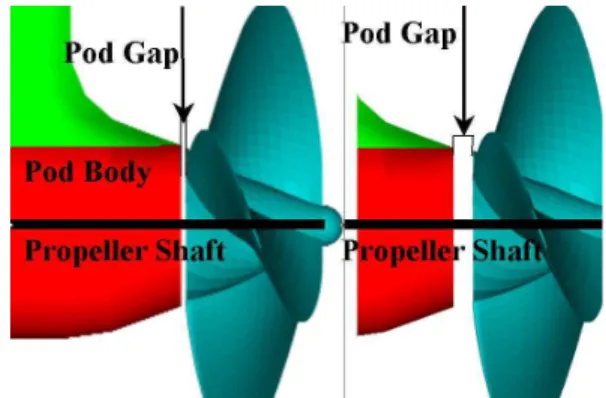
notably for large cruise ships and ferries where maneuverability at low speed is very important. Commercial application has outpaced the research knowledge on hydrodynamics of the system. One of the research issues that has been identified is the effect of pod gap on the performance of puller propulsors in straight course and azimuthing conditions, which is addressed in the present work. The pod gap distance is the axial or lateral distance between the rotating (propeller) and stationary (pod) part of a podded propulsor as shown in Figure 1.
Figure 1. Definition of pod gap distance. Mewis [2] presents results of measurements of open water characteristics of puller podded propulsors at different pod and strut gaps. In his study, the use of a special dynamometer for the open water tests highlighted the importance of the complex interaction between the pod housing and the propeller for a tractor type unit when the propeller thrust and the resistance of the pod housing were measured separately. The measurements showed that the measured propeller thrust was affected significantly by the width of the gap between the propeller hub and the pod housing. The measured unit thrust was not affected by the width of this propeller hub gap.
2 The pressure in the gap influences the measured propeller thrust. This inner force in the gap is a result of the high pressure behind the working propeller, the pressure change due to the stagnation point of the pod shaft coupled with the large gap area. The width of the gap, which can vary in different model tests, and in different towing tanks, influences the measured thrust too. The measured unit thrust is not affected by this problem because the force in the gap is an inner force of this unit. In the same study, the results of pressure measurements inside the propeller gap for different test conditions were also investigated. Based on the analysis, the author proposed to use the measured unit-thrust as the basis for the estimation of the thrust deduction fraction, effective wake fraction and propulsor efficiency [3].
Another issue addressed by Mewis was the effect of gap distance on the contemporary extrapolation methods. The adopted scale effect correction methods used in the extrapolation of the thruster propulsion test results often concentrate on the scaling of the measured “resistance” of the housing. It was argued by the author that this approach might be acceptable for the pusher type pod, but not for the tractor type due to the complex interaction between the propeller and pod housing, which results in an increased local pressure field behind the working propeller. Therefore, emphasis was placed on the gap between the pod housing and the propeller since low gap sizes would increase the resistance of the housing and the measured thrust of the propeller, if they were separately measured, although the net thrust of the pod unit would be the same. Based on this argument, it was claimed that the difference between the total thrust of the unit and the thrust of the propeller in the tractor type of unit should not be related to Reynolds number dependent viscous effects alone. Also, development of more detailed methods for the extrapolation of test results from tractor type devices was recommended [3].
As far as is known by the present authors, there has not been any numerical or experimental work reported to date which studies the effects of pod gap distance on the puller propulsor performance in azimuthing conditions. The present study focused on the effect of gap distance on the performance of propeller and unit forces and moments in straight course and azimuthing conditions.
2.
EXPERIMENTAL SET UPThe experiments included tests on a model propeller with a pod unit consisting of a combination of a pod shell and a strut. The propeller was right handed with a hub taper angle of 20° (namely, Pull-20°). The propeller was four bladed with a diameter, D of
0.27m, pitch-diameter ratio (P/D) of 1.0 and expanded area ratio (EAR) of 0.6. The geometric particulars of the propellers are given in [4].
The geometric particulars of the pod-strut model are shown in Table 1. The values for the model propulsor were selected to provide an average representation of in-service, full-scale single screw podded propulsors.
External Dimensions of Model Pods
Pod mm
Propeller Diameter, DProp 270
Pod Diameter, DPod 139
Pod Length, LPod 410
Strut Height, SHeight 300
Strut Chord Length 225
Strut Distance, SDist 100
Strut Width 60
Fore Taper Length 85
Fore Taper Angle 20°
Aft Taper Length 110
Aft Taper Angle 25°
Table 1. Geometric particulars of the pod-strut model.
The open water tests of the pod in straight course and azimuth conditions were performed in accordance with the ITTC recommended procedure, Podded Propulsor Tests and Extrapolation [5], and the description provided by Mewis [2]. A custom-designed dynamometer system [6] was used to measure propeller thrust, torque, and unit forces and moments. A short description of the instrumentation is also given in [7].
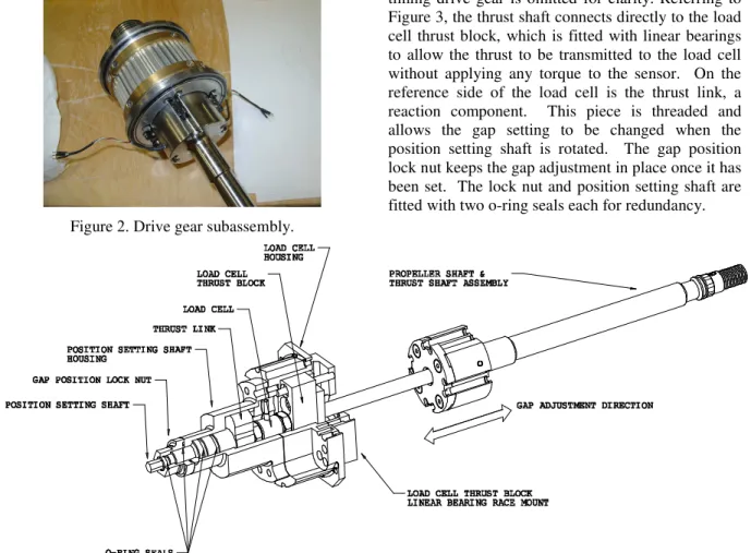
Measurement of propeller thrust with different gap distances was facilitated by designing a mechanism to quickly allow this parameter to be changed. The mechanism is composed of two subassemblies, the drive gear and gap adjustment subassemblies. These components have several functions. The drive gear subassembly displayed in Figure 2 allows the transmission of torque from the timing pulley to the propeller shaft through a set of ball bearing elements mounted in a retainer machined from plastic. These bearings also allow the smooth relative axial motion of the propeller shaft during the adjustment of the gap distance. A strain relief regime for the torque signal cables allowing torque measurement at the propeller hub location is also a feature that allows the propeller shaft to move in the axial direction. Fitted in the end of the propeller shaft is a thrust bearing, which allows the thrust force to be transmitted to the gap
adjustment mechanism and load cell via a non-rotating shaft.
Figure 2. Drive gear subassembly.
Figure 3 shows the connection between the propeller shaft and the gap adjustment mechanism. The outer timing drive gear is omitted for clarity. Referring to Figure 3, the thrust shaft connects directly to the load cell thrust block, which is fitted with linear bearings to allow the thrust to be transmitted to the load cell without applying any torque to the sensor. On the reference side of the load cell is the thrust link, a reaction component. This piece is threaded and allows the gap setting to be changed when the position setting shaft is rotated. The gap position lock nut keeps the gap adjustment in place once it has been set. The lock nut and position setting shaft are fitted with two o-ring seals each for redundancy.
Figure 3. Gap adjustment subassembly with connected propeller shaft. The operation of the mechanism is relatively simple.
First one loosens the lock nut. The position setting shaft is then rotated to move the propeller fwd or aft relative to the pod end. The gap distance is set by using feeler gauges. When the position of the propeller is set to the same thickness as the stacked feeler gauges, the lock nut is tightened and testing can resume with the new gap setting. The design range of gap settings is 0.0254 to 7.5 mm. Actual setting as assembled on the lower end is approximately 0.76 mm. Figure 4 shows two photos of the range of gap settings.
Figure 4a. Range of gap distance settings (max
gap)
Figure 4b. Range of gap distance settings (min
gap)
Part of the design was to create a point of easy access to the gap adjustment mechanism. The outer shell has a removable end that simply unscrews, allowing the experimenter to quickly change the gap setting. This detail is shown in Figure 5.
4 Figure 5 – Pod with shell end removed for
access to gap adjustment mechanism.
3.
RESULTS AND DISCUSSIONSThe pod dynamometer system was used to measure propeller and pod forces and moments, namely: propeller thrust (TProp), propeller torque (Q), unit
longitudinal force (FX) and moment (MX), unit
transverse force (FY) and moment (MY), and unit
vertical force (FZ) and moment (MZ) at the gap
distances of 0.84mm (0.3%D), 2.70mm (1.0%D) and 5.40mm (2.0%D).
For the study of gap distance, the measurements were made at the azimuthing angles from –20° to 20° with a 10° increment in puller configuration. The definition of the forces, moments and co-ordinates that were used to analyze the data and present the results are shown in Figure 6. The coordinate centre coincides with the intersection of the horizontal axis through the propeller shaft centre and the vertical axis through the strut shaft center. The results are presented in the form of traditional non-dimensional coefficients as defined in Table 2.
Figure 6. Definitions of forces, moments, co-ordinates of a puller azimuth podded propulsor.
Performance Characteristics
Data Reduction Equation
KTProp - propeller thrust
coefficient
4 2 Prop/ n D
T
ρ
KTunit - unit thrust
coefficient, KTX or Longitudinal force coefficient, KFX 4 2 Unit
/
n
D
T
ρ
or 4 2/
n
D
F
Xρ
10KQ - propeller torque coefficient 5 2/
10
Q
ρ
n
D
J - propeller advance coefficientV
A/
nD
ηProp - propeller efficiencyJ
/
2
π
×
(
K
TProp/
K
Q)
ηUnit - unit efficiencyJ
/
2
π
×
(
K
TUnit/
K
Q)
KFZ - transverse force coefficient 4 2
/
n
D
F
Yρ
KFZ - vertical force coefficient 4 2/
n
D
F
Zρ
KMX - moment coefficient around x axis 5 2/
n
D
M
Xρ
KMY - moment coefficient around y axis 5 2/
n
D
M
Yρ
KMZ - moment coefficient around z axis (steering moment) 5 2/
n
D
M
Zρ
TProp - propeller thrust ρ - water density
TUnit - unit thrust n - propeller rotational
speed
Q - propeller torque D - propeller diameter VA - propeller advance
speed, in the direction of carriage motion
F X, Y, Z - components of
the hydrodynamic force on the pod
M X, Y, Z - components of the hydrodynamic moment on the pod It should be noted that propeller advance coefficient,
J is defined using the propeller advance speed, VA in
the direction of carriage motion (in the direction of X in the inertial frame), not in the direction of propeller axis. The propeller thrust, TProp is defined in the
direction of the propeller axis, not as the projected forces on X-axis on the inertial frame.
3.1 Effect of gap distance on propeller
performance
Figures 7 to 11 show the propeller thrust and torque coefficients and efficiency curves for 0.3%D, 1.0%D and 2.0%D gap distances in the straight ahead condition and 4 different azimuthing conditions. As shown in Figure 7, the gap distance did not affect the propeller torque for any of the advance coefficient values in the straight ahead condition. However, the thrust and hence the propulsive efficiency were affected by the change in pod gap distance and the
effect increased with the increase of advance coefficients. At the azimuthing condition of 10°Port, both the propeller thrust and torque coefficients were affected by gap distance (Figure 8). The changes in torque coefficient with the change of gap distance were similar for all values of advance coefficients. However, for thrust coefficient and efficiency, the changes were more obvious at higher advance coefficients. The effect of gap distance on thrust, torque and efficiency was similar for the other azimuthing conditions (20° Port, -10° Star, -20° Star).
Propeller Performance in Straight Condition Pod 2 in Puller Configuration
0.00 0.10 0.20 0.30 0.40 0.50 0.60 0.70 0.80 0.00 0.10 0.20 0.30 0.40 0.50 0.60 0.70 0.80 0.90 1.00 1.10 1.20 Advance Coefficient., J K T , 1 0 K Q a n d E ff ic ie n c y KT_Gap0.3% KT_Gap1.0% KT_Gap2.0% 10KQ_Gap0.3% 10KQ_Gap1.0% 10KQ_Gap2.0% Eta_Gap0.3% Eta_Gap1.0% Eta_Gap2.0%
Figure 7. Propeller performance coefficients of Pod 2 in straight ahead condition.
Propeller Performance in 10° Port Azimuthing Condit ion Pod 2 in Puller Configuration
0.00 0.10 0.20 0.30 0.40 0.50 0.60 0.70 0.80 0.00 0.10 0.20 0.30 0.40 0.50 0.60 0.70 0.80 0.90 1.00 1.10 1.20 Advance Coefficient., J K T , 1 0 K Q a n d E ff ic ie n c y KT_Gap0.3% KT_Gap1.0% KT_Gap2.0% 10KQ_Gap0.3% 10KQ_Gap1.0% 10KQ_Gap2.0% Eta_Gap0.3% Eta_Gap1.0% Eta_Gap2.0%
Figure 8. Propeller performance coefficients of Pod 2 in 10° (Port side) azimuthing condition.
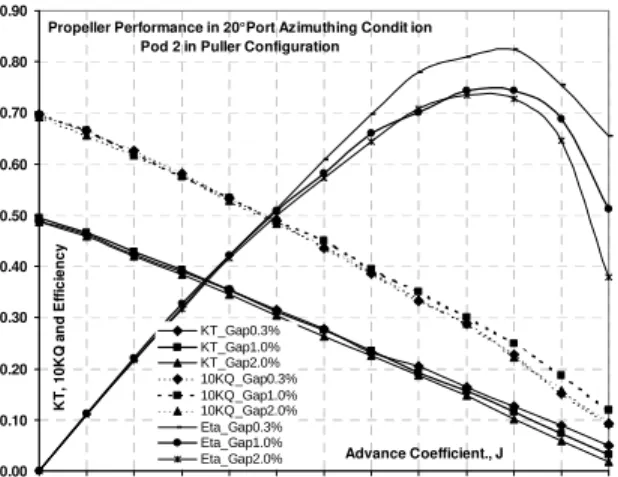
Propeller Performance in 20° Port Azimuthing Condit ion Pod 2 in Puller Configuration
0.00 0.10 0.20 0.30 0.40 0.50 0.60 0.70 0.80 0.90 0.00 0.10 0.20 0.30 0.40 0.50 0.60 0.70 0.80 0.90 1.00 1.10 1.20 Advance Coefficient., J K T , 1 0 K Q a n d E ff ic ie n c y KT_Gap0.3% KT_Gap1.0% KT_Gap2.0% 10KQ_Gap0.3% 10KQ_Gap1.0% 10KQ_Gap2.0% Eta_Gap0.3% Eta_Gap1.0% Eta_Gap2.0%
Figure 9. Propeller performance coefficients of Pod 2 in 20° (Port side) azimuthing condition.
Propeller Performance in 10° Starboard Azimuthing C ondition Pod 2 in Puller Configuration
0.00 0.10 0.20 0.30 0.40 0.50 0.60 0.70 0.80 0.00 0.10 0.20 0.30 0.40 0.50 0.60 0.70 0.80 0.90 1.00 1.10 1.20 Advance Coefficient., J K T , 1 0 K Q a n d E ff ic ie n c y KT_Gap0.3% KT_Gap1.0% KT_Gap2.0% 10KQ_Gap0.3% 10KQ_Gap1.0% 10KQ_Gap2.0% Eta_Gap0.3% Eta_Gap1.0% Eta_Gap2.0%
Figure 10. Propeller performance coefficients of the Pod 2 in -10° (starboard side) azimuthing condition.
Propeller Performance in 20° Starboard Azimuthing C ondition Pod 2 in Puller Configuration
0.00 0.10 0.20 0.30 0.40 0.50 0.60 0.70 0.80 0.90 0.00 0.10 0.20 0.30 0.40 0.50 0.60 0.70 0.80 0.90 1.00 1.10 1.20 Advance Coefficient., J K T , 1 0 K Q a n d E ff ic ie n c y KT_Gap0.3% KT_Gap1.0% KT_Gap2.0% 10KQ_Gap0.3% 10KQ_Gap1.0% 10KQ_Gap2.0% Eta_Gap0.3% Eta_Gap1.0% Eta_Gap2.0%
Figure 11. Propeller performance coefficients of the Pod 2 in -20° (starboard side) azimuthing condition. To assess the influence of the gap distance on the podded propulsor performance, the differences in performance coefficients of the pod for the 0.3%D
6 and 2.0%D gap distances compared to that of the 1.0%D gap distance are shown in Table 3. The percent values for thrust and torque coefficients were calculated using equation 1 and for efficiency were calculated using equation 2.
(
% 1%)
100/ 1% 0.0 % = − × = J gap gap gap x X X X Diff …(1)(
% 1%)
100/ 1% 0.8 % = − × = J gap gap gap x X X X Diff …(2) KTProp20Star Zero 20Port J\Gap 0.3% 2.0% 0.3% 2.0% 0.3% 2.% 0.00 1.35 -0.32 -1.08 -1.99 -1.48 -1.37 0.20 -1.22 -2.46 -2.21 -1.89 -1.16 -1.98 0.40 -1.62 -1.31 -1.30 -1.74 0.02 -1.75 0.60 -0.78 -2.08 -0.19 -1.15 0.53 -2.39 0.80 -1.69 -2.98 -0.15 -1.43 2.23 -1.34 1.00 -0.40 -3.28 0.48 -1.78 2.10 -2.91 KQ 0.00 3.20 0.51 0.21 -0.77 0.16 -0.68 0.20 0.36 -2.11 0.64 0.20 0.95 -0.53 0.40 -1.17 -1.25 0.20 -0.24 0.12 -0.71 0.60 -1.00 -2.16 -0.13 0.14 -2.13 -1.72 0.80 -1.86 -2.29 -0.69 -0.10 -2.42 -2.15 1.00 -3.01 -2.97 -0.08 -0.22 -2.91 -3.73 ηProp 0.00 0.00 0.00 0.00 0.00 0.00 0.00 0.20 -0.53 -0.13 -1.04 -0.77 -0.75 -0.53 0.40 -0.41 -0.10 -2.14 -1.35 -0.07 -0.93 0.60 1.51 -0.27 1.17 -2.12 3.64 -1.41 0.80 1.93 -2.78 3.16 -4.17 11.07 0.89 1.00 4.26 -5.65 9.09 -11.36 11.32 -2.30
Table 3. Percentage differences of propeller performance coefficients at different gap distances. From Figures 7 to 11, and Table 3, it is observed that for the podded unit in puller configurations, increasing or decreasing the gap distance had an effect on propeller thrust and efficiency in straight course operating conditions, but no effect on torque coefficients in the range of advance coefficients tested. However, in azimuthing conditions, both thrust and torque coefficients were affected by the change of gap distance especially at higher advance coefficient values. Increasing the gap distance had a decreasing effect on propeller thrust coefficient and efficiency as the advance coefficient was increased from 0.2 to 1.2. At an advance coefficient of 0.8, an increase of 3% and a decrease of 4% of efficiency occurred at a gap distance of 0.3%D and 2.0%D compared to the efficiency achieved at the gap distance of 1.0%D in straight ahead conditions. In the
20° Port azimuthing condition, the corresponding values were 11% and 1%. In the -20°Starboard azimuthing condition, the corresponding values were 2% and 3%.
3.2 Effect of Gap Distance on Unit
Performance
The plots for axial/longitudinal force coefficients, propeller torque coefficient and unit efficiency versus propeller advance coefficient are given in Figures 12 to 16 for 0.3%D, 1.0%D and 2.0%D gap distances in the straight ahead condition and 4 different azimuthing conditions. It is seen from the figures that the unit thrust and the efficiency were not affected by the change in gap distance for any values of advance coefficients when the uncertainty in the data is taken into considerations.
Propulsor Unit Performance in Straight Condition Pod 2 in Puller Configuration
0.00 0.10 0.20 0.30 0.40 0.50 0.60 0.70 0.80 0.00 0.10 0.20 0.30 0.40 0.50 0.60 0.70 0.80 0.90 1.00 1.10 1.20 Advance Coefficient., J K T , 1 0 K Q a n d E ff ic ie n c y KT_Gap0.3% KT_Gap1.0% KT_Gap2.0% 10KQ_Gap0.3% 10KQ_Gap1.0% 10KQ_Gap2.0% Eta_Gap0.3% Eta_Gap1.0% Eta_Gap2.0%
Figure 12. Unit performance coefficients of the Pod in straight ahead condition.
Unit Performance in 10° Port Azimuthing Condition Pod 2 in Puller Configuration
0.00 0.10 0.20 0.30 0.40 0.50 0.60 0.70 0.80 0.00 0.10 0.20 0.30 0.40 0.50 0.60 0.70 0.80 0.90 1.00 1.10 1.20 Advance Coefficient., J K T , 1 0 K Q a n d E ff ic ie n c y KT_Gap0.3% KT_Gap1.0% KT_Gap2.0% 10KQ_Gap0.3% 10KQ_Gap1.0% 10KQ_Gap2.0% Eta_Gap0.3% Eta_Gap1.0% Eta_Gap2.0%
Figure 13. Unit performance coefficients of the Pod in 10° (port side) azimuthing condition.
Unit Performance in 20° Port Azimuthing Condition Pod 2 in Puller Configuration
0.00 0.10 0.20 0.30 0.40 0.50 0.60 0.70 0.00 0.10 0.20 0.30 0.40 0.50 0.60 0.70 0.80 0.90 1.00 1.10 1.20 Advance Coefficient., J K T , 1 0 K Q a n d E ff ic ie n c y KT_Gap0.3% KT_Gap1.0% KT_Gap2.0% 10KQ_Gap0.3% 10KQ_Gap1.0% 10KQ_Gap2.0% Eta_Gap0.3% Eta_Gap1.0% Eta_Gap2.0%
Figure 14. Unit performance coefficients of the Pod in 20° (port side) azimuthing condition.
Unit Performance in 10° Starboard Azimuthing Condit ion Pod 2 in Puller Configuration
0.00 0.10 0.20 0.30 0.40 0.50 0.60 0.70 0.00 0.10 0.20 0.30 0.40 0.50 0.60 0.70 0.80 0.90 1.00 1.10 1.20 Advance Coefficient., J K T , 1 0 K Q a n d E ff ic ie n c y KT_Gap0.3% KT_Gap1.0% KT_Gap2.0% 10KQ_Gap0.3% 10KQ_Gap1.0% 10KQ_Gap2.0% Eta_Gap0.3% Eta_Gap1.0% Eta_Gap2.0%
Figure 15. Unit performance coefficients of the Pod in -10° (starboard side) azimuthing condition.
Unit Performance in 20° Starboard Azimuthing Condit ion Pod 2 in Puller Configuration
0.00 0.10 0.20 0.30 0.40 0.50 0.60 0.70 0.00 0.10 0.20 0.30 0.40 0.50 0.60 0.70 0.80 0.90 1.00 1.10 1.20 Advance Coefficient., J K T , 1 0 K Q a n d E ff ic ie n c y KT_Gap0.3% KT_Gap1.0% KT_Gap2.0% 10KQ_Gap0.3% 10KQ_Gap1.0% 10KQ_Gap2.0% Eta_Gap0.3% Eta_Gap1.0% Eta_Gap2.0%
Figure 16. Unit performance coefficients of the Pod in -20° (starboard side) azimuthing condition.
3-2. Effect of Gap Distance on Unit Forces and Moments
Figures 17 to 20 show the plot of the side/transverse force coefficients, the vertical force coefficients, the axial moment coefficients and the steering moment coefficients versus the advance coefficient of the propulsor for the gap distances of 0.3%D, 1.0%D and 2.0%D in the straight ahead conditions and 4 different azimuthing conditions. It can be seen from the figures that the unit force and moment coefficients were not affected by the change in gap distance both in the straight-ahead conditions and azimuthing conditions for any of the advance coefficient values. The differences in the values of the unit forces and moments (Figure 17 to 20) between the gap distances at a particular azimuth angle and advance coefficient values are attributed to the uncertainly in the test equipment ([8] and [9]). It should be noted that the data presented in the paper is from a preliminary analysis without any curve fitting or smoothing technique being applied.
Transverse/Side Force Coefficient in Straight and Azimuthing Conditions Pod 2 with 0.3% , 1% and 2% Gap in Puller Configuration
-0.80 -0.60 -0.40 -0.20 0.00 0.20 0.40 0.60 0.80 0.00 0.10 0.20 0.30 0.40 0.50 0.60 0.70 0.80 0.90 1.00 1.10 1.20 Advance Coefficient., J K F Y Straight_Gap0.3% Straight_Gap1.0% Straight_Gap2.0% 10Port_Gap0.3% 10Port_Gap1.0% 10Port_Gap2.0% 10Star_Gap0.3% 10Star_Gap1.0% 10Star_Gap2.0% 20Port_Gap0.3% 20Port_Gap1% 20Port_Gap2% 20Star_Gap0.3% 20Star_Gap1% 20Star_Gap2%
Figure 17. Side force coefficients of the Pod in different azimuthing condition.
Vertical Force Coefficient in Straight and Azimuthing Conditions Pod 2 with 0.3% , 1% and 2% Gap in Puller Configuration
-0.40 -0.30 -0.20 -0.10 0.00 0.10 0.20 0.30 0.40 0.50 0.60 0.00 0.10 0.20 0.30 0.40 0.50 0.60 0.70 0.80 0.90 1.00 1.10 1.20 Advance Coefficient., J K F Z Straight_Gap0.3% Straight_Gap1.0% Straight_Gap2.0% 10Port_Gap0.3% 10Port_Gap1.0% 10Port_Gap2.0% 10Star_Gap0.3% 10Star_Gap1.0% 10Star_Gap2.0% 20Port_Gap0.3% 20Port_Gap1% 20Port_Gap2% 20Star_Gap0.3% 20Star_Gap1% 20Star_Gap2%
Figure 18. Vertical force coefficients of the Pod in different azimuthing condition.
8
Axial Moment Coefficient in Straight and Azimuthing Conditions Pod 2 with 0.3% , 1% and 2% Gap in Puller Configuration
-0.60 -0.50 -0.40 -0.30 -0.20 -0.10 0.00 0.10 0.20 0.30 0.40 0.50 0.60 0.70 0.80 0.00 0.10 0.20 0.30 0.40 0.50 0.60 0.70 0.80 0.90 1.00 1.10 1.20 Advance Coefficient., J K M X Straight_Gap0.3% Straight_Gap1.0% Straight_Gap2.0% 10Port_Gap0.3% 10Port_Gap1.0% 10Port_Gap2.0% 10Star_Gap0.3% 10Star_Gap1.0% 10Star_Gap2.0% 20Port_Gap0.3% 20Port_Gap1% 20Port_Gap2% 20Star_Gap0.3% 20Star_Gap1% 20Star_Gap2% 0.3123
Figure 19. Axial moment coefficients of the Pod in different azimuthing condition.
Steering Moment Coefficient in Straight and Azimuthing Conditions Pod 2 with 0.3% , 1% and 2% Gap in Puller Configuration
-0.20 -0.16 -0.12 -0.08 -0.04 0.00 0.04 0.08 0.00 0.10 0.20 0.30 0.40 0.50 0.60 0.70 0.80 0.90 1.00 1.10 1.20 Advance Coefficient., J K M Z Straight_Gap0.3% Straight_Gap1.0% Straight_Gap2.0% 10Port_Gap0.3% 10Port_Gap1.0% 10Port_Gap2.0% 10Star_Gap0.3% 10Star_Gap1.0% 10Star_Gap2.0% 20Port_Gap0.3% 20Port_Gap1% 20Port_Gap2% 20Star_Gap0.3% 20Star_Gap1% 20Star_Gap2%
Figure 20. Steering moment coefficients of the Pod in different azimuthing condition.
4.
CONCLUSIONThe present set of experiments investigated the effects of gap distance on the propeller and unit performance of podded propulsors in puller configuration in the straight ahead and azimuthing conditions.
The experiments consisted of testing of a model pod unit in puller configuration at gap distances of 0.3%, 1.0% and 2.0% of propeller diameter, at straight-ahead and 10°Port, 20°Port, -10°Starboard and – 20°Starboard azimuthing conditions for the advance coefficient values of 0.0 (bollard pull condition) to 1.2. The data presented in the paper is from a preliminary analysis without any curve fitting or smoothing technique being applied.
The study showed that the gap distance did not affect the propeller torque for any of the advance coefficient values in straight-ahead condition. However, the thrust and hence the propulsive efficiency were
affected by the change in pod gap distance and the effect was increased with the increase of advance coefficients. At azimuthing conditions, both the propeller thrust and torque coefficients were affected by gap distance. The changes in torque coefficients with the change of gap distance were similar for all of the advance coefficient values. However, for propeller thrust coefficient and efficiency, the changes were more obvious at higher advance coefficients.
The unit thrust and efficiency were not affected by the change in gap distance for any values of advance coefficients in any of the azimuthing conditions. It can also be concluded that unit side and vertical force coefficients and unit axial and steering moments were not affected by the change in gap distance both in straight-ahead and azimuthing conditions for any of the advance coefficient values.
A
CKNOWLEDGEMENTSThe authors thank the Natural Sciences and Engineering Research Council (NSERC) Canada, the National Research Council (NRC), Oceanic Consulting Corp., Thordon Bearings Inc., and Memorial University for their financial and other support. Thanks are also extended to Mr. Jim Gosse and other technical service staff of Memorial University.
R
EFERENCES[1] Rains, D. A. and Vanlandingham, D. J, “Hydrodynamics of podded ship propulsion”, Journal of Hydronautics, vol. 14, no. 1-4, pp. 18-24., 1981.
[2] F. Mewis, “The efficiency of pod propulsion," in HADMAR 2001, pp. 1-12, October 2001. [3] Bose, N., Billet, M., Anderson, P., Atlar, M,
Dugue, C., Ferrando, M., and Qian, W., “The Specialist Committee on Unconventional Propulsors: Final Report and Recommendations to the 22rd ITTC”, Proceedings of the 22rd ITTC - Volume I, pp. 1-37, 2002.
[4] Liu, P., “The Design of a Podded Propeller Base Model Geometry and Prediction of its Hydrodynamics”, Technical Report no. TR-2006-16, Institute for Ocean Technology, National Research Council, Canada, 16p., 2006. [5] ITTC – Recommended Procedures, “Propulsion,
Performance - Podded Propeller Tests and Extrapolation”, 7.5-02-03-01.3, Revision 00., 2002.
[6] MacNeill, A., Taylor, R., Molloy, S., Bose, N., Veitch, B., Randell, T. and Liu, P., “Design of Model Pod Test Unit”, Proceedings of the 1st International Conference on Technological
Advances in Podded Propulsion, Newcastle University, UK, April, pp. 447-458, 2004. [7] Islam, M, Veitch, B., Akinturk, A., Bose, N., and
Liu, P., “Experiments with podded propulsor in static azimuthing conditions”, Proceedings of the 8th CMHSC, St. John’s, NL Canada, October 16-17, 8p, 2007
[8] Taylor, R. Veitch, B., and Bose, N., “Uncertainty analysis in podded propeller open water tests”, Proceedings of the 8th CMHSC, St. John’s, NL Canada, October 16-17, 8p, 2007
[9] Islam, M. F., “Uncertainty analysis of NSERC-NRC pod dynamometer system.” Ocean Engineering Research Center (OERC) Report No. OERC-2006-05, St. John’s, NL, Canada, 96p., 2006.