BBF RFC94 Type IIS Assembly for Bacterial Transcriptional Units
BBF RFC 94: Type IIS Assembly for Bacterial Transcriptional Units: A Standardized Assembly Method for Building Bacterial Transcriptional Units Using the Type IIS Restriction Enzymes
BsaI and BbsI
Team Instructors: Traci L. Haddock, Douglas M. Densmore
Graduate Student Advisors: Evan Appleton (2012-‐2014); Swati Carr (2012); Sonya Iverson (2012-‐ 2013)
2012 BostonU iGEM students: Monique De Freitas, Shawn Jin
2013 BostonU iGEM students: Jake Awtry, Devina Desai, Shawn Jin, Thomas Lozanoski, Pooja Shah 2014 BostonU iGEM students: Yash Agarwal, Kathleen Lewis, Alan Pacheco
24 July 2015
1. Purpose
This RFC94 describes an assembly standard based on the Type IIS restriction enzymes BsaI and BbsI (also called BpiI). This assembly standard is based upon the Modular Cloning (MoClo) assembly strategy, which was introduced in 2011 by Weber et al. [1] and is based upon Golden Gate cloning [2].
In this RFC, we describe our proposed MoClo standard for generating a library of bacterial DNA parts for generating four-‐part transcriptional units (promoter : 5’UTR : CDS : 3’UTR). In this work, we define 5’UTRs as including ribosomal binding sites (RBS) and bi-‐cistronic design elements (BCDs) [3], and 3’UTRs as transcriptional terminators. The 2012-‐2014 BostonU iGEM teams completed this work and a more compact library has also been created based on this work [4].
We describe an updated assembly standard based on this MoClo strategy that allows for the following features:
• Assembly scar is 4bp, which is defined by the user. While Type IIS assembly can allow for seamless integration between DNA Parts, MoClo uses a set of 4bp scars for standardizing a library of DNA parts.
• Single pot reaction for the simultaneous digestion and ligation of up to 6 DNA Parts, thus eliminating the need for gel electrophoresis and extraction currently required for BioBricks assembly (RFC10).
• By interchanging the two Type IIS restriction sites used between assembly levels, the number of assembly cycles is limited only by the choice of vector and chassis. • By only using a blue-‐white screening assay between assembly levels, there is little
confusion about which colonies to screen, which is an improvement upon the original protocol [1] which alternated between CRed and LacZ screening adding an unnecessary level of complexity.
• We have improved the efficiency of the MoClo reaction and decreased the reaction time.
2. Relation to other BBF RFCs
This RFC94 does not update or replace any earlier BBF RFCs. RFC28, RFC53, RFC61, RFC88, and RFC92 all describe the use of Type IIS restriction enzymes for the purpose of directional assemble of DNA fragments.
3. Copyright Notice
Copyright (C) The BioBricks Foundation (2015). All Rights Reserved.
4. Description
4.1 BsaI and BbsI Restriction Enzymes
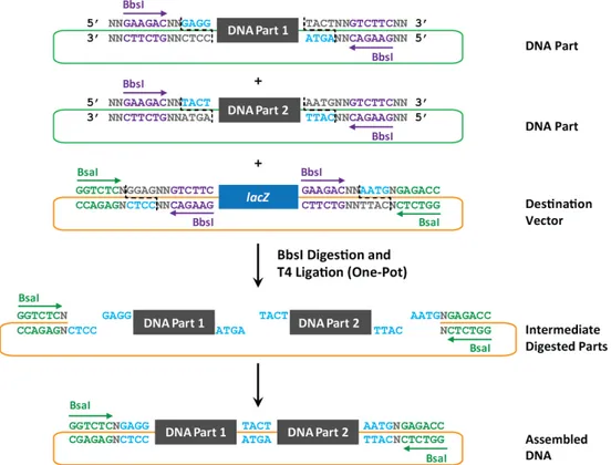
BsaI and BbsI (also called BpiI) are Type IIS restriction enzymes that have different six base pair non-‐ palindromic recognition sequences and cut at positions +1/+5 and +2/+6, respectively. A key feature for using these enzymes is the ability to remove the restriction sites from the final assembly product. When oriented properly, the restriction sites can be removed from the final product during the digestion and ligation process, thus eliminating the enzyme site scar and leaving behind a short 4bp scar in the assembled DNA (Figure 1).
Figure 1: Directional Assembly Using BbsI and BsaI. DNA Parts are shown in green backbones to denote Antibiotic Selection A, while the Destination Vector is shown in an orange backbone to denote Antibiotic Selection B. BbsI (shown in purple) recognizes 5’ GAAGAC 3’ and cuts distally at +2/+6 as shown (black dashed lines). BsaI (shown in green) recognizes 5’ GGTCTC 3’ and cuts distally at +1/+5 (not shown). These two enzymes leave a user-‐defined 4bp 5’ overhang, or fusion site (blue text). When the BbsI sites are oriented as shown here (purple arrows), this will leave the DNA Part and Destination Vector cloning site (shown with lacZ) flanked with two 4bp overhangs after the BbsI has digested the DNA (shown as Intermediate Digested Parts). The parts are then ligated together in the same reaction, yielding the final assembled DNA (shown at bottom). This allows for directional assembly and results in the removal of BbsI sites, leaving the 4bp scars behind (blue text). The DNA Parts replace the lacZ coding sequence in the Destination Vector, thus allowing for the use of blue-‐white screening along with antibiotic selection (Antibiotic B as denoted by the orange backbone).
The four base pair overhang, or fusion site, created by either enzyme is user-‐defined. These fusion sites are used to enable directional assembly of DNA Parts. By defining non-‐palindromic fusion sites that flank each DNA Part, we can ensure proper order of assembly by assigning the same fusion sites between the 3’ and 5’ ends of two DNA Parts that are meant to go next to one another (Figure 1). These fusion sites should not be repeated across more than two DNA Parts within one reaction since this will result in the DNA Parts not following the proper assembly order the user designed.
These fusion sites can also be the first and last four base pairs of the DNA Part itself to create seamless, non-‐scarred assembled DNA. This option does lessen the assemble technique’s modularity since it’s unlikely you could re-‐use the Destination Vectors that the DNA Parts are cloned into;
however, this does remain an option for seamless DNA assembly. Destination Vectors are discussed further in section 4.3.
4.2 Assembly Levels
In this RFC, MoClo exists in three levels: Level 0, Level 1, and Level 2 [1]. Level 0 refers to basic DNA Parts including promoters, 5’UTRs, coding sequences (CDS), and transcriptional terminators. Level 1 refers to concatenated Level 0 Parts into a four-‐part transcriptional unit (promoter : 5’UTR : CDS : terminator). Level 2 refers to six concatenated Level 1 Parts, usually done to create more complex genetic circuits. Given how MoClo works, it is theoretically possible to generate an infinite number of MoClo Levels but other assembly constraints (ex: the length of the DNA construct) restrict the number of levels possible in the laboratory. It is feasible to create Level 3 and Level 4 Parts, provided the other prior Levels remain somewhat smaller in size. However, here we describe and provided optimized reaction protocols for the process required to go from Level 0 through Level 2, which can be easily applied to go up to Level 3 and beyond.
Selection and Screening Markers
At each level of our MoClo standard, we use antibiotic resistance as the primary marker with blue-‐ white screening as the secondary selection marker. We take advantage of antibiotic resistance markers to ensure correct selection of our final ligated product. Here, we utilize three antibiotic markers – chloramphenicol for Level 0, kanamycin for Level 1, and ampicillin for Level 2. We chose these markers so we could utilize three standard high copy backbones commonly used in synthetic biology – pSB1C3, pSB1K3, and pSB1A2 from the Parts Registry (http://parts.igem.org/).
We have also developed a more compact version of this standard that utilizes two antibiotic markers instead of three [4]. The original version utilized pSB1C3 due to the submission requirements for the iGEM competition, where new parts need to be submitted in pSB1C3 for the competition. Both versions are highly efficient, with the two-‐antibiotic system being more streamlined as it only requires two types of media instead of three.
All of our destination vectors also contain the lacZ-‐α fragment to enable blue-‐white screening when X-‐Gal and IPTG are added to the agar plates (see Section 4.3 for more details). This is different from the original MoClo method, which utilized a combination of different color selection markers at each level[1]. By using blue-‐white screening at each level, the target colonies will always be white and thus it makes the screening easier for the user.
Level 0 Parts
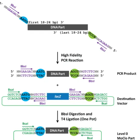
Our Level 0 Parts consist of basic DNA Parts, including promoters, 5’UTRs, CDSs, and transcriptional terminators. These basic DNA Parts are first PCR amplified to add the correct fusion sites and BbsI sites on either side of the DNA sequence (see Section 5.1 for oligonucleotide templates). The orientation of the BbsI sites is crucial, where the 3’ BbsI site is inverted while the 5’ BbsI site is not (Figure 2). Once the correct band size is confirmed, the PCR reaction is cleaned and quantified prior to setting up a MoClo reaction (details in Section 5.2) with the PCR product and the matching
Destination Vector. Matching Destination Vectors have the appropriate restriction sites in the correct orientation and matching fusion sites to allow ligation (Figure 2; further discussed in Section 4.3). The MoClo reaction is then transformed into competent E. coli cells. After a transformed clone has been confirmed, this plasmid is now called a Level 0 Part and has the following order of DNA
sequences: BsaI site-‐N-‐Fusion site 1-‐DNA Part-‐Fusion site 2-‐N-‐inverted BsaI site (as shown as Level 0 MoClo Part in Figure 2; N denotes any nucleotide base). Notice that BbsI site is removed from the final product, thus requiring the Destination Vector to contain both BbsI and BsaI flanking the fusion sites (Figure 2, Section 5.2). This process can also be streamlined through DNA synthesis, thus removing the PCR and cleanup steps.
Figure 2: Construction of a Level 0 MoClo Part. PCR primers are designed as shown in the top of the figure to include (written 5’ to 3’) 2bp (NN), then the 6bp BbsI site GAAGAC (in purple), 2bp (NN), then the 4-‐bp fusion site (black text, with blue and green colored half circles to denote the 5’ and 3’ fusion sites, respectively), followed by 18-‐24bp of the DNA part of interest. Here we show the 5’ fusion site as AATG and the 3’ fusion site as AGGT. Once amplified with high fidelity DNA polymerase, the PCR product is mixed with the Level 0 Destination Vector that has matching fusion sites (blue and green circles) in a MoClo reaction using BbsI and T4 DNA Ligase to create the final Level 0 MoClo Part shown at the bottom. Note: PCR amplification may be replaced with synthesized DNA that follows the same rules about the restriction site orientation and fusion sites.
Level 1 Parts
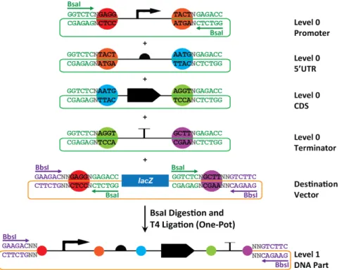
When Level 0 Parts are combined in a MoClo reaction with a Level 1 Destination Vector to form a concatenated string of Basic DNA Parts, the resulting ligation is called a Level 1 Part (Figure 3, bottom orange plasmid). In our modification of MoClo, up to four Level 0 Parts and 1 Destination Vector can be combined to create a Level 1 Part. More Level 0 Parts can be added in a Level 1 reaction [1], but our design schematic is optimized for generating 4-‐part transcriptional units. Level 1 Parts have the following order of DNA sequences: BbsI site-‐NN-‐Fusion site 1-‐DNA Part-‐Fusion site 2-‐DNA Part-‐Fusion site 3-‐DNA Part-‐Fusion site 4-‐DNA Part-‐Fusion site 5-‐NN-‐inverted BbsI site (Figure 3, orange plasmid; N denotes any nucleotide base). In Level 1 Parts, the BsaI site is removed from the final product just like BbsI site is removed in the Level 0 Parts.
Figure 3: Construction of a Level 1 MoClo Part. Four basic DNA Parts (promoter, 5’UTR, CDS, and terminator) are each shown in green vectors to denote the chloramphenicol resistance cassette and each has two 4bp non-‐palindromic fusion sites flanking the DNA Part (colored circles). The fifth vector is the Destination Vector for the final construct, which is orange to denote the kanamycin resistance cassette and contains lacZ for blue-‐white screening. The BsaI sites (green text) are shown in the DNA Part vectors and Destination Vector with the direction they cut (green arrows). The 4bp fusion sites (black text in colored circles) shown in the five top plasmids indicate the fusion sites that will remain with either the DNA Parts or the Destination Vector after the BsaI digestion. By allowing matching fusion sites between the 3’ end of the first part and the 5’ end of the second part and so on, this enables the proper assembly order of promoter-‐5’UTR-‐CDS-‐terminator to be maintained. The Destination Vector contains the fusion site on the 5’ end of the promoter and the 3’ end of the terminator to allow the properly ordered transcriptional unit to be cloned into a vector containing a different antibiotic resistance from the vectors containing the basic DNA Parts. The transcriptional unit replaces the lacZ coding sequence, thus allowing for blue-‐white screening along with antibiotic selection.
Level 2 Parts
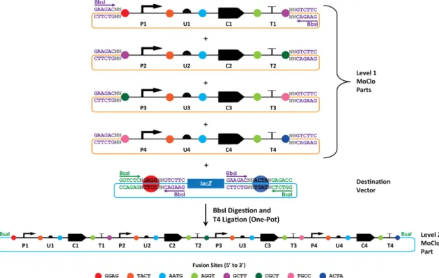
Level 2 Parts are composites composed of two or more Level 1 Parts (Figure 4). This allows users to design and implement complex functions in bacterial cells. Our system is currently optimized for concatenating up to four Level 1 Parts together into a Level 2 Destination Vector (Figure 4). During this assembly level, the BbsI restriction sites flank the Level 1 Parts on the 5’ and 3’ ends with no restriction sites within the transcriptional unit. Thus, only the first and last fusion sites in the Level 1 Parts become exposed during the restriction digest and the 3’ fusion site from the first Level 1 Part needs to match the 5’ fusion site from the second Level 1 Part (purple circles, Figure 4), and so on through the order of Level 1 Parts. In Figure 4, the 3’ fusion sites next to the terminators (T1-‐3) match the 5’ fusion sites of the promoters (P2-‐4) to ensure correct assembly order. The 5’ fusion site on P1 (red circle, Figure 4) and the 3’ fusion site on T4 (blue circle, Figure 4) match the fusion sites in the Destination Vector on the 5’ and 3’ sides of the LacZ α fragment, respectively (blue plasmid, Figure 4). In Level 2 Parts, the BbsI site is removed from the final product just like BsaI site is removed in the Level 1 Parts.
Figure 4: Construction of a Level 2 MoClo Part. Four Level 1 Parts (transcriptional units containing promoter-‐5’UTR-‐ CDS-‐terminator; labeled P1-‐U1-‐C1-‐T1 and so on) are each shown in orange vectors to denote the kanamycin resistance cassette and each has two 4bp non-‐palindromic fusion sites flanking all of the DNA Parts (colored circles). The fifth vector is the Destination Vector for the final construct, which is blue to denote the ampicillin resistance cassette and contains lacZ-‐α for blue-‐white screening. The BbsI sites (purple text) are shown in the DNA Part vectors and
Destination Vector with the direction they cut (purple arrows). By allowing matching fusion sites between the 3’ end of T1 and the 5’ end of P2 and so on, this enables the proper assembly order of the transcriptional units to be maintained. The transcriptional units replace the lacZ coding sequence, thus allowing for blue-‐white screening along with antibiotic selection.
4.3 Destination Vectors
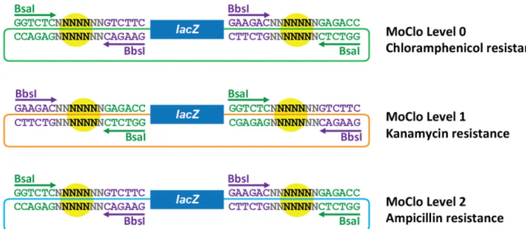
Another major component to each MoClo Level beyond the DNA Part is the Destination Vector (DV) that holds the DNA Part. These DVs contain a handful of key features that are taken advantage of during the MoClo reaction: (1) the alpha fragment of lacZ in the cloning site, (2) the lacZ fragment is flanked by either BbsI-‐fusion site-‐BsaI or BsaI-‐fusion site-‐BbsI depending on the MoClo Level, and (3) an antibiotic cassette which is specific to each MoClo Level. These three key features are further discussed below.
(1) Alpha lacZ fragment: During the MoClo reaction wherein a DNA Part is added into a DV, the lacZ cassette is knocked out of the DV and replaced with the DNA Part. This allows for blue-‐ white screening along with antibiotic selection during the transformation process. This process occurs in all MoClo Levels so X-‐Gal and IPTG are added to all plates when doing transformations following MoClo reactions. Details on our plating protocol can be found in Section 5.4.
(2) lacZ Flanking Region: In order for the DNA Part to ligate properly into the DV, the DV must contain the matching fusion sites. These sites are flanked by both BsaI and BbsI sites, although the order of those sites depends on the MoClo Level (Figure 5). When the lacZ fragment is cut out of the DV, it leaves behind the Level-‐appropriate restriction sites and the fusion sites to allow the DNA Part to ligate into the cloning site of the DV.
(3) Antibiotic Resistance: Each level has a different antibiotic resistance cassette in order to further select for the correct colonies after transformation of the MoClo reaction. In our work, Level 0 has chloramphenicol, level 1 has kanamycin, and level 2 has ampicillin resistance. Details of our antibiotic concentrations can be found in Section 5.4.
In order for MoClo reactions to work efficiently and easily, these three DV characteristics must be maintained. By using only one color screening method for all three levels, the selection of correct clones becomes easier for the user. The flanking region sequences must be carefully checked prior to use in a MoClo reaction or else the reaction efficiency will most likely be negatively impacted. The third feature of having different antibiotic selection markers for each MoClo Level allows the user to take advantage of a secondary screening step to ensure proper DVs were utilized in the reaction.
For our Level 0, Level 1 and Level 2 backbones, we have utilized pSB1C3, pSB1K3, and pSB1A2, respectively, from the Parts Registry (http://parts.igem.org/) with the lacZ-‐α fragment cloned into the SpeI restriction site of each vector. We have also removed the mRFP marker found in the BioBricks™ cloning site in the original backbones prior to cloning in our lacZ-‐α fragment.
Figure 5: Destination Vector Detail for MoClo Levels 0-2. The BsaI (in green) and BbsI (in purple) sites are interchanged between levels. The green backbone in Level 0 denotes chloramphenicol resistance, the orange for Level 1 is kanamycin, and the blue for Level 2 is ampicillin. The alpha lacZ fragment is in the cloning site for each level and the 4 black N’s within the yellow circles denote the fusion sites, to be designed by the user.
4.4 Assembly Rules
• Illegal Cut Sites: BbsI and BsaI sites are illegal cut sites for Basic DNA Parts and need to be removed in order to be used in this system.
• Selection Markers: Blue-‐white screening and antibiotic selection are required at each level to ensure proper assembly. We suggest that Level 0 uses chloramphenicol, Level 1 uses
kanamycin, and Level 2 uses ampicillin. However, two antibiotics can also be used (as shown in the smaller library based on this work [3]). Either way, we recommend that users employ at least two different antibiotic markers, with Level 0 and Level 2 Parts containing one antibiotic marker while Level 1 has the other marker. This allows users to select for a different antibiotic resistance between Levels.
• Fusion Sites: See Table 1 for suggested fusion sites for this assembly standard. All 5’UTRs are flanked by the same fusion sites (5’ TACT and 3’ AATG); likewise, all CDSs are flanked by their own fusion sites (5’ AATG and 3’ AGGT). Promoters and terminators vary in their fusion site on the 5’ and 3’ side, respectively (Table 1). Destination vectors must have matching fusion sites with their inserts. Fusion sites must vary by more than 1bp in order to maintain high assembly efficiency.
• Enzyme Usage: Level 0 and 2 MoClo reactions utilize BbsI and Level 1 MoClo reactions utilize BsaI. All reactions utilize T4 DNA Ligase and DNA Ligase buffer (details in Section 5.2).
5. Methods
5.1 DNA Parts and Destination Vector PCR
Oligonucleotide template for creating Level 0 Parts (1234 and 5678 refer to user-‐designed fusion sites):
Forward Oligo: 5’ NN BbsI NN fusion site[first 24bp of DNA part]
Generic: 5’ NNGAAGACNN1234[first 24bp of DNA part]
Our Design: 5’ ATGAAGACGT1234[first 24bp of DNA part]
Reverse Oligo*: 5’ [last 24bp of DNA part]fusion site NN BbsI NN
Generic: 5’ [last 24bp of DNA part]5678NNGTCTTCNN
Our Design: 5’ [last 24bp of DNA part]5678AGGTCTTCGT
*Reverse complement of the oligo is ordered.
Oligonucleotide template for creating Level 0 and 2 Destination Vectors (1234 and 5678 refer to user-‐designed fusion sites):
Forward Oligo: 5’ NNSpeI† N BsaI N fusion site NN BbsI[first 24bp of lacZ]
Generic: 5’ NNACTAGTNGGTCTCN1234NNGTCTTC[first 24bp of lacZ]
Our Design: 5’ TTACTAGTGGGTCTCA1234ATGTCTTC[first 24bp of lacZ]
Reverse Oligo*: 5’ [last 24bp of lacZ]BbsI NN fusion site N BsaI N SpeI† NN
Generic: 5’ [last 24bp of lacZ]GAAGACNN5678NGAGACCNACTAGTNN
Our Design: 5’ [last 24bp of lacZ]GAAGACGT5678AGAGACCTACTAGTAG
†We use SpeI in our DV oligonucleotides to facilitate cloning the lacZ alpha fragment into our backbones (pSB1C3, pSB1K3, and pSB1A2 for Levels 0, 1, and 2, respectively). Other users may need to use a different restriction site, depending on the backbones they use in their system.
*Reverse complement of the oligo is ordered.
Oligonucleotide template for creating Level 1 Destination Vectors (1234 and 5678 refer to user-‐ designed fusion sites):
Forward Oligo: 5’ NNSpeI† N BbsI NN fusion site N BsaI[first 24bp of lacZ]
Generic: 5’ NNACTAGTNGAAGACNN1234NGAGACC[first 24bp of lacZ]
Our Design: 5’ TTACTAGTGGAAGACAT1234AGAGACC[first 24bp of lacZ]
Reverse Oligo*: 5’ [last 24bp of lacZ]BsaI N fusion site NN BbsI N SpeI† NN
Generic: 5’ [last 24bp of lacZ]GGTCTCN5678NNGTCTTCNACTAGTNN
Our Design: 5’ [last 24bp of lacZ]GGTCTCT5678ATGTCTTCTACTAGTAG
†We use SpeI in our DV oligonucleotides to facilitate cloning the lacZ alpha fragment into our backbones (pSB1C3, pSB1K3, and pSB1A2 for Levels 0, 1, and 2, respectively). Other users may need to use a different restriction site, depending on the backbones they use in their system.
*Reverse complement of the oligo is ordered.
5.2 MoClo Reaction Set up
For each reaction, add the following to a PCR tube:
• 10 fmol of each DNA component with up to five components total (DNA PCR Product or previously made MoClo DNA Parts and Destination Vector)
o The DNA concentration must be equimolar for all components added, so adjust the fmol amount as needed to maintain equimolar concentrations if one component cannot reach 10 fmol
We have had success with reactions as low as 5 fmol per DNA Part • 10 U of BsaI or BbsI (BsaI for Level 1, BbsI for Level 0 and Level 2; NEB)
• 10 U T4 DNA ligase
o Promega T4 high concentration DNA ligase has a higher reaction efficiency than NEB T4 Ligase, but both do yield positive results
Promega T4 DNA ligase at 20 U/µL concentration works best (Catalog number M1794)
• 1 X T4 DNA Ligase Buffer
o Promega ligase buffer yields much higher reaction efficiencies with both brands of T4 Ligase enzyme, but NEB ligase buffer also yields positive results. It is strongly recommended that users utilize the Promega buffer.
• Sterile, deionized water added to reach a total reaction volume of 10 µL
5.3 MoClo Reaction Conditions
Program and run the thermocycler as follows: • 10-‐25 cycles: o 37°C for 1.5 minutes o 16°C for 3 minutes • 50°C for 5 minutes • 80°C for 10 minutes • 4°C hold
Recommended cycle usage • Level 0: 10 cycles • Level 1: 15-‐20 cycles • Level 2: 25 cycles
Alternative methods
• Prior to the cycling, add a step to the program to incubate tubes at 37°C for 30 minutes to increase digestion of the DNA (as seen in [3])
o This is helpful for reactions where efficiencies have been poor (< 20% white colonies)
• Lengthen the steps within the cycles to increase efficiency o 37°C for 1.5 minutes increased to 3 minutes o 16°C for 3 minutes increased to 5 minutes
This is helpful for Level 2 reactions with large (>1500 bp) Level 1 Parts
5.4 Transformation and Confirmation
Once the MoClo reaction is complete, transform 2-‐3 µL of the reaction into 10-‐25 µL of high efficiency (≥109 cfu/µg of pUC19 is best) competent Escherichia coli cells and follow the transformation
protocol associated with those cells. Spread plate 80 µL of a 20 mg/µL stock of 5-‐bromo-‐4-‐chloro-‐3-‐ indolyl ß-‐D-‐galactopyranoside (X-‐GAL) and 100 µL of a 0.1M stock of isopropyl-‐ß-‐D-‐
thiogalactopyranoside (IPTG) onto warmed LB agar plates with the appropriate antibiotic added for the MoClo level and let the plate absorb the X-‐GAL and IPTG at 37°C while the transformed cells recover. Spread plate the cells and incubate the plate inverted overnight. Select 2-‐4 white colonies per plate, set up overnight cultures in LB broth with the appropriate antibiotic added and isolate the plasmid DNA to screen the clones for the proper DNA sequence.
Antibiotics for using our Destination Vectors should be added to a final concentration of: • Level 0 -‐ Chloramphenicol: 25 µg/mL
• Level 1 -‐ Kanamycin: 35 µg/mL • Level 2 -‐ Ampicillin: 100 µg/mL
Note: Some transformation protocols do not require a recover stage (ex: Zymo Competent Cells). If this is the case, then prepare the LB agar plates prior to transforming the cells and allow them at least 30 minutes of absorption time prior to plating the cells.
5.5 Automated Protocol Generation
Our MoClo library design is also fully supported by the CIDAR lab’s software assembly tool, Raven [5] (http://ravencad.org). Users can input their basic parts and genetic device designs into Raven and obtain detailed protocol instructions for building their genetic device using this MoClo methodology. These instructions include fusion site selection, oligo designs, and a detailed MoClo protocol
description for each level of assembly.
5.6 Troubleshooting Guide
Problem Possible Reasons Solution Few white
colonies (< 20%) Incorrect fusion sites on one or more of your DNA parts
Recheck the sequence of your DNA parts. This is of particular importance for the promoter and terminators used in this RFC since all 5'UTRs and CDS Parts have the same fusion sites, respectively.
Incorrect
concentration of DNA part(s)
This may be the result of (a) incorrect initial DNA
concentration measurement (b) incorrect fmol calculation, or (c) fusion sites are too similar (within 1bp). Recheck the concentration of each part and/or recalculate the fmol dilution. Make sure you are including the full plasmid length for the fmol calculation and not just the DNA part. Make sure the fusion sites differ by more than 1bp.
Incorrect destination
vector Recheck the sequence of your destination vector.
DNA miniprep
quality is low Check the purity of your DNA preps. Residual ethanol or poorly washed minipreps will interfere with reaction efficiency.
Incorrect enzyme
usage You may have used the incorrect Type IIS restriction enzyme. If you used a master mix with your enzyme, check your other plates. If none of them have white colonies, redo the reaction. If only one plate has this problem, see the above possible reasons and solutions.
Non-‐optimal cycling
conditions
If you ran a low number of cycles (<15), re-‐do the reaction and increase the number of cycles in the MoClo reaction to 20-‐25. Cycling at 15 or less is best for making Level 0 Parts, while both Level 1 and 2 work best at 20-‐25 cycles. No colonies on
your plate
Incorrect antibiotic Check the antibiotic in your plate by streaking out cells with known constructs out on the batch of plates you used. It is best to test all antibiotics used in your library (in this RFC, we would use AmpR, KanR, and CamR constructs).
Low competency in
your competent cells Include a positive control for your competent cells when transforming to ensure your cells are highly competent. No X-‐Gal and/or
IPTG added to your plate
Make a new plate with X-‐Gal and ITPG spread plated and re-‐transform your MoClo reaction.
No blue colonies / Only white colonies with incorrect
sequence result Plated on incorrect antibiotic
You may have plated on the antibiotic that selects for the input DNA parts and not the final output part. For example, in this RFC, you may have plated a Level 1 reaction on the Level 0 antibiotic.
Incorrect concatenation of Parts
Homologous recombination
You may have used two (or more) parts with highly similar sequences. This can cause homologous recombination to occur between parts. This most often occurs at the terminator sequence in our library due to the lack of variation of terminator parts. This can also be a result of using fusion sites that differ by only 1bp.
6. Author’s Contact Information
Traci Haddock tracihaddock@gmail.com Douglas Densmore dougd@bu.edu
7. References
PLoS One, 2011. 6(2): p. e16765.
2. Engler, C., et al., Golden gate shuffling: a one-pot DNA shuffling method based on type IIs restriction enzymes. PLoS One, 2009. 4(5): p. e5553.
3. Mutalik, V. K., et al., Precise and reliable gene expression via standard transcription and translation intitiation elements. Nature Methods, 2013. 10, 354-360; doi: 10.1038/nmeth.2404
4. Iverson, S.I., et al., CIDAR MoClo: Improved DNA assembly and part library for E. coli.
Submitted to ACS Synthetic Biology, 2015.
5. Appleton, E., et al., Interactive assembly algorithms for molecular cloning. Nature Methods, 2014. 11, 657-662; doi: 10.1038/nmeth.2939
