Publisher’s version / Version de l'éditeur:
Cement and Concrete Composites, 32, 5, pp. 369-375, 2010-05-01
READ THESE TERMS AND CONDITIONS CAREFULLY BEFORE USING THIS WEBSITE.
https://nrc-publications.canada.ca/eng/copyright
Vous avez des questions? Nous pouvons vous aider. Pour communiquer directement avec un auteur, consultez la première page de la revue dans laquelle son article a été publié afin de trouver ses coordonnées. Si vous n’arrivez pas à les repérer, communiquez avec nous à PublicationsArchive-ArchivesPublications@nrc-cnrc.gc.ca.
Questions? Contact the NRC Publications Archive team at
PublicationsArchive-ArchivesPublications@nrc-cnrc.gc.ca. If you wish to email the authors directly, please see the first page of the publication for their contact information.
NRC Publications Archive
Archives des publications du CNRC
This publication could be one of several versions: author’s original, accepted manuscript or the publisher’s version. / La version de cette publication peut être l’une des suivantes : la version prépublication de l’auteur, la version acceptée du manuscrit ou la version de l’éditeur.
For the publisher’s version, please access the DOI link below./ Pour consulter la version de l’éditeur, utilisez le lien DOI ci-dessous.
https://doi.org/10.1016/j.cemconcomp.2010.02.008
Access and use of this website and the material on it are subject to the Terms and Conditions set forth at
Viscoelastic nature of calcium silicate hydrate
Alizadeh, R.; Beaudoin, J. J.; Raki, L.
https://publications-cnrc.canada.ca/fra/droits
L’accès à ce site Web et l’utilisation de son contenu sont assujettis aux conditions présentées dans le site LISEZ CES CONDITIONS ATTENTIVEMENT AVANT D’UTILISER CE SITE WEB.
NRC Publications Record / Notice d'Archives des publications de CNRC:
https://nrc-publications.canada.ca/eng/view/object/?id=6aa47b68-d94d-48f5-b878-d881cd4dabcd https://publications-cnrc.canada.ca/fra/voir/objet/?id=6aa47b68-d94d-48f5-b878-d881cd4dabcd
http://www.nrc-cnrc.gc.ca/irc
V isc oe la st ic na t ure of c a lc ium silic a t e hydra t e
N R C C - 5 2 7 1 3
A l i z a d e h , R . ; B e a u d o i n , J . J . ; R a k i , L .
M a y 2 0 1 0
A version of this document is published in / Une version de ce document se trouve dans:
Cement and Concrete Composites, 32, (5), pp. 369-375, May 01, 2010, DOI:
10.1016/j.cemconcomp.2010.02.008
The material in this document is covered by the provisions of the Copyright Act, by Canadian laws, policies, regulations and international agreements. Such provisions serve to identify the information source and, in specific instances, to prohibit reproduction of materials without written permission. For more information visit http://laws.justice.gc.ca/en/showtdm/cs/C-42
Les renseignements dans ce document sont protégés par la Loi sur le droit d'auteur, par les lois, les politiques et les règlements du Canada et des accords internationaux. Ces dispositions permettent d'identifier la source de l'information et, dans certains cas, d'interdire la copie de documents sans permission écrite. Pour obtenir de plus amples renseignements : http://lois.justice.gc.ca/fr/showtdm/cs/C-42
Viscoelastic Nature of Calcium Silicate Hydrate
Rouhollah Alizadeh*, James J. Beaudoin, Laila Raki
Institute for Research in Construction, National Research Council Canada
Abstract
The origin of the time-dependent response of cement-based materials to applied stress has not been clearly resolved. The role of interlayer water in the mechanical behavior of calcium silicate hydrate (C-S-H) is still debated. In order to better understand the pertinent mechanisms, the stress relaxation tests were conducted on thin rectangular beams of compacted synthetic C-S-H powder and hydrated Portland cement subjected to three-point bending. C-S-H specimens of variable composition (C/S=0.8, 1.2 and 1.5) were prepared at various moisture content levels from saturation to the dry state. A special drying procedure was applied in order to remove the adsorbed and interlayer water incrementally from C-S-H conditioned at 11%RH. It was shown that a significant part of the relaxation at saturation is attributed to the hydrodynamic component associated with the pore water. It was demonstrated that the viscoelastic performance of C-S-H depends considerably on the presence of interlayer water. It is argued that the results support the validity of the theory of sliding of C-S-H sheets as a time-dependent deformation mechanism responsible for the creep and stress relaxation of cement-based materials. This concept was illustrated in a proposed model for the viscoelastic response of C-S-H.
Keywords: stress relaxation, calcium silicate hydrate (C-S-H), Portland cement, time-dependent
deformations, interlayer water, viscoelastic properties
1. Introduction
The time-dependent changes in the mechanical properties of concrete have been the subject of extensive research over the past century [ 1]. In particular, the concrete creep, i.e. the strain induced under sustained loading over time, has received significant attention due to its practical implications. Although numerous studies have been conducted in this regard, the nature of creep phenomena in cement-based systems is still not clearly resolved. There are several hypotheses proposed for the concrete creep that describe possible mechanisms for the temporal deformation of hardened concrete under load [ 2, 3]. None of these theories alone can explain all the experimental observations and it appears that multiple mechanisms may be operative. It is argued that the origin of creep is situated at the micro and nano-level within the capillary space and the calcium silicate hydrate (C-S-H∗) phase, respectively, referred to as the short-term and long-term creep [ 4].
Two theories on the nature of creep that pertain to the nanostructure of the hydrated cement paste are briefly described. The microprestress-solidification theory implies that the overstressed unstable atomic-scale bonds are locally broken and reformed in the ‘hindered’ adsorbed water molecule sites (including that in the C-S-H interlayer) [ 5]. This results in a quasi-dislocation of adjacent particles through a shear slip mechanism (i.e. the sliding of C-S-H sheets [ 4]) which contributes to the long-term creep. The theory of micro-sliding between the adjacent C-S-H sheets and the change in the orientation of hydroxyl water held on the crystalline surfaces was later argued to be the main contributor to the creep behavior [ 6]. It was also shown that the
Creep of concrete has also been described in terms of a nanogranular model of C-S-H particles [ 14- 16]. It was suggested that the creep may involve the rearrangement of the C-S-H globules resulting in a tighter local packing, i.e. higher local density. This theory was later modified in Jennings’ second generation model for C-S-H (CM-II) to account for the role of large gel pores (LGP) in the creep of C-S-H [ 17]. It was suggested that the volume of LGP is gradually reduced under stress and that the LGP may collapse due to the rearrangement of particles. The interlayer water (although a feature in the CM-II) was not considered in the explanation of time-dependent deformation of C-S-H. The granular model is, nevertheless, consistent with the Feldman’s layered model for C-S-H [ 9] in that they both propose that the solid volume of C-S-H increases (i.e. tighter local packing) due to creep. It was postulated in the layered model that new interlayer regions are formed under stress [ 9, 18]. Two types of C-S-H were considered in the granular model and it was proposed that the low density (LD) C-S-H (i.e. packing density) creeps more than the high density (HD) C-S-H in cement paste possibly due to the difference in the porosity levels and not the intrinsic properties of the C-S-H [ 15]. Another category of C-S-H (ultra high density) was recently identified using a nanoindentation technique and the source of creep was attributed to the particle-to-particle contact of nano-sized C-S-H [ 19]. The moisture content of
It is well known that the stoichiometry of C-S-H in hydrated cement paste can readily be changed by various parameters such as curing conditions and use of supplementary cementitious materials [ 22]. It is therefore necessary to establish a relation between the chemistry of C-S-H and its engineering characteristics including time-dependent mechanical properties. Hardened cement paste is not an ideal material for the studies in this regard. The porosity, which has an important role in the mechanical behavior of the porous body of the solid, is obviously influenced by the mix characteristics of the cement paste. Moreover, the chemical properties of C-S-H and additional phases formed in the hydration reactions cannot be easily controlled. The mechanical characterization results therefore cannot be related independently to the stoichiometry of the C-S-H in these systems.
The stress relaxation of cement and concrete, a mechanical property that is closely related to the creep, has rarely been studied mainly due to the experimental limitations [ 23]. A relatively quick method using three-point bending of thin cement paste beams that was primarily adopted to
The synthetic semi-crystalline C-S-H (i.e. C-S-H(I) of variable C/S ratio) was chosen for this study since it has been considered as an appropriate model for the nearly amorphous C-S-H produced in the hydration of Portland cement [ 10, 30]. A solid body of the phase pure C-S-H is, however, required for the investigation of its mechanical performance. The current research utilizes the compaction technique in order to prepare rectangular beams from the powdered materials (synthetic C-S-H of variable stoichiometry) at a controlled porosity level. It should be noted that the synthetic C-S-H is a fully hydrated material and the effect of the hydration of cement during the conventional creep measurements as well as other aging mechanisms [ 31] are eliminated. The results of the stress relaxation measurement in the compacted C-S-H specimens subjected to a constant strain in a three-point bending set-up at various humidity levels are reported. Samples of hydrated Portland cement and porous glass were also tested for comparison.
2. Method
2.1. Materials
C-S-H was synthesized by means of a pozzolanic reaction between amorphous SiO2 and CaO in
excess water (water/solid ratio by mass≈10). Reactive silica (Cab-O-Sil grade M-5, Cabot Corporation) was heated at 110 °C. Calcium oxide was obtained from the calcinations of the reagent grade calcium carbonate (Sigma-Aldrich Company) at 900 °C. All materials were kept in sealed N2 purged bottles until used. Various C-S-H systems were prepared using stoichiometric
amounts of CaO and SiO2 resulting in C/S ratios of 0.8, 1.2 and 1.5. Distilled de-aired water was
then added to the dry mixture of the materials in 1L HDPE bottles. The bottles were mounted on a rotating rack (at the speed of 16 rpm) and the reaction continued for 180 days. The chemical reaction is nearly completed in the first week, but further time is required in order to obtain a well-ordered crystalline structure. The material produced was filtered after this period and dried under vacuum for 4 days at room temperature. High drying temperatures were avoided during the material preparation since the crystal structure of C-S-H can be altered in extreme drying condition occurring at temperatures above 50 °C [ 32]. The dried C-S-H powders were stored in nitrogen purged glass vials before experiments. During these steps maximum care was taken to minimize the C-S-H surface carbonation due to the exposure of the material to the CO2 in
Two other sets of samples were prepared for comparison: the cement paste and porous glass. Rectangular prisms (250x100x12 mm) were cast from the Portland cement paste (Lafarge Canada type I) at a water/cement ratio of 0.4. The prism was vibrated and stored in a moist curing room for 24 hours. It was then demoulded and curing was continued for 2 months in the saturated lime solution. Thin slices (~1x12x60 mm) were cut from the cement paste bar using an Isomet diamond saw. Vycor® porous glass plate (thickness=1.3 mm, surface area=110 cm2/g, porosity≈ 28%) was cut to give rectangular specimens measuring 12x60 mm. The length of the specimens was chosen according to the standard requirements of the three point bending test [ 33, 34]. An over-edge of about 10% of the specimen length was considered on each side from the supports. The length/thickness ratio (about 40) was well above the specified value of 8.
The C-S-H preparations and cement paste slices were conditioned for three weeks in a vacuum desiccator over the vapor pressure of a saturated lithium chloride solution. This provides a relative humidity of about 11% at room temperature which is a desirable base for studying the stoichiometry of C-S-H [ 35]. There is, theoretically, only a monolayer of adsorbed water on the surface of particles at this specific humidity in addition to the interlayer water. This state was used as the starting condition for most of the experiments in the current work. Additional samples were conditioned over the vapor pressure of water for stress relaxation experiments in the saturated state (100%RH).
Unlike the hardened cement paste that can be cast and cut into various shapes for engineering investigations, it is necessary to prepare solid samples by compacting the fine powder for mechanical measurements of phase pure materials such as calcium hydroxide and synthetic
Compacted specimens were prepared from the C-S-H powder conditioned at 11%RH for one month as follows. Two grams of C-S-H powder were compacted in a steel mould consisting of a cylinder and two closely fitting pistons. The plan view of the prepared samples is shown in Figure 1. The steel mould was first mounted vertically with the bottom piston. The C-S-H powder was then placed in the cylinder. The top piston was then placed in the cylinder and the assembly was mounted in a compression machine. The pressure was increased gradually to a specified value where it was maintained for about 30 seconds before releasing. The compacted specimen was removed by pressing out the pistons. A specific compaction pressure was applied for each C/S ratio in order to achieve a porosity level of about 30% in the compacted samples where a sufficiently large fraction of the solid material would come into the play and the
behavior would better represent that of the C-S-H. More details about the compaction procedure can be found elsewhere [ 10]. A length of 55.9 mm was cut from the rectangular compact bars to fit the specimen requirements in the stress relaxation instrument. The thickness of the compacted C-S-H samples varied between 0.8 and 1.2 mm depending on the C/S ratio and the compaction pressure. The relatively low thickness allows for decreasing the time to achieve the equilibrium state at various humidity levels and avoiding major moisture gradients that may result in micro-cracking in the test specimens subjected to drying. The compacted samples were kept in a vacuum desiccator at 11%RH. The additional conditioning at this humidity resulted in about 1% mass loss in the samples. It is suggested that the monolayer of water present on the surface of
2.2. Experimental procedure
The starting humidity condition for the compacted C-S-H specimens as previously mentioned was obtained in equilibrium with 11%RH. Saturated samples were prepared by conditioning the compacted specimens at 100%RH. Lower humidity levels were achieved by the removal of water from 11%RH conditioned samples through the application of a combination of vacuum and heat. The initial drying increments were conducted at room temperature using only vacuum in a special glass cell. The temperature was gradually increased using the voltage adjustment (with a VARIAC W5MT3) on the heating mantle wrapped around the glass cell for higher mass loss levels in the samples. The temperature inside the cell under vacuum had been previously calibrated for the voltage. In order to minimize altering the C-S-H structure, the drying temperature for most increments of mass loss was kept below 50 °C while increasing the duration of vacuum. The drying temperature never exceeded 110 °C at mass loss increments (up to 10%) approaching the dry state. These humidity levels can be considered as quasi-equilibrium states considering the substantial amount of time spent on the water removal at each increment. It takes about one to two weeks to collect the whole set of data for each sample. It is important to increase the temperature and vacuum duration between various mass loss increments very gradually in order to avoid moisture gradients that may cause micro-cracking in the specimens.
The stress relaxation test was conducted at each increment of water removal using a Rheometrics RSA III instrument. The rectangular samples were wrapped with cellophane film after drying in order to keep the humidity level constant during the test. The elasticity of cellophane wrap was negligible in comparison with that for the samples. This was examined using a steel plate with and without cellophane wrap. Moreover, there was no mass change in the specimens covered with the cellophane film during the relaxation test. The three-point bending method was used for the stress relaxation studies. A static load of 10g followed by a maximum strain of 0.02% was applied at the middle span of the samples. This sufficiently low strain level resulted in an applied stress below 2 MPa and did not cause any microcracking as verified through microscopic analysis. The load required to keep the strain constant was monitored up to four hours. The change in the corresponding stress was recorded by the computer. It should be mentioned that no indentation was observed on the surface of the samples caused by the supports since the contact line is wide enough on the flat specimens to distribute the load. Therefore, no correction was required in the deflection of the rectangular samples. The Hertizian indentation, however, has previously been observed in cement rods [ 24]. A circular cross-section essentially provides a point contact with the support and high localized stress results in measurable indentation. A separate sample was prepared and tested for each humidity level and drying state, as the stress relaxation is only partially recoverable and the sample cannot be reused for the experiments in the other humidity levels. Several C-S-H samples were tested for the same humidity level in order to obtain reliable data when certainty was not clear.
3. Results and Discussion
The results for the stress values (σt) versus time were normalized to the initial stress (σ0)
recorded after the application of the strain. The applied strain increased gradually from zero and reached the maximum constant value after about 0.1 second, at which time the maximum stress value was obtained. The data for up to about 0.6 second is relatively noisy. This shows the equilibrium state of loading is not instant and there are some parameters affecting this period before achieving a more stable state of stress. The general trend during this period, however, follows that of the later times. Some fluctuations were observed in the stress relaxation of a few samples which might be due to the experimental limitations associated with the instrument.
3.1 Porous Glass
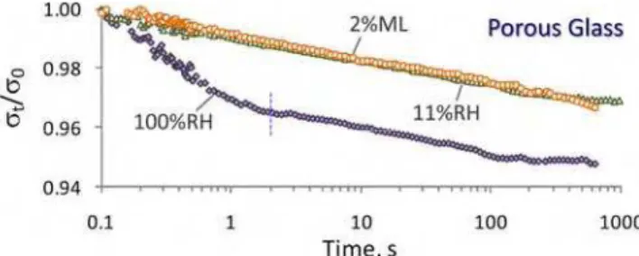
Porous Vycor® glass has been extensively used as a model system in the study of the cement-based materials [ 40].The stress relaxation curves for the porous glass samples conditioned at 11 and 100% RH are shown in Figure 2. A dry sample was also prepared from the 11%RH conditioned porous glass by applying vacuum at 110 °C for 3 hours. This resulted in about a 2% mass loss. The total stress relaxation of porous glass samples is not large. The curves show, as expected, a decrease in the stress required in order to maintain the constant strain. The rate and the extent of this decrease are dependent on the moisture content of the specimen. The maximum relaxation of about 5% is observed in the saturated specimen after about 103 s. The stress relaxation curve at this humidity level consists of two parts separated by an inflection point at about 2 seconds (indicated by a dashed vertical line on the curve). This observation is consistent
There is ideally only a monolayer of water present on the surface of the solid body of the porous glass at the 11%RH condition [ 34]. The porous glass sample at this relative humidity, therefore, does not exhibit hydrodynamic relaxation associated with the pore water and it only shows a gradual decrease in the stress at a constant rate (in log scale). The dry specimen (2% mass loss from 11%RH) demonstrates a very similar relaxation behavior to that of the 11%RH conditioned sample. It is also noted that the rate of decrease in the stress after the inflection point for the saturated sample is similar to that for the specimens at the 11%RH and dry conditions. It appears that the viscoelastic response of porous glass is not dependent on its moisture content. These observations were repeatedly made and may suggest that the monolayer of water does not have a major contribution to the stress relaxation of porous glass. It is also possible that the effect is so small that it can not be captured accurately by the current experimental setup. The latter seems more plausible as it has been suggested that the water molecules (available at 11%RH) attack the strained siloxane bonds of porous glass resulting in the viscoelastic relaxation [ 41].
3.2 C-S-H
The stress relaxation curves of compacted samples of synthetic C-S-H (C/S ratios=0.8, 1.2 and 1.5) at various humidity levels are shown in Figure 3. In all samples, the saturated specimen (100%RH) experiences a significantly higher total stress relaxation at the initial times. The shape
of the curve and the rate of decrease in the stress are different at this moisture content from those at 11%RH and below. This difference is mainly attributed to the presence of hydrodynamic component of the stress relaxation that is active at initial times in the saturated samples. This part is eliminated following the release of the pore water pressure after about 20 seconds at which time an inflection occurs in the stress relaxation curve in all the saturated C-S-H samples. The observation of the similar time for the end of hydrodynamic relaxation suggests that the C-S-H specimens have a comparable pore structure. The higher stress relaxation in the saturated samples may also be due to a contribution to shear deformation in the C-S-H structure resulting from local fluctuations in the deviatoric stress induced by pore water pressure. As mentioned, all specimens had a similar total porosity of about 30%. The remainder of the relaxation behavior is attributed to the viscoelastic component of the C-S-H phase (i.e. associated with the deformation of the solid body of the specimens).
The other curves (at 11%RH and lower moisture contents) for all C-S-H samples show a different relaxation response than that of the 100%RH condition. The hydrodynamic component, that results in a remarkable alleviation of the stress at the initial times for the saturated samples, appears to be eliminated in these specimens. This is due to the absence of ‘pore water’ at such low humidity levels. The deformation of the pore structure under stress does not lead to an increase in the pore water pressure as in the saturated condition. The stress is directly transferred to the solid structure of the compacted C-S-H agglomorates. A dominant viscoelastic response is therefore observed in all the ‘dry’ specimens from the beginning as soon as the stress is applied. It is however likely that water may exist in entrapped spaces. The water at these structural locations can not be readily removed and may slightly contribute to a negligible hydrodynamic
relaxation that would be dissipated at a prolonged period of time compared to that for the pore water. Some of the relaxation curves in the ‘dry’ state (11%RH and below) contain a subtle concave-up portion at the beginning within the first 100s. This is likely associated with a hydrodynamic component other than that related to the pore water.
It is noted (in Figure 3) that the drying of specimens conditioned at 11%RH changes the viscoelastic response of the C-S-H generally resulting in a lower stress relaxation at initial times more noticeably in the C/S=1.2 and 1.5 samples. At later times the relaxation curves may intercept with each other resulting in different total stress relaxation values not fully correlated with the mass loss level. The water molecules removed through drying of the 11%RH equilibrated samples are essentially located between the sheets of the layered synthetic C-S-H. It is, therefore, suggested that the interlayer water has a considerable role in the time-dependent viscoelastic deformation of the C-S-H. In order to examine this, a few 11%RH conditioned compacted C-S-H samples were completely dried and equilibrated again to the 11%RH condition. The first drying results in the removal of the interlayer water but water molecules cannot fully enter the interlayer region on the re-wetting at 11%RH [ 42]. The stress relaxation of the C-S-H specimens subjected to this regime (not shown) was significantly lower than that in the control specimens (originally conditioned at 11%RH). It is suggested accordingly that the presence of the interlayer water facilitates the time-dependant deformation of C-S-H under load. The mechanism of viscoelastic behavior of C-S-H may therefore be attributable to the sliding of the C-S-H sheets as hypothesized before [ 4, 6]. In order to verify this, X-ray diffraction was conducted before and after the stress relaxation test on representative C-S-H samples at various moisture content levels. Synthetic C-S-H has a basal spacing reflection (d002) unlike the C-S-H in
It has been previously shown that the mechanical properties of C-S-H systems are significantly influenced by the interlayer water [ 10]. It was also suggested that the removal of water molecules from the interlayer region may also lead to nanostructural changes primarily related to the silicate tetrahedra and the calcium ions situated between the C-S-H sheets. These changes modify the mechanical response of C-S-H at various steps resulting in an oscillatory dynamic mechanical behavior. This might be responsible for some of the inconsistencies in the order of the stress relaxation curves versus mass loss on drying of C-S-H below 11%RH. It is also noticed that the stress relaxation of the C-S-H samples having the lowest C/S ratio (C/S=0.8) does not vary substantially as the interlayer water is removed. It appears that for this C/S ratio all the curves corresponding to the moisture contents below 11%RH are qualitatively similar. At higher C/S ratios (1.2 and 1.5), however, the stress relaxation curves are well-separated for various increments of drying. This may suggest that interlayer water has a more significant structural role in high C/S ratio C-S-H. The difference in the mechanical properties of C-S-H samples separated at a C/S ratio of about 1.1 has been previously observed [ 10].
In order to compare the viscoelastic behavior of C-S-H of variable compositions together and also between the ‘dry’ states and the saturated condition, it is necessary to separate the hydrodynamic and viscoelastic components of the stress relaxation curve for samples at 100%RH. Extensive work by Scherer’s group at Princeton has led to developing and solving the stress relaxation equations for the hydrated Portland cement [ 23- 26]. These equations are applicable only at the saturated state. An analytical solution for the load (W, which is directly related to the stress) as a function of time for a rectangular cross section beam can be expressed as: ) ( ) ( ) 0 ( ) (t W Rt t W = ΨVE (1)
where R(t) is the hydrodynamic and ΨVE(t) is the viscoelastic relaxation function. The
hydrodynamic component can be described by the following equation:
) ( ) ( 1 ) (t A AS1 θ S2 κθ R = − + (2)
where A is the material parameter, S1 and S2 are functions reflecting the rate of the
hydrodynamic relaxation, θ is the reduced time (θ = t/τR) and κ is the square of the aspect ratio (κ
= a2/b2, for a sample with thickness 2a and width 2b). The S functions that are roots of the Bessel function are given approximately by:
⎥ ⎦ ⎤ ⎢ ⎣ ⎡ ⎟⎟ ⎠ ⎞ ⎜⎜ ⎝ ⎛ − − ⎟ ⎠ ⎞ ⎜ ⎝ ⎛ − ≈ ⎥ ⎦ ⎤ ⎢ ⎣ ⎡ ⎟⎟ ⎠ ⎞ ⎜⎜ ⎝ ⎛ − − ⎟ ⎠ ⎞ ⎜ ⎝ ⎛ − ≈ 670 . 0 094 . 2 5 . 0 2 551 . 0 5 . 2 5 . 0 1 1 2 exp ) ( 1 6 exp ) ( θ θ θ π θ θ θ θ π θ S S (3)
⎥ ⎥ ⎦ ⎤ ⎢ ⎢ ⎣ ⎡ ⎟⎟ ⎠ ⎞ ⎜⎜ ⎝ ⎛ − + ⎥ ⎥ ⎦ ⎤ ⎢ ⎢ ⎣ ⎡ ⎟⎟ ⎠ ⎞ ⎜⎜ ⎝ ⎛ − − ⎥ ⎥ ⎦ ⎤ ⎢ ⎢ ⎣ ⎡ ⎟⎟ ⎠ ⎞ ⎜⎜ ⎝ ⎛ − = Ψ 2 1 2 2 1 2 exp exp 1 exp ) ( b b b VE t t t t τ τ τ (4)
where τ1 and τ2 are viscoelastic relaxation times. Through the curve fitting of the equation 1 to
the experimental data of the load (or stress) versus time, the free parameters are obtained. These include theoretical load at zero time (W(0)), material property (A), hydrodynamic relaxation time (τR), viscoelastic relaxation times (τ1 and τ2) and their powers (b1 and b2). The two components
of the stress relaxation can then be easily separated. As mentioned, the data for the stress (σ(t) can be used in which case the free parameter of σ(0) is used instead of W(0).
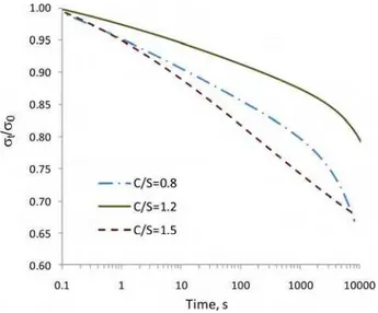
The extracted viscoelastic component of the C-S-H samples conditioned at 100%RH is shown in Figure 4. It is observed that the total viscoelastic relaxation of the saturated specimen (σ(t)/σ (0) at 104 s), for the same C/S ratio, is less than the total stress relaxation of most of the specimens dried below 11%RH. This could also be concluded indirectly from the unprocessed stress relaxation results (Figure 3) where the stress relaxation curve of the 100%RH conditioned specimen is intercepted by almost all the other curves for samples having lower moisture contents. This may suggest that the removal of interlayer water modifies the viscoelastic nature of the C-S-H and results in an increase of the total stress relaxation. The increase in the creep compliance (analogous to the stress relaxation) upon drying has been previously reported for the Portland cement paste [ 6]. It should also be noted that the 100%RH curve for porous glass (Fig. 2) does not intercept with the curves for samples at 11%RH and dried conditions. The
3.3 Hydrated Portland Cement
The stress relaxation curves of the Portland cement paste (w/c=0.4) are shown in Figure 5. The general trend in terms of the order of the curves for the samples in the saturated state to the 11%RH condition and below seems to be similar to those for the synthetic C-S-H. The saturated cement paste exhibits a distinct behavior, as mentioned for the compacted C-S-H samples, due to the hydrodynamic component of the stress relaxation. The inflection point in the curve seems to occur at about 20 seconds, analogous to that for the synthetic C-S-H, but much earlier than the values previously reported for the stress relaxation of the cement paste [ 23- 26]. This difference is possibly due the fact that the hydrodynamic relaxation time is directly related to the square of the thickness [ 26]. The average thickness of the rectangular cement paste specimens tested in the
It is noted that there is a considerable stress relaxation in the dry cement paste (Fig. 5) and C-S-H samples (Fig. 3) after the removal of final increments of water (about 10% mass loss from the 11%RH condition achieved by 24 hour vacuum drying at 110 °C). This may imply that even the completely dry solid structure of the C-S-H undergoes time-dependent deformations under load. Although water has a significant contribution to the stress relaxation of the C-S-H, it appears that the stress relaxation does occur in the dry state. This is contradictory to some research that suggests there is no creep behavior in the cement paste if the evaporable water is removed [ 13].
4. A model suggested for stress relaxation and creep
The stress relaxation of C-S-H samples consists of hydrodynamic and viscoelastic components. The hydrodynamic component depends on the pore structure characteristics of the sample and the saturation level of the pores. The viscoelastic component of the stress relaxation appears to be dependent on the nanostructural features of the C-S-H. Interlayer water is suggested to contribute significantly to the viscoelasticity of the C-S-H and thus its time-dependent mechanical properties such as stress relaxation and creep. Several models have been proposed for the creep of concrete [ 2, 3]. A combination of mechanisms appear to account for the temporal deformation of cement-based materials. The following model is proposed based on the ideas advanced in the current study with a focus on the role of interlayer water.
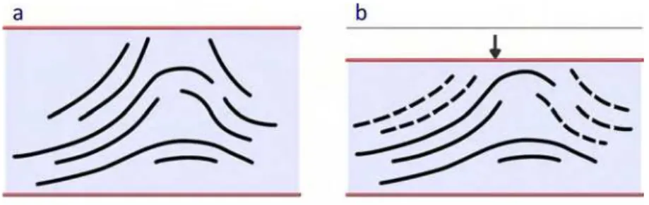
The schematic in Figure 6-a presents a very simplified model of the C-S-H. The agglomerates of layered C-S-H are formed from the stacking of several sheets of C-S-H having nanostructural
5. Concluding Remarks
The stress relaxation behavior of phase pure C-S-H (C/S=0.8, 1.2 and 1.5), hydrated Portland cement and porous glass was studied using a three-point bending method. The samples were tested at various moisture contents obtained by conditioning at 100%RH and 11%RH as well as removing water in several drying increments from the 11%RH condition.
It was shown that the hydrodynamic component (present in the 100%RH condition) has a significant contribution to the stress relaxation of C-S-H at the initial times (up to 20s). At later times when the pore water pressure is alleviated, the viscoelastic part of the stress relaxation becomes dominant. The stress relaxation curves of the samples at 11%RH and lower humidity levels apparently do not exhibit a hydrodynamic relaxation. They exhibit primarily viscoelastic behavior. The viscoelastic component of porous glass is similar at all humidity levels and does not appear to be dependent on the moisture content. In cement-based systems, however, the viscoelastic response of C-S-H is altered (generally in the form of a relative decrease at the initial times and an increase at later times) as the water is removed from the interlayer region. The total stress relaxation of most ‘dry’ specimens (i.e. conditioned at 11%RH and below) is greater than that for the samples conditioned at 100%RH in both C-S-H and cement paste shown in Figures 3 and 5, respectively. This is not the case for porous glass. It is suggested that the interlayer water plays an important role in the time-dependent deformation of cement-based materials. The viscoelastic behavior of C-S-H is attributed to the sliding of the C-S-H sheets which results in the deformation of C-S-H agglomerates under stress. The siloxane bonds may be broken and reformed due to the translation of the C-S-H layers. Removal of water from interlayer spaces
modifies the viscoelastic behavior of C-S-H resulting in a higher total stress relaxation compared to that for the saturated conditions. Understanding the details of the sliding mechanism of C-S-H layers possibly taking into account the interaction of silicate tetrahedra and cations in the interlayer region at various moisture contents should benefit from further study utilizing methods such as NMR. An investigation of the irreversible creep and stress relaxation in synthetic layered C-S-H systems at various moisture contents would provide additional insight into the nanostructural aspects of the time-dependent deformations in cement-based materials.
Acknowledgement
The authors would like to acknowledge the helpful discussions with Professor George W. Scherer at Princeton University and the financial support through an NSERC discovery grant.
References
1. Hatt W. K. “Notes on the effect of time element in loading reinforced concrete beams,”
Proceedings, American Society for Testing and Materials, 7, 421-433, 1907.
2. Neville A.M., Creep of Concrete: Plain, Reinforced, and Prestressed, North-Holland Publishing Company, Amsterdam, pp. 622, 1970.
3. Neville A.M., Dilger W., Brooks J.J., Creep of Plain and Structural Concrete, Construction Press, Longman Group, London, pp. 361, 1983.
4. Ulm F.-J., Le Maou F., Boulay C. “Creep and shrinkage coupling: New review of some evidence,” Revue Française de Génie Civil, 3, 21-37, 1999.
5. Bažant Z.P., Hauggaard A.B., Baweja S., Ulm F.-J. “Microprestress-solidification theory for concrete creep. I: aging and drying effects,” Journal of Engineering Mechanics, 123 (11) 1188-94, 1997.
6. Tamtsia B.T., Beaudoin J.J. “Basic creep of hardened cement paste – A re-examination of the role of water,” Cement and Concrete Research, 30, 1465-75, 2000.
7. Tamtsia B.T., Beaudoin J.J. “Effect of solvent exchange on length change and creep of D-dried hydrated C3S paste,” Advances in Cement Research, 13 (1) 1-9, 2001.
8. Feldman R.F. “Factors affecting the Young's modulus - porosity relation of hydrated Portland cement compacts,” Cement and Concrete Research, 2(4) 375-386, 1972. 9. Feldman R.F. “Mechanism of creep of hydrated Portland cement paste,” Cement and
Concrete Research, 2, 521-540, 1972.
10. Alizadeh R., Beaudoin J.J., Raki L. “Mechanical properties of calcium silicate hydrates,” submitted to Materials and Structures, pp.1-42, 2009.
11. Glucklich J., Ishai O. “Creep mechanism in cement mortar,” Journal of the American
Concrete Institute, 59(7) 923-948, 1962.
12. W.G. Mullen and W.L. Dolch. “Creep of Portland Cement Paste,” Proceeding of the
American Society of Testing Materials, 64, 1146-1171, 1964.
13. Brown N.H., Hope B.B., “The creep of hydrated cement paste,” Cement and Concrete
Research, 6(4) 475-486, 1976.
14. Thomas J.J., Jennings H.M. “Chemical aging and the colloidal structure of the C-S-H gel: Implications for creep and shrinkage,” Proc. 6th
Int. Conf. on Creep, Shrinkage and
Durability Mechanics of Concrete and Other Quasi-Brittle Materials (Cambridge, MA, Eds.
Ulm F.-J. et al.) Elsevier, 33-38, 2001.
15. Jennings H.M., Thomas J.J., Gevrenov J.S., Constantinides G., Ulm F.-J. “Nanostructure of C-S-H gel in cement paste as a function of curing conditions and relative humidity,” Proc. 7th
Int. Conf. on Creep, Shrinkage and Durability of Concrete and Concrete Structures (Nantes,
France, Eds. Pijaudier-Cabot G. et al.) Hermes Science, 19-37, 2005.
16. Jennings H.M., Thomas J.J., Vlahinić I. “Can nano-models lead to improved concrete? Materials science as the intersection of chemistry and mechanics,” Proc. 8th
Int. Conf. on Creep, Shrinkage and Durability of Concrete and Concrete Structures (Ise-Shima, Japan,
Eds. Tanabe T. et al.) CRC Press, 11-23, 2008.
17. Jennings H.M. “Refinements to colloid model of C-S-H in cement: CM-II,” Cement and
Concrete Research, 38, 275-289, 2008.
18. Feldman R.F., Beaudoin J.J. “Effect of applied stress on the helium inflow characteristics of hydrated Portland cement,” Cement and Concrete Research, 13, 470-476, 1983.
19. Vandamme M., Ulm F.-J. “Nanogranular origin of concrete creep,” Proceedings of the National Academy of Sciences, 106, 10552-10-557, 2009.
20. Vandamme M. “The nanogranular origin of concrete creep : a nanoindentation investigation of microstructure and fundamental properties of calcium-silicate-hydrates,” PhD thesis, Massachusetts Institute of Technology, Dept. of Civil and Environmental Engineering, http://hdl.handle.net/1721.1/43906, pp. 366, 2008.
21. Pichler Ch., Lackner R. “Identification of logarithmic-type creep of calcium-silicate-hydrates by means of nanoindenation,” Strain, 45, 17-25, 2009.
22. Taylor H. F. W., Cement Chemistry, 2nd edition, Thomas Telford Publishing, pp. 459, 1997. 23. Hansen T.C. “Estimating stress relaxation from creep data,” Materials Research and
Standards, 4 (1) 12-14, 1964.
24. Vichit-Vadakan W., Scherer G.W. “Beam-bending method for permeability and creep characterization of cement paste and mortar,” Proc. 6th
Int. Conf. on Creep, Shrinkage and Durability Mechanics of Concrete and Other Quasi-Brittle Materials (Cambridge, MA, Eds.
Ulm F.-J. et al.) Elsevier, 27-32, 2001.
25. Vichit-Vadakan W., Scherer G.W. “Measuring Permeability of Rigid Materials by a Beam-Bending Method: III, Cement Paste,” Journal of the American Ceramic Society, 85 (6) 1537-44, 2002.
26. Vichit-Vadakan W., Scherer G.W. “Measuring permeability and stress relaxation of young cement paste by beam bending,” Cement and Concrete Research, 33, 1925-32, 2003. 27. Valenza II J., Scherer G.W. “Measuring permeability of rigid materials by beam-bending
method: V, Isotropic rectangular plates of cement paste,” Journal of the American Ceramic
28. Sellevold E.J., Richards C.W. “Short-time creep transition for hardened cement paste,”
Journal of the American Ceramic Society, 55 (6) 284-289, 1972.
29. Beaudoin J.J., Tamtsia B.T. “Early age strain recovery of hardened cement paste – microstructural factors,” Advances in Cement Research, 15 (2) 51-56, 2003.
30. Alizadeh R., Beaudoin J. J., Raki L., “C-S-H (I) – A Nanostructural Model for the Removal of Water from Hydrated Cement Paste?,” Journal of the American Ceramic Society, 90 (2) 670-672, 2007.
31. Grasley Z.C., Lange D.A. “Constitutive modeling of the aging viscoelastic properties of Portland cement paste,” Mechanics of Time-Dependent Materials, 11, 175-198, 2007. 32. Mitchell L., Alizadeh R., Whitfield P., Beaudoin J. J. “Phases changes in semi-crystalline
synthetic calcium-silicate-hydrate,” Submitted to Cement and Concrete Composites, pp. 1-14, 2009.
33. ASTM D 5023-01 “Standard test method for plastics: dynamic mechanical properties: in flexure (three point bending),” American Society for Testing and Materials.
34. ISO 6721-5, “Plastics-Determination of dynamic mechanical properties-Part 5: flexural vibration-Non-resonance method,” International Organization for Standardization.
35. Feldman R.F., Ramachandran V.S. “A study of the state of water and stoichiometry of bottle- hydrated Ca3SiO5,” Cement and Concrete Research, 4(2), 155-166, 1974.
36. Sereda P. J., Feldman R. F. “Compacts of powdered material as porous bodies for use in sorption studies,” Journal of Applied Chemistry, 13, 150-158, 1963.
37. Beaudoin J. J., “Comparison of mechanical properties of compacted calcium hydroxide and Portland cement paste systems,” Cement and Concrete Research, 13, 319-324, 1983.
38. Soroka I., P J. Sereda “The Structure of Cement-stone and the Use of Compacts as Structural Models.” 5th International Symposium on the Chemistry of Cement, Tokyo, 67-73, 1968. 39. Sereda P. J., Feldman R. F., Swenson E. G. “Effect of sorbed water on some mechanical
properties of hydrated Portland cement pastes and compacts,” Highway Research Board, Special Report 90, 58-73, 1966.
40. Ramachandran V.S., Feldman R.F., Beaudoin J.J., Concrete Science, London, U.K.: Heydon & Son Ltd. pp. 427, 1981.
41. Vichit-Vadakan W., Scherer G.W. “Measuring Permeability of Rigid Materials by a Beam-Bending Method: II, Porous Glass,” Journal of the American Ceramic Society, 83 (9) 2240-45, 2000.
42. Feldman R.F., “Sorption and length-change scanning isotherms of methanol and water on hydrated portland cement,” Proceedings of the 5th International Symposium on the
Chemistry of Cement, V. 3, Tokyo, Japan, 53-66, 1968.
43. Šmilauer V., Bažant Z. P. “Identification of viscoelastic C-S-H behavior in mature cement
paste by FFT-based homogenization method,” Cement and Concrete Research, 40 (2)
197-207, 2010.
44. Feldman R. F. and Sereda P. J., “A model for hydrated Portland cement paste as deduced from sorption-length change and mechanical properties,” Matériaux et Construction, 1(6) 509-520, 1968.
Figures 83.0 mm 12.8 mm 55.9 mm
Figure 1. The plan view of the compacted C-S-H samples. The middle part was cut to obtain the specimens for stress relaxation experiments. The cement paste and porous glass samples had similar dimensions. The average thickness of all samples was about 1mm.
Figure 2. Stress relaxation curves of Vycor® porous glass at various humidity levels. ML: mass loss from 11%RH condition. The dashed vertical line indicates the location of inflection point in the 100%RH curve.
Figure 3. Stress relaxation curves for the C-S-H samples of variable stoichiometries at various moisture contents. The compacted specimens were prepared from the C-S-H powder conditioned at 11%RH. The dashed vertical line indicates the location of inflection
Figure 4. The viscoelastic component of the stress relaxation extracted through curve fitting of the data for the 100%RH conditioned C-S-H samples having various C/S ratios.
Figure 5. Stress relaxation of the Portland cement paste (w/c=0.4) at various humidity levels. The dashed vertical line indicates the location of inflection point in the relaxation curve for the saturated sample.
Figure 6. Proposed model for the viscoelastic behavior of the C-S-H. a: C-S-H layers are shown by solid lines. The nanostructural features are based on the Feldman-Sereda model for C-S-H [ 44]. b: The time-dependent deformation of C-S-H under load through the translation and sliding of the layers (shown by dashed lines).