HAL Id: hal-03117288
https://hal.archives-ouvertes.fr/hal-03117288
Submitted on 21 Jan 2021
HAL is a multi-disciplinary open access
archive for the deposit and dissemination of
sci-entific research documents, whether they are
pub-lished or not. The documents may come from
teaching and research institutions in France or
abroad, or from public or private research centers.
L’archive ouverte pluridisciplinaire HAL, est
destinée au dépôt et à la diffusion de documents
scientifiques de niveau recherche, publiés ou non,
émanant des établissements d’enseignement et de
recherche français ou étrangers, des laboratoires
publics ou privés.
Improvement of lean blow out performance of spray and
premixed swirled flames using nanosecond repetitively
pulsed discharges
Guillaume Vignat, Nicolas Minesi, Preethi Rajendram Soundararajan, Daniel
Durox, Antoine Renaud, Victorien Blanchard, Christophe Laux, Sébastien
Candel
To cite this version:
Guillaume Vignat, Nicolas Minesi, Preethi Rajendram Soundararajan, Daniel Durox, Antoine
Re-naud, et al.. Improvement of lean blow out performance of spray and premixed swirled flames using
nanosecond repetitively pulsed discharges. Proceedings of the Combustion Institute, Elsevier, inPress,
�10.1016/j.proci.2020.06.136�. �hal-03117288�
Improvement of Lean Blow Out Performance of Spray and Premixed Swirled
Flames using Nanosecond Repetitively Pulsed Discharges
Guillaume Vignata,∗, Nicolas Minesia, Preethi Rajendram Soundararajana, Daniel Duroxa, Antoine Renauda,
Victorien Blancharda, Christophe O. Lauxa, S´ebastien Candela
aLaboratoire EM2C, CNRS, CentraleSup´elec, Universit´e Paris-Saclay, 3 rue Joliot Curie, 91192 Gif-sur-Yvette, France
Abstract
Plasma-Assisted Combustion (PAC) has shown potential in improving the ignition, extinction, and dynamic perfor-mance of combustion systems. In this work, Nanosecond Repetitively Pulsed (NRP) spark discharges are applied to extend the lean blow out limit of the SICCA-Spray burner. This laboratory-scale atmospheric test rig is equipped with a swirl spray injector representing in an idealized fashion a single sector of a gas turbine. Three fuels and injection conditions are considered: perfectly premixed methane-air, liquid heptane, and liquid dodecane injected as hollow cone sprays. The optimal electrode position that extends the LBO limit is found to be near the external edge of the outer recirculation zone (ORZ). Spectroscopic measurements show that the NRP sparks produce atomic species and heat the gas above the adiabatic flame temperature. High-speed chemiluminescence images of blow out sequences indicate that the flame evolves similarly for all three fuels from “M” or “V” shapes prevailing at φ= 0.9 to a config-uration where chemical conversion also takes place in the ORZ at φ= 0.63. A low frequency combustion oscillation arises near the LBO limit (φ = 0.57). Spray flames blow out at this point, while the plasma-assisted ones continue to burn. It is shown that PAC provides a significant improvement of the extinction performance, in particular when operating with liquid fuel spray injection.
Keywords: Plasma-assisted combustion; Lean blow out; Swirled spray flames; Combustion enhancement; Non-equilibrium plasma
Colloquium: New Concepts
Length of the paper determined using Method 2. Total length of the paper: less than 8 pages
The authors will pay color reproduction charges if ap-plicable.
∗
Corresponding author:
Email address: guillaume.vignat@centralesupelec.fr (Guillaume Vignat)
1. Introduction
Premixed and pre-vaporized lean combustion allows for reduced pollutant emissions in gas turbines and aero-engines. In order to control this type of combustion, manufacturers rely to a large extent on advances in swirling injector design to anchor compact flames with a high degree of air dilution. Although the lean stability performance of traditional swirling injectors is already quite good, an increase of the lean blow out (LBO) margin is still desirable, especially for operational and safety reasons [1]. For twenty years, plasma-assisted combustion (PAC) has been considered to improve three key areas of combustion: ignition [2], combustion in-stabilities [3, 4] and extinction [5, 6]. Recent works in these directions are reviewed in [7–10].
Non-equilibrium NRP (Nanosecond Repetitively Pulsed) spark discharges last a few nanoseconds, with an overvoltage of a few kilovolts. Applied at a repeti-tion rate in the 10 to 100 kHz range in a combustible mixture, they produce thermal, chemical, and hydrody-namic effects [11–13] that promote the combustion pro-cess [2, 4, 6, 14]. These benefits have been extensively demonstrated at low and atmospheric pressures, and some recent studies [15, 16] have also shown positive effects for the ignition of lean mixtures at pressures up to 16 bar. It was shown [14, 17] that the discharge serves as a localized source of heat (thermal effect) and active species (chemical effect), anchoring the flame even in very lean mixtures. In a recent study, Kong et al. [18] used a continuous AC-powered plasma in a methane-air flame and suggested that the predominant contribu-tion might be from thermal effects, probably due to the higher duration and power of their discharge.
In most practical systems, the LBO limit is dictated by the design of the injector and operating parameters. NRP discharges have successfully been used to extend the LBO limit in laboratory scale test rigs, often with minimal modifications to the combustor. The electrode is generally located on the centerline of the burner, close to the injector outlet, inside a gas recirculation zone with low flow velocities [3, 5, 6, 19]. Even in very lean mix-tures, well below the extinction limit, a reaction zone is formed in the vicinity of the electrode. The NRP dis-charges thus establish a pilot flame that extends the LBO limit of the combustor. It is likely, however, that com-bustion is incomplete under these conditions [14].
In practical applications, specifically in aero-engines, positioning the electrode on the injector centerline may not be practical. The solid electrode will perturb the flow and symmetry, create additional flame anchoring points and also get degraded by the resulting heat fluxes.
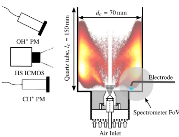
Air Inlet dc= 70 mm Quartz tube, lc = 150 mm Spectrometer FoV CH∗PM HS ICMOS OH∗PM Electrode
Figure 1: Schematic view of the SICCA-Spray burner. The air plenum is cut for concision. Chemiluminescence diagnostics include a high-speed intensified camera (HS ICMOS) and two photomultipli-ers (PM). An Abel transformed flame image (see Fig. 5) acquired at an equivalence ratio φ= 0.63 is shown in the background. A gray disk qualitatively indicates the field of view (FoV) of the spectrometer. The electrode is to scale with the flame image.
Figure 2: Direct imaging of the plasma discharge using the high-speed camera at 500 fps (false colors). Exposure time is 50µs to capture a single discharge. The red dots correspond to the tip of the electrode, the bottom of the image to the combustor backplane.
Moreover, liquid fuel atomizers are commonly located on the centerline to ensure a homogeneous spray dis-tribution, and the discharge might form between the electrode and the atomizer head. To avoid damaging this sensitive component, in the present study, the elec-trode is placed close to the lateral wall and the chamber backplane, in the outer recirculation zone (ORZ). Thus, the discharges will occur in an area where the reactive species have sufficient time to mix with the fuel and ox-idizer.
In this work, three fuels are considered: premixed methane-air (for a baseline), liquid heptane and liquid dodecane, which is comparatively less volatile [20]. We show that the LBO limit of these swirling flames is ex-tended with NRP discharges.
2. Experimental Setup
2.1. The SICCA-Spray Combustor
Experiments are carried out at atmospheric pressure in the SICCA-Spray combustor which is slightly mod-ified compared to previous spray ignition investiga-tions [20]. As shown in Fig. 1, the system consists of an air plenum followed by a swirling injection sys-tem (gray area) comprising a tangential channel swirler that leads to a convergent section with a final radius 2
rin j = 4 mm. This injector has a measured swirl
num-ber of 0.68 [20]. Liquid fuel is injected as a hollow cone spray (diamond-patterned triangle) by a simplex atomizer. When the system operates in the premixed mode, methane is mixed with the air flow using a cy-clonic mixing chamber located 3 m upstream of the air plenum. A compact flame is stabilized downstream of the dump plane inside a transparent quartz confinement tube. Spray characterization, performed at the nomi-nal operating condition (t0 in Tab. 1), indicates that for
both liquid fuels the mean Sauter diameter of droplets is D32 ≈ 30µm [20]. NRP discharges are created
be-tween the tip of an Inconel electrode and the combustor backplane (Fig. 2). The electrode tip is located 5 mm above the backplane and 24 mm from the centerline of the combustor, except in Sec. 4 where its position is var-ied. Pulses of 10-ns duration with an incident amplitude of 5 kV are generated by a FPG 10-30NM10 generator (FID Technology) at a repetition rate of 20 kHz. 2.2. Measurement Equipment
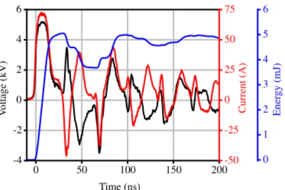
A 6-meter long coaxial cable (75Ω impedance) con-nects the generator and the electrode. A high voltage probe (Lecroy PPE20kV) and a current probe (Pear-son 6585) are placed midway on the cable and are used to monitor the deposited energy on an oscillo-scope (Lecroy HDO 6104) [21]. Typical voltage and current curves are shown in Fig. 3. The deposited en-ergy can be calculated from these curves because it has been verified that no energy is lost in the cable and because radiative losses are negligible [22]. In this study, the voltage is adjusted for every configura-tion so that the deposited energy remains constant at 5.00 mJ ± 0.25 mJ, corresponding to an average electri-cal power of 100 W ± 5 W.
Mass flow controllers (Bronkhorst EL-Flow) with a relative accuracy of ±7.5h and a repeatability better than ±2h monitor the flows of air and methane. A Bronkhorst CORI-Flow system is used for the liquid fuels (relative accuracy ±2h, repeatability better than ±0.75h). A high-speed intensified camera records the flame images (Photron FastCam APX-i2, 512 × 1024 pixels, 10−bit gray level depth, 500 images per second with an exposure time of 2 ms). It is equipped with a 45 mm lens and an optical bandpass filter centered at 431 nm to capture the emission of the CH∗radical. The field of view encompasses the whole combustion cham-ber, from the dump plane to the quartz tube outlet. Two photomultipliers (PM) measure the chemiluminescence signal from the flame. One is equipped with an optical bandpass interference filter centered at 308 nm to cap-ture the emission from the OH∗radical in the flame and
0 50 100 150 200 -4 -2 0 2 4 6 V oltage (kV) Time (ns) -50 -25 0 25 50 75 Current (A) 0 1 2 3 4 5 6 Ener gy (mJ)
Figure 3: Voltage (black) and current (red) traces recorded with NRP discharges in a dodecane flame. The energy curve (blue) is the integral of the current and voltage product. In this example, 5.00 mJ ± 0.25 mJ is sent by the pulser and 1.50 mJ ± 0.25 mJ is initially reflected. This energy is deposited during subsequent reflections at t = 90 ns and t= 180 ns. For detailed descriptions of the oscillograms, see [11, 21].
the other with a filter centered at 431 nm for the emis-sion of CH∗radicals. These sensors integrate the light
emission from the whole combustor volume. Their sig-nals, along with the flowrates, are recorded at 2 kHz. The PM signals are a qualitative indicator of the instan-taneous heat release rate of the flame, and are used to detect LBO when these signals drop to zero. When the discharge is active, other excited species, notably N∗2, emit in the same spectral ranges, and electromag-netic noise, captured by the acquisition chain, is present. This is managed by appropriate electromagnetic shield-ing, recording the signal with a delay of 35µs with re-spect to the pulsed discharge (using a BNC Model 577 gate-and-delay generator), and applying a low pass fil-ter in post-processing. This is found sufficient to reli-ably detect LBO even in the presence of the discharge. An OceanOptics Maya2000Pro deep-UV spectrometer is used to analyze the spontaneous emission from the flame and the plasma. The optical train consists of a small lens and an optical fiber. The field of view (FoV) schematically shown in Fig. 1 encompasses the entire discharge area and some of the ORZ with an integration time including several discharges (≈ 1 ms). Therefore, the spectra are representative of the brightest region of the plasma (the core) at the peak of the emission (end of the discharge).
2.3. Characterization of the plasma
In addition to the images in Fig. 2 and the electri-cal characterization in Fig. 3, Optielectri-cal Emission Spec-troscopy (OES) of the PAC dodecane flame is per-formed at four different flame operating conditions (φ = 0.87, 0.65, 0.60 and 0.53). The acquired spectra dis-played in Fig. 4 give a qualitative idea of the species
Figure 4: Typical emission spectra recorded in a dodecane flame as-sisted by NRP discharges (φ= 0.87, 0.65, 0.60 and 0.53). At 520 nm emission from Cr is visible (not to be confused for C2Swan emission).
It originates from the erosion of the Inconel electrode (≈ 20% Cr). For wavelengths longer than 500 nm, a continuum associated with thermal radiation from the burner and the quartz tube is present.
excited and produced by the discharge and the flame. Typical combustion species (CH* and OH* [23, 24]) are identified in these PAC spectra as well as in the spec-tra without PAC (not shown here). Strong peaks arising from the emission of CN∗are found, a feature also re-ported by Kim et al. [25] in a plasma-assisted premixed methane-air jet flame. No significant emission from C∗ 2
is detected. Atomic emission from oxygen O∗, nitrogen
N∗, and hydrogen H
αis observed. These features show
that the NRP discharges dissociate O2, N2and possibly
CO2, H2O and the fuel.
Stark broadening of the Hα line at 656 nm is used to determine the electron number density (ne) of the
plasma [26]. At φ = 0.87 and 0.65 (attached stable flames), ne= (1.4±0.2)×1017cm−3, which corresponds
to a degree of ionization about 10%. Several peaks are associated with the emission of N2(C). Using SPECAIR
[23], the rotational and vibrational temperatures are esti-mated: Trot= (3500±500)K and Tvib= (8000±1000)K.
As the emission is averaged in space and time by the spectrometer, the emission of N2(C) is representative
of the hottest region (center) of the plasma at the end of the pulse. At this instant, N2(C) is populated by
electron impact and therefore its rotational distribution mirrors that of N2(X) [12]. Owing to fast
rotational-translational relaxation at atmospheric pressure, the ro-tational temperature of N2(X) is close to the gas
tem-perature, therefore Tgas,plasma ' Trot = (3500 ± 500)K is
representative of the peak temperature at the end of the discharge. The quenching of N2excited states by O2 is
responsible for the increase in temperature and the dis-sociation of O2[12]. Both effects are favorable for the
flammability of the combustible mixture.
Table 1: Operating conditions for all fuels at the start of the air flow linear ramp (t0) and at the end (t∞ = 40 s). The bulk velocity ubis
defined at cold thermal conditions as ub= ˙mgas/πρrin j2 . The fuel mass
flow rate, thermal power and global equivalence ratio are respectively designated by ˙mf uel, P and φ.
˙ mf uel P φ ub(m s−1) (g h−1) (kW) t 0 t∞ t0 t∞ CH4 359 4.98 0.88 0.46 35 65 C7H16 400 4.95 0.87 0.45 32 62 C12H26 405 4.97 0.87 0.45 32 62
The temperature in the plasma Tgas,plasma ≈ 3500 K, higher than the adiabatic flame temperature (Tad <
2100 K), and the dissociation of O2 indicate that this
discharge is neither an NRP-corona nor an NRP-glow discharge [13]. ne is between the values reported
for nonequilibrium NRP-sparks [12], and for thermal sparks [21]. As neither N+ emission (500 nm) nor an electron continuum is observed in the spectra, the NRP-spark is necessarily of the nonequilibrium type. 2.4. Lean Blow Out Procedure
To avoid changing the fuel atomization properties, which are sensitive to the flow rate for simplex atomiz-ers [27], the fuel flow rates are kept constant. They are chosen so that the thermal power is almost the same for all fuels at P ≈ 5 kW. The ratio of electrical (NRP) to thermal (combustion) power is therefore equal to 2% for all cases. The LBO limit is determined by linearly vary-ing the air flow rate, startvary-ing from the nominal, well-characterized operating point of ˙mair = 1.94 g s−1[20]
and going up to ˙mair = 3.77 g s−1over a time period of
40 s. Before starting the air ramp, in order to ensure re-producibility, the burner is operated at the steady nomi-nal operating point until thermal equilibrium is reached. The operating conditions are summarized in Tab. 1.
3. Experimental Results for Different Fuels
The flame evolution during the air ramp, depicted in Fig. 5, shows flame images for both methane and heptane. Evolution of the flame shape is essentially the same for all three fuels with and without plasma. Starting from an “M” or “V” shaped flame at the nom-inal operating condition, the flame changes shape to burn both in the ORZ and at the top of the swirling jet at leaner operating points (φ ≈ 0.64), leading to an “M+ORZ” shape. Soon after, the flame starts to oscillate at a frequency close to 12 Hz for methane (φ = 0.58), and 7 Hz for liquid fuels (φ = 0.57 for heptane). These oscillations are investigated using the 4
φ
t
and ˙
m
air CH4 φ = 0.88 φ = 0.64 φ = 0.58 φ = 0.57 φ = 0.55 φ = 0.54 φ = 0.53 φ = 0.51 φ = 0.50 φ = 0.49 C7H16 φ = 0.87 φ = 0.63 φ = 0.57 NRP φ = 0.56 NRP φ = 0.55 NRP φ = 0.54 NRP φ = 0.53 NRP φ = 0.53 NRP φ = 0.52 NRP φ = 0.51Figure 5: Chemiluminescence (CH∗) images acquired using the high-speed camera. An Abel transform is performed to aid the identification of
the flame shape assuming azimuthal symmetry. From left to right, the air flow is increased starting at the nominal condition of Tab. 1. The first line shows the blow out sequence for a methane flame without PAC. The second line that for a heptane flame, without PAC down to φ= 0.57, and with PAC for leaner operating points. In the latter case, a darker band at the bottom of the combustor masks the luminosity of the discharges. The images are also noisier especially near the centerline. From φ= 0.62 up to φ = 0.56 for methane and from φ = 0.60 up to φ = 0.55 for heptane (without PAC), a low frequency oscillation is found (see Fig. 6). For those operating points, two opposite phase instants are shown. No change in flame shape or flame height is observed between PAC and non-assisted flames.
high speed camera. Images are processed using DMD (Dynamic Mode Decomposition [28]), and are shown as phase-averaged flame images in Fig. 6 for heptane. These low-frequency oscillations are essentially extinc-tion and reigniextinc-tion in the ORZ, as the flame oscillates between an “M+ORZ” and a “tulip” shape. The ORZ reignites by the propagation of flame kernels from the downstream side to the ORZ. The overall evolution is similar for all three fuels during the oscillation, although the frequency is higher for methane. This type of low-frequency oscillations occurring close to the LBO limit is investigated in [1]. DMD is also performed on the spark images (Fig. 2) acquired during the oscillation phase, but it shows no coherent motion of the spark at the frequency of the flame. These flame oscillations end either by LBO, or by stabilization of the flame in a fairly long “tulip” shape. As the air flow rate is increased, the “stem” part of the flame becomes longer, and the “petals” move downstream until LBO occurs. Flame oscillations between two stable flame regions are also
Table 2: Probability ˆp of flame blow out during the oscillation phase for each fuel with and without PAC (lower is better). At least 10 ex-periments are performed for each case. The 95% statistical confidence interval is computed using the Clopper-Pearson method and is indi-cated in parenthesis.
ˆpnot PAC ˆpPAC
CH4 0.13 (−0.11,+0.26) 0 (+0.26)
C7H16 1.00 (−0.21) 0.27(−0.21,+0.34)
C12H26 1.00 (−0.28) 0.26(−0.17,+0.25)
reported by Kim et al. [5] during LBO characterization of a premixed swirling flame with PAC.
As indicated previously, after the oscillations the flame either suddenly blows out or continue to burn while the equivalence ratio decreases. Table 2 indicates the probability ˆp of flame blow out during the oscil-lations for each fuel with and without PAC. The im-provement is moderate for premixed methane and air, which already features good resistance to LBO without PAC. A statistically significant extension of the LBO
ϕ = 0 π/3 3π/8 2π/3 π 4π/3 5π/3
Figure 6: Phase averaged images of flame oscillation with heptane fuel (φ= 0.57, not PAC). Flame images are acquired using the high-speed camera and are then processed using DMD, which shows a pre-dominant mode at 7.5 Hz. An Abel transform is applied.
is observed using PAC in heptane and dodecane spray flames. For these fuels, without PAC, the flame is sys-tematically blown out during the oscillating phase, but is much more robust with NRP discharges, leading to a significant improvement of the LBO limit.
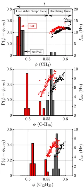
The improvement of the LBO limit with plasma-assistance is also represented in Fig. 7, where the his-tograms indicate the global equivalence ratio at LBO (φLBO) with (red) and without (black) NRP discharges.
Figure 7 shows for each fuel the flame oscillation fre-quency foscas a function of φ (right axis, dots). In each
case, a set of repeated experiments is presented. For all three fuels, the flame oscillation regime starts and ends at a leaner operating point with NRP discharges. Two observations can be drawn from these results: firstly, as φ decreases, there is a decrease in the oscillation fre-quency for all three fuels. Secondly, the frefre-quency trend is similar with and without plasma assistance.
For methane, the end of the oscillating regime is nearly the same with and without PAC. The flame sta-bilizes as a “tulip” shape after the oscillation. For two of the tests without NRP discharges, one observes LBO during the oscillation phase. For heptane and dode-cane, without plasma assistance, LBO always occurs during flame oscillations1. When the NRP discharges
are turned on, the flame is sustained after the oscillation phase and blows out under leaner conditions2. The in-creased LBO limit with PAC is quantified in Fig. 8 for all three fuels. The LBO limit (brown) is extended by ∆φ = 0.05 for both liquid fuels, and ∆φ = 0.018 for methane. The beginning of the low frequency
oscilla-1If the NRP discharges are turned on immediately after the
extinc-tion, the flame does not reignite.
2If the NRP discharges are turned off once the flame overcomes
the oscillating phase, the flame continues to burn until LBO at φ ≈ 0.52. This indicates that the “tulip” flame can exist without plasma. However, this state cannot be reached without NRP discharges and the extinction of the “tulip” flame is still leaner with plasma assistance.
Oscillating flame Lean stable “tulip” flame
t
∆φOsc. PAC
not PAC
Figure 7: Probability of extinction (histogram, left axis) and fre-quency of oscillation (dots, right axis) as a function of equivalence ratio. Experiments with (red) and without (black) plasma assistance are shown. For each experiment, a spectrogram of the OH∗PM
sig-nal is computed, and during the oscillation phase depicted in Fig. 6, a strong peak at low frequency is visible. Each dot represents this peak frequency for an experiment, computed on a window of 1 s, and only during the oscillation phase. The periodogram is computed using short-time Fourier transform with a frequency resolution of 0.25 Hz and a temporal resolution of 0.5 s. This approach allows for a clear identification of the limits and frequency of the flame oscillations as a function of φ.
Figure 8: Shift in equivalence ratio,∆φ, at LBO (brown) and at the start of the oscillations (blue), when NRP discharges are applied. Higher values indicate a stronger, more positive, effect of the plasma assistance. The uncertainty intervals are estimated from the repeata-bility of the mass flow controllers and from bootstrapping.
tion is also delayed by∆φ ≈ 0.02 for all three fuels. At this point, it is useful to briefly compare these values with the results of other studies of the improve-ment of the LBO limit by PAC in similar combustors (premixed CH4-air swirling flames at atmospheric
pres-sure). In [19], a variable swirl injector is used with a continuous microwave plasma discharge. The flame shape differs significantly from that of SICCA-Spray and, without plasma-assistance, LBO occurs between 0.85 < φLBO < 1.3 (depending on the flow rate).
Us-ing PAC with an electrical to thermal power ratio of 9% yields a 43% improvement on φLBO in their
configura-tion. However comparison with the present work is not possible given the difference in flame and flow topolo-gies. The combustor used in [5] is closest to SICCA-Spray. The flame shapes and LBO limits (0.5 < φLBO<
0.54 without PAC) are also similar. Using a dielectric barrier discharge applied continuously, the LBO is re-duced down to 0.45 < φLBO < 0.48 in [5], which is
comparable with results of the present work. In [6], a two-stage coaxial swirling injector (propane-air) is used with NRP discharges. The LBO performance signif-icantly depends on the air flow split between the two stages of the injector, the primary stage acting as a pilot flame. At a low power setting, PAC reduces φLBO for
the primary stage from 2 to 0.55, a value close to what is observed in the present study.
4. Impact of the Electrode Position
As already indicated it is not possible to operate the discharges at r/rin j < 1, because they would damage
the liquid fuel atomizer head. Figure 9 shows the re-sults obtained by varying the radial position of the elec-trode and measuring the LBO limit from repeated ex-periments with heptane. r/rin j = 6 is optimal for this
test rig in terms of effectiveness and repeatability. This
Nominal position
Figure 9: For the experiments presented in this figure, the radial position of the electrode is varied between r = rin j = 4 mm and
r = 7 rin j = 28 mm. The dots indicate for each electrode position
the global equivalence ratio at blow out φLBOwith (red) and without
(black) PAC. Each dot corresponds to a single experiment.
may be linked to the structure of the flame, to the asso-ciated flow and more specifically to the location of the ORZ. The typical shape of a heptane flame at φ = 0.63 is “M+ORZ” (see Fig. 1). From this pattern and from previously measured velocity profiles (in nonreactive, unconfined conditions [20], and in reactive, confined and steady conditions [29]), one may infer that near the combustor backplane the ORZ extends from r/rin j = 3
to r/rin j = 6. This region is filled with hot gases at
relatively low velocity and turbulent intensity, with an augmented residence time, and a longer convective de-lay to the base of the flame. In the outer region, beyond 6 rin jthe flow is cooled down by the wall. Between the
injector rim and r/rin j = 2 the flow is relatively fast,
cold and turbulent. It is suggested by [18] that an elec-trode placement in a relatively slow recirculation zone will favor plasma induced chemical effects. This ex-plains why the electrode location at r/rin j= 6 provides
the best performance in terms of LBO improvement.
5. Conclusion
This study is focused on the extension of the lean blow out (LBO) limit by NRP discharges in spray and perfectly premixed swirled flames at atmospheric pres-sure. Both liquid (heptane and dodecane) and gaseous (methane) fuels are examined. For these experiments, the fuel flow rate is kept constant, and the air flow rate is slowly increased until LBO occurs. The NRP dis-charges are applied at 20 kHz and the ratio of electrical to thermal power is 2%. Three phases are identified in the blow out sequence: the first stage sees flames ini-tially in a “V” or “M” shape burning further out in the outer recirculation zone (ORZ). In the second phase, the flames oscillate at a low frequency. Perfectly premixed flames stabilize in a “tulip” shape after the oscillations (third phase), until LBO occurs. For these flames, LBO
occurs at a leaner condition with the use of NRP dis-charges. For non-assisted spray flames, LBO systemat-ically occurs during the oscillations. If NRP discharges are used, spray flames can be stabilized in a “tulip” shape beyond the region where oscillations occur. The LBO limit is thereby greatly extended. The position of the electrode is identified as a critical factor for the ef-fectiveness of the PAC system. The outer edge of the ORZ is found to be the most favorable location, both in terms of LBO performance and ease of placement in many practical systems.
Acknowledgments
Support is provided by France’s ANR (FASMIC ANR16-CE22-0013; PASTEC ANR16-CE22-0005) and the EU Horizon2020 ANNULIGHT program (765998).
References
[1] S. K. Dhanuka, J. E. Temme, J. F. Driscoll, Lean-limit com-bustion instabilities of a lean premixed prevaporized gas turbine combustor, Proc. Combust. Inst. 33 (2) (2011) 2961 – 2966. [2] J. K. Lefkowitz, P. Guo, T. Ombrello, S. H. Won, C. A. Stevens,
J. L. Hoke, F. Schauer, Y. Ju, Schlieren imaging and pulsed det-onation engine testing of ignition by a nanosecond repetitively pulsed discharge, Combust. Flame 162 (6) (2015) 2496–2507. [3] D. A. Lacoste, J. P. Moeck, D. Durox, C. Laux, T. Schuller,
Effect of nanosecond repetitively pulsed discharges on the dy-namics of a swirl-stabilized lean premixed flame, J. Eng. Gas Turb. Power 135 (10) (October 2013).
[4] W. Kim, J. Snyder, J. Cohen, Plasma assisted combustor dynam-ics control, Proc. Combust. Inst. 35 (3) (2015) 3479–3486. [5] G. T. Kim, C. S. Yoo, S. H. Chung, J. Park, Effects of
non-thermal plasma on the lean blowout limits and CO/NOx emissions in swirl-stabilized turbulent lean-premixed flames of methane/air, Combust. Flame 212 (2020) 403–414.
[6] S. Barbosa, G. Pilla, D. A. Lacoste, P. Scouflaire, S. Ducruix, C. O. Laux, D. Veynante, Influence of nanosecond repetitively pulsed discharges on the stability of a swirled propane/air burner representative of an aeronautical combustor, Philos. Trans. R. Soc. A 373 (2048) (2015) 20140335.
[7] A. Starikovskiy, N. Aleksandrov, Plasma-assisted ignition and combustion, Prog. Energ. Combust. 39 (1) (2013) 61 – 110. [8] S. Starikovskaia, Plasma-assisted ignition and combustion:
nanosecond discharges and development of kinetic mechanisms, J. Phys. D: Appl. Phys. 47 (15) (2014) 353001.
[9] I. Adamovich, W. Lempert, Challenges in understanding and predictive model development of plasma-assisted combustion, Plasma Phys. Controlled Fusion 57 (1) (2014) 014001. [10] Y. Ju, J. Lefkowitz, C. Reuter, S. Won, X. Yang, S. Yang,
W. Sun, Z. Jiang, Q. Chen, Plasma assisted low temperature combustion, Plasma Chem. Plasma Process. 36 (2016) 85–105. [11] C. Dumitrache, A. Gallant, N. Minesi, S. Stepanyan, G. D.
Stancu, C. O. Laux, Hydrodynamic regimes induced by nanosecond pulsed discharges in air: mechanism of vorticity generation, J. Phys. D: Appl. Phys. 52 (36) (2019) 364001.
[12] D. L. Rusterholtz, D. A. Lacoste, G. D. Stancu, D. Z. Pai, C. O. Laux, Ultrafast heating and oxygen dissociation in atmospheric pressure air by nanosecond repetitively pulsed discharges, J. Phys. D: Appl. Phys. 46 (46) (2013) 464010.
[13] D. Z. Pai, D. A. Lacoste, C. O. Laux, Transitions between corona, glow, and spark regimes of nanosecond repetitively pulsed discharges in air at atmospheric pressure, J. Phys. D: Appl. Phys. 107 (9) (2010) 093303.
[14] M. S. Bak, S.-K. Im, M. G. Mungal, M. A. Cappelli, Studies on the stability limit extension of premixed and jet diffusion flames of methane, ethane, and propane using nanosecond repet-itive pulsed discharge plasmas, Combust. Flame 160 (11) (2013) 2396 – 2403.
[15] M. A. Boumehdi, S. A. Stepanyan, P. Desgroux, G. Van-hove, S. M. Starikovskaia, Ignition of methane- and n-butane-containing mixtures at high pressures by pulsed nanosecond dis-charge, Combust. Flame 162 (4) (2015) 1336–1349.
[16] D. A. Xu, D. A. Lacoste, C. O. Laux, Ignition of Quiescent Lean Propane–Air Mixtures at High Pressure by Nanosecond Repeti-tively Pulsed Discharges, Plasma Chem. Plasma Process. 36 (1) (2016) 309–327.
[17] G. Pilla, D. Galley, D. Lacoste, F. Lacas, D. Veynante, C. Laux, Stabilization of a turbulent premixed flame using a nanosec-ond repetitively pulsed plasma, IEEE Trans. Plasma Sci. 34 (6) (2006) 2471–2477.
[18] C. Kong, Z. Li, M. Ald´en, A. Ehn, Stabilization of a turbu-lent premixed flame by a plasma filament, Combust. Flame 208 (2019) 79 – 85.
[19] R. Rajasegar, C. M. Mitsingas, E. K. Mayhew, S. Hammack, H. Do, T. Lee, Effects of continuous volumetric direct-coupled nonequilibrium atmospheric microwave plasma discharge on swirl-stabilized premixed flames, IEEE Trans. Plasma Sci. 44 (1) (2016) 39–48.
[20] K. Prieur, D. Durox, J. Beaunier, T. Schuller, S. Candel, Ig-nition dynamics in an annular combustor for liquid spray and premixed gaseous injection, Proc. Combust. Inst. 36 (3) (2017) 3717–3724.
[21] N. Minesi, S. A. Stepanyan, P. B. Mariotto, G.-D. Stancu, C. O. Laux, Fully ionized nanosecond discharges in air: the thermal spark, Submitted to Plasma Sources Sci. Technol. (2020). [22] R. Maly, M. Vogel, Initiation and propagation of flame fronts in
lean CH4-air mixtures by the three modes of the ignition spark, Symp. (Int.) Combust. 17 (1) (1979) 821–831.
[23] C. O. Laux, T. G. Spence, C. H. Kruger, R. N. Zare, Optical di-agnostics of atmospheric pressure air plasmas, Plasma Sources Sci. Technol. 12 (2003) 125–138.
[24] A. G. Gaydon, The Spectroscopy of Flames, Springer Nether-lands, 1974.
[25] W. Kim, H. Do, M. G. Mungal, M. A. Cappelli, Plasma-discharge stabilization of jet diffusion flames, IEEE Trans. Plasma Sci. 34 (6) (2006) 2545–2551.
[26] M. A. Gigosos, M. ´A. Gonz´alez, V. Carde˜noso, Computer simulated Balmer-alpha, -beta and -gamma Stark line profiles for non-equilibrium plasmas diagnostics, Spectrochim. Acta B 58 (8) (2003) 1489–1504.
[27] A. H. Lefebvre, Atomization and Sprays, CRC Press, 1989. [28] P. J. Schmid, Dynamic mode decomposition of numerical and
experimental data, J. Fluid Mech. 656 (2010) 5–28.
[29] T. Lancien, Numerical study of two-phase ignition in annular multi-burner combustors, Ph.D. thesis, Universit´e Paris-Saclay.