Département de Génie Civil
FLEXURAL BEHAVIOUR OF RECTANGULAR
FRP TUBES FULLY OR PARTIALLY FILLED
WITH REINFORCED CONCRETE
Comportement en flexion de tubes en PRF rectangulaires entièrement ou
partiellement remplis de béton armé
Thèse de doctorat Spécialité: génie civil
Ahmed Mohamed Abouzied SOLIMAN
A dissertation submitted in partial fulfillmentof the requirements for the degree of Doctor of Philosophy
(Civil Engineering)
Jury: Prof. / Radhouane MASMOUDI, PE., PhD (directeur de recherche) Prof. / Omar CHAALLAL. PE., PhD
Prof. / Ehab EL-SALAKAWY, PE., PhD
Chief, Structures Division, MTQ / Gérard DESGAGNÉ, PE., M.Sc. Prof. / Richard GAGNÉ, PE., PhD
i
Recently, fiber-reinforced polymer (FRP) composite materials have been used in the field of civil engineering constructions especially in corrosive environments. They can be used as internal reinforcement for beams, slabs, and pavements, or as external reinforcement for rehabilitation and strengthening different structures. One of their innovative applications is the concrete-filled FRP tubes (CFFTs) which are becoming an alternative for different structural members such as piles, columns, bridge girders, and bridge piers due to their high performance and durability. In such integrated systems, the FRP tubes act as stay-in-place forms, protective jackets for the embedded concrete and steel, and as external reinforcement in the primary and secondary direction of the structural member.
Extensive research was developed on CFFTs as columns, but comparatively limited research was carried out on CFFTs as beams especially those with rectangular sections. The circular sections exhibit magnificent confinement efficiency in case of columns. However, the rectangular sections have higher moment of inertia and flexural stiffness to resist the applied loads and deformations in case of beams. Moreover, the construction and architectural requirements prefer the rectangular section of beams, rather than the circular beams, due to its stability during installation and its workability during connecting to other structural members like slabs and columns. Also, CFFTs that are completely filled with concrete are not optimal for applications governed by pure bending, because the excess weight of the cracked concrete below the neutral axis may increase the transportation and installation cost. This dissertation presents experimental and theoretical investigations on the flexural behaviour of rectangular CFFT beams with steel rebar. These hybrid FRP-concrete-steel tubular rectangular beams contain outer rectangular filament-wound glass-FRP (GFRP) tubes to increase the sectional moment of inertia, to provide flexural and shear reinforcement, and to protect the inner structural elements (concrete and steel) against corrosion. The outer tubes were fully-or-partially filled with concrete and were reinforced with steel rebar at the tension side only. Inner hollow circular or square filament-wound GFRP tubes, shifted toward the tension zone, were provided inside the CFFT beam to eliminate the excess weight of the
ii
were roughened by sand coating to fulfill the full composite action of such hybrid section. Several test variables were chosen to investigate the effect of the outer and inner tubes thickness, fibers laminates, and shape on the flexural behaviour of such hybrid CFFT beams. To fulfil the objectives of the study, twenty-four full-scale beam specimens, 3200 mm long and 305×406 mm2 cross section, were tested under a four-point bending load. These specimens include eight fully-CFFT beams with wide range of tube thickness of 3.4 mm to 14.2 mm, fourteen partially-CFFT beams with different outer and inner tubes configurations, and two conventional steel-reinforced concrete (RC) beams as control specimens.
The results indicate outstanding performance of the rectangular fully and partially-CFFT beams in terms of strength-to-weight ratio and ductility compared to the RC beams. The fully-CFFT beams with small tube thickness failed in tension by axial rupture of fibers at the tension side. While, the fully-CFFT beams with big tube thickness failed in compression by outward buckling of the outer tube compression flange with warning signs. The results indicate also that the flexural strength of the fully-CFFT beams was ascending nonlinearly with increasing the tubes thickness until a certain optimum limit. This limit was evaluated to define under-and-over-reinforced CFFT sections, and consequently to define the tension and compression failure of fully-CFFT beams, respectively. The inner hollow tubes act positively in reinforcing the partially-CFFT beams and confining the concrete core at the compression side. The strength-to-weight ratio of the partially-CFFT beams attained higher values than that of the corresponding fully-CFFT beams. Generally, the partially-CFFT beams failed gradually in compression due to outward buckling of the outer tube compression flange with signs of confining the concrete core at the compression side. The inner circular voids pronounced better performance than the square inner voids, however they have the same cross sectional area and fiber laminates.
Theoretical section analysis based on strain compatibility/equilibrium has been developed to predict the moment-curvature response of the fully-CFFT section addressing the confinement and tension stiffening of concrete. The analytical results match well the experimental results in terms of moment, deflection, strains, and neutral axis responses. In addition, analytical
iii
on these investigations, a new power and assumptions were proposed to Branson’s equation to predict well the effective moment of inertia of the CFFT section. These assumptions consider the effect of the GFRP tube strength, thickness and configuration, in addition to the steel reinforcement ratio. The proposed equations predict well the deflection in the pre-yielding and post-pre-yielding stages of the hybrid FRP-concrete-steel CFFT rectangular beams. Keywords: Fiber-Reinforced Polymer, Filament Winding, Concrete-Filled FRP Tube, Beams, Flexural behaviour, Deflection.
v
Les matériaux composites en polymère renforcé de fibres (PRF) ont récemment été utilisés dans le domaine des constructions de génie civil, en particulier dans les environnements corrosifs. Elles peuvent être utilisées comme une armature interne pour des poutres, dalles et les trottoirs, ou comme une armature externe pour la réhabilitation et le renforcement de différentes structures. L'une de leurs applications novatrices est les tubes de polymères renforcés de fibres remplis de béton (TPFRB1) qui sont en train de devenir une alternative pour divers éléments structuraux tels que les pieux, les colonnes, les poutres et les piliers de ponts en raison de leur haute performance et durabilité. Dans de tels systèmes intégrés, les tubes PRF agissent comme un coffrage permanent, une chemise protectrice pour le béton et l'acier encastrés, et comme une armature externe dans les directions longitudinale et transversale de l'élément structural.
La recherche a été concentrée sur les TPRFB comme des colonnes, mais très peu de recherche a été effectué les TPRFB comme des poutres particulièrement celles à section rectangulaire. La section circulaire présente une efficacité de confinement efficace en cas de colonnes. Toutefois, la section rectangulaire a un moment d'inertie plus élevé et une rigidité flexionnelle plus efficace pour résister les charges appliquées et les déformations dans le cas des poutres. Par ailleurs, les travaux de construction et les exigences architecturales préfèrent la section rectangulaire des poutres, plutôt que les poutres circulaires, en raison de sa stabilité pendant l'installation et sa maniabilité lors de la connexion à d'autres membres structuraux comme les dalles et les colonnes. En outre, les poutres TPRFB qui sont complètement remplis de béton ne sont pas optimales pour les applications contrôlées par la flexion pure, puisque le béton fissuré en dessous de l'axe neutre ne contribue pas à la résistance et augmente le poids propre et les coûts de transport et d'installation.
Cette thèse présente des études théoriques et expérimentales sur le comportement en flexion de poutres rectangulaires (TPRFB) en béton armé. Ces poutres rectangulaires tubulaires hybrides en PRF-béton-acier sont composées de tubes rectangulaires externes fabriquées par
vi
entièrement ou partiellement remplies de béton. Des tubes intérieurs ( de section circulaires ou carrés) en polymères renforcés de fibres de verre (PRFV) sont positionnés dans la zone tendue de la poutre afin de réduire le poids et d’éliminer le béton fissuré en traction. Pour augmenter l'action composite de la section hybride, les surfaces des tubes adjacents au béton ont été rendues rugueuses par enrobage de sable. Plusieurs variables ont été choisis pour étudier l'effet de l’épaisseur des tubes extérieurs et intérieurs, les laminés de fibres, et la forme sur le comportement en flexion de ces poutres hybrides (TPRFB). Pour atteindre les objectifs de l’étude, vingt-quatre échantillons de poutre pleine grandeur, ayant une longueur de 3200 mm et une section transversale de 305×406 mm2, ont été testés sous une flexion à quatre points. Ces échantillons comprennent huit poutres de TPRFB entièrement remplis avec une large gamme d'épaisseur du tube externe de 3.4 mm à 14.2 mm, quatorze poutres de TPRFB partiellement remplis avec différentes configurations de tubes extérieurs et intérieurs, et deux poutres en béton armé conventionnel, comme échantillons de référence.
Les résultats indiquent une performance exceptionnelle des poutres rectangulaires de TPRFB entièrement et partiellement remplies en termes du rapport de la résistance sur la masse et de la ductilité par rapport aux poutres en béton armé conventionnel. Les poutres de TPRFB entièrement remplies avec un tube de petite épaisseur ont rompu de façon moins ductile en tension par rupture axiale des fibres. Les poutres de TPRFB entièrement remplies et ayant une grande épaisseur ont rompu de façon ductile en compression par flambage local vers l’extérieur des parois en compression du tube externe. Les résultats indiquent également que la résistance à la flexion des poutres de TPRFB entièrement remplies augmente d’une façon non linéaire avec l'augmentation de l'épaisseur des tubes jusqu'à une certaine limite optimale. Cette limite a été évaluée pour définir les sections TPRFB sous-armées et surarmées et, par conséquent, pour définir la rupture en tension et en compression des poutres de TPRFB entièrement remplies, respectivement. Les tubes creux intérieurs agissent positivement dans le renforcement des poutres de TPRFB partiellement remplies et en confinant le noyau de béton du côté en compression. En général, les poutres de TPRFB partiellement remplies ont rompu en compression par flambage local vers l'extérieur des parois en compression du tube
vii taux de PRF.
Une analyse théorique basée sur la compatibilité des déformations d’une section en flexion a été développée pour prédire la réponse moment-courbure de la poutre TPRFB en tenant compte des pourcentages de confinement externe et interne. Les résultats analytiques et les résultats expérimentaux s’accordent en termes de moment, flèche, déformations, et positions de l'axe neutre. En outre, une étude analytique a été menée afin d'examiner la validité des codes de conception nord-américains pour prédire la réponse en flexion des poutres TPRFB. En se basant sur les résultats de ces études, de nouvelles équations ont été proposées pour mieux prédire le moment effectif d'inertie de la section et une nouvelle procédure de conception pour prédire les capacités ultimes. Ces équations considèrent l'effet de la résistance des tubes en PRFV externe et interne que le taux d’armature en acier. En outre, ils prédisent bien la flèche dans les phases avant et après la limite élastique des poutres rectangulaires hybrides à haute performance.
Mots-clés : Polymère renforcé de fibres (PRF), enroulement filamentaire, Tubes de PRF remplis de béton, poutres, comportement en flexion, flèche.
ix
EDUCATION
B.Sc. in civil engineering, Faculty of Engineering, Helwan University, Cairo, Egypt, 2004. The undergraduate grade was Distinction with honor rank (91.44%) and the 1st of my colleagues (1/300).
M.Sc. degree in RC structures. M.Sc. thesis titled "Behaviour of flat slab-corner column connection", Civil Engineering department, Faculty of Engineering, Helwan University, Cairo, Egypt, 2009.
Now, Ph.D. candidate in the field of RC structures, Civil Engineering department, Faculty of Engineering, Sherbrooke University, Sherbrooke, Quebec, Canada.
The candidate has participated in the following publications during his doctorate study at Sherbrooke University:
US PATENT 61/897,429
R. Masmoudi and A. Abouzied, (2013). “Composite structural member, method for manufacturing same, and connecting assemblies for composite structural members”, International Application Number: PCT/CA2014/051045”, US Patent 61/897,429.
JOURNAL PUBLICATIONS:
1) A. Abouzied and R. Masmoudi, (2015). “Structural performance of new fully and partially concrete-filled rectangular FRP-tube beams”, Elsevier Journal of Construction and Building Materials, Vol.101: 652–660.
2) A. Boumarafi, A. Abouzied, R. Masmoudi, (2015). “Harsh environments effects on the axial behaviour of circular concrete-filled fibre reinforced-polymer (FRP) tubes”, Elsevier Journal of Composites: Part B, Vol.83: 81-87.
3) A. Abouzied and R. Masmoudi, (2016). “New high-performance rectangular FRP-tube beams partially filled with concrete”, ACI–Special Publication, SP-15.
x
of Engineering Structures, ENGSTRUCT-S-16-00088, (In review).
5) A. Abouzied and R. Masmoudi, (2016). “Effective moment of inertia of rectangular FRP-tube beams fully or partially filled with reinforced concrete”, Journal of Structural Engineering ASCE, (Submitted).
6) A. A. Ahmed, M. Hassan, H. Mohamed, A. Abouzied, and R. Masmoudi, (2016). “Axial behavior of circular CFFT long columns internally reinforced with steel, carbon and glass longitudinal bars”, Elsevier Journal of Engineering Structures, ENGSTRUCT-D-15-01381, (In review).
CONFERENCE PUBLICATIONS:
1) A. Abouzied, M. Ammar, R. Masmoudi, (2011). “Nanoparticles effect on the physical and mechanical properties of FRP filament-winded composites”, Proceedings of 26th ASC Annual Technical Conference (the Second Joint US-Canada Conference on Composites), Montreal, Canada, September 2011, pp 1131-1140.
2) A. Abouzied, R. Masmoudi, R. Gagne, A. Tagnit-Hamou, (2012). “Effect of nanoparticles added to vinyl ester resin on the compressive behaviour of square concrete-filled GFRP tubes”, Proceedings of 6th International Conference on Advanced Composite Materials in Bridges and Structures ACMPS-VI, Kingston, Canada, May 2012, pp 496-503.
3) A. Abouzied, M. Ammar, R. Masmoudi, (2012). “Nanoparticles effect on FRP filament-winded composites performance”, Proceedings of CICE 6th International Conference on FRP Composites in Civil Engineering (CICE), Rome, Italy, June 2012. 4) A. Abouzied and R. Masmoudi, (2012). “Square columns confined by GFRP tube or
steel ties”, Proceedings of FRPRCS 11th International Symposium on fiber reinforced Polymer for reinforced Concrete structures, Portugal, December 2012.
5) A. Abouzied and R. Masmoudi, (2013). “Performance of square concrete-filled FRP tubes versus steel reinforced concrete columns”, Proceedings of 2nd conference on Smart Monitoring, Assessment and Rehabilitation of Civil Structures SMAR 2013, Istanbul, Turkey, September 2013.
xi
Structural Specialty Conference CSCE, Halifax, NS, May 2014, CST-171-(1-10). 7) A. Abouzied and R. Masmoudi, (2015). “New design of rectangular partially
concrete-filled filament-wound FRP tube beam”, Proceedings of 3rd conference on Smart Monitoring, Assessment and Rehabilitation of Civil Structures SMAR 2015, Antalya, Turkey, September 2015.
8) R. Masmoudi, A. Abouzied, H. Mohamed, (2015) “New hybrid concrete filled FRP stay-in-place forms as high-performance structural members”. Proceedings of 13th Arab Structural Engineering Conference ASEC, University of Blida, Blida, Algeria, December 2015.
9) A. Abouzied and R. Masmoudi, (2016). “Deflection of Rectangular Concrete-Filled FRP Tube Beams”, Proceedings of 7th International Conference on Advanced Composite Materials in Bridges and Structures ACMPS-VII, Vancouver, British Columbia, Canada, August 2016 (Submitted).
10) A. Abouzied and R. Masmoudi, (2016). “Flexural behaviour of rectangular FRP-tubes filled with reinforced concrete: experimental and analytical investigations”, Proceedings of 5th International Structural Specialty Conference CSCE, London, ON, Canada, June 2016, (Submitted).
xiii
Thanks to Almighty ALLAH for the gracious kindness in all the endeavors, I have taken up in my life.
I would like to express my sincere greatest appreciation and thanks to my supervisor Professor Radhouane Masmoudi for offering me the opportunity to work on such a challenging subject. I am so proud to work with him. All of the guidance, insight, helpful advice, and constant encouragement provided throughout the course of the dissertation are greatly appreciated. I owe him an unbelievable amount of gratitude for his prominent role in helping me to achieve one of the greatest accomplishments in my life.
Sincere words of thanks must also go to the technical staff at the Structures Laboratory, Department of Civil Engineering at Sherbrooke University, especially, Mr. Éric Beaudoin, for his assistance during the fabrication, construction and testing of the specimens.
In addition, the author is thankful to Natural Science and Engineering Research Council of Canada (NSERC) and the Fonds québécois de la recherche sur la nature et les technologies (FQRNT) for their partially sponsored financial support. The authors also acknowledge the contribution of the Canadian Foundation for Innovation (CFI) for the infrastructure used to conduct testing.
My deep appreciation and thanks are expressed to my father, my mother, my brothers for their support, endless love and encouragement.
Finally, I owe my deepest love and appreciation to my dear wife for her steadfast support and continuous encouragement. She was always there to give me the push for this challenge and to face all life obstacles. I cannot present this work without expressing my love to my son Omar who wish to be engineer like me, and my daughter Aliaa who enlightened my life with her smile.
xv
ABSTRACT ... i
RÉSUMÉ ...v
PRESENTATION OF THE CANDIDATE ... ix
ACKNOWLEDGEMENT ... xiii
TABLE OF CONTENTS ...xv
LIST OF TABLES ... xxi
LIST OF FIGURES ... xxiii
CHAPTER 1: INTRODUCTION ...1
1.1 GENERAL ... 1
1.2 RESEARCH OBJECTIVES ... 4
1.3 METHODOLOGY ... 5
1.4 THESIS OUTLINES ... 6
CHAPTER 2: LITERATURE REVIEW ...9
2.1 INTRODUCTION ... 9 2.2 FRP COMPOSITE MATERIALS ... 10 2.2.1 Fibers... 10 2.2.1.1 Glass Fibers ... 11 2.2.1.2 Carbon Fibers ... 11 2.2.1.3 Aramid Fibers ... 12 2.2.2 Polymer Resins ... 12 2.2.2.1 Polyester Resin ... 13 2.2.2.2 Epoxy Resin ... 13
2.2.2.3 Vinyl Ester Resin ... 13
2.2.3 Fillers ... 14
2.3 FRP COMPOSITE MANUFACTURING PROCESSES ... 14
2.3.1 Pultrusion Process ... 15
xvi
2.3.5 Filament Winding Process ... 16
2.4 CONCRETE-FILLED FRP TUBES UNDER FLEXURE ... 18
2.4.1 General Review ... 18
2.4.2 Effect of Inner Concrete Core ... 19
2.4.3 Effect of Concrete Strength ... 19
2.4.4 Effect of Tube Thickness ... 20
2.4.5 Effect of Tube Laminate Structure (Fibers Orientation)... 22
2.4.6 Effect of Steel and FRP Rebar ... 23
2.4.7 Effect of Bond ... 25
2.4.8 Effect of Inner Hole ... 27
2.5 LIGHTWEIGHT HYBRID FRP-CONCRETE COMPOSITE SECTIONS ... 28
CHAPTER 3: EXPERIMENTAL PROGRAM ...47
3.1 INTRODUCTION ... 47
3.2 FABRICATION OF GFRP TUBES ... 47
3.3 TESTS ON GFRP TUBES ... 49
3.3.1 Fiber Content ... 49
3.3.2 Glass Transition Temperature ... 50
3.3.3 Mechanical Performance of GFRP Tubes ... 51
3.4 TEST VARIABLES ... 52
3.5 BEAM SPECIMENS ... 53
3.6 FORMWORKS AND CASTING ... 54
3.7 TEST SETUP AND INSTRUMENTATIONS ... 55
CHAPTER 4: FLEXURAL BEHAVIOUR OF FULLY-CFFT RECTANGULAR BEAMS ...75
4.1 ABSTRACT ... 76
4.2 INTRODUCTION ... 77
xvii
4.4.2 Flexural Behaviour of the Control RC Beams ... 81
4.4.3 Failure Patterns of Fully-CFFT Beams ... 81
4.4.4 Effect of Cycling Load... 84
4.4.5 Flexural Performance of Fully-CFFT Beams ... 84
4.4.5.1 Effect of Steel Reinforcement in Fully-CFFTs ... 85
4.4.5.2 Effect of Outer Tube Laminate Structure ... 87
4.4.5.3 Effect of Outer Tube Thickness... 88
4.4.6 Cracking Moment of Rectangular Fully-CFFT Beams ... 90
4.5 ANALYTICAL MODELLING OF RECTANGULAR CFFT BEAMS UNDER FLEXURE ... 93
4.5.1 Description of the Analytical Model ... 94
4.5.2 Constitutive Relationships of Materials ... 95
4.5.2.1 Steel Model ... 95
4.5.2.2 FRP Tube Model ... 96
4.5.2.3 Concrete Model ... 98
4.5.3 Procedure of Analysis ... 101
4.5.4 Verification of the Model... 102
4.6 PARAMETRIC STUDY ... 104
4.6.1 Effect of Steel Reinforcement Ratio ... 104
4.6.2 Effect of Tube Stiffness or Laminate Structure ... 105
4.6.3 Effect of Tube Thickness ... 105
4.6.4 Effect of Concrete Strength ... 106
4.7 CONCLUSIONS ... 106
CHAPTER 5: FLEXURAL BEHAVIOUR OF PARTIALLY-CFFT RECTANGULAR BEAMS ...145
5.1 ABSTRACT ... 146
5.2 INTRODUCTION ... 147
xviii
5.4.2 Flexural Behaviour of RC Beams and Fully-CFFT Beams ... 151
5.4.3 Failure Pattern of Partially-CFFT Beams ... 151
5.4.4 Flexural Performance of Rectangular Partially-CFFT Beams ... 153
5.4.4.1 Effect of the Outer Tube Thickness in Partially-CFFT Beams ... 153
5.4.4.2 Effect of the Inner Tube Thickness in Partially-CFFT Beams ... 155
5.4.4.3 Effect of the Inner Tube Laminate Structure in Partially-CFFT Beams . 156 5.4.4.4 Effect of the Inner Tube Shape in Partially-CFFT Beams ... 157
5.4.5 Comparison between Fully and Partially-CFFT Beams ... 158
5.4.6 Strain Behaviour in CFFT Beams ... 160
5.4.7 Strength to Weight Ratio ... 161
5.4.8 Cracking Moment (Mcr) of Rectangular Partially-CFFT Beams ... 163
5.5 CONCLUSIONS ... 164
CHAPTER 6: DEFLECTION PREDICTION OF RECTANGULAR CFFT BEAMS 201 6.1 ABSTRACT ... 202
6.2 INTRODUCTION ... 203
6.3 REVIEW OF DEFLECTION EQUATIONS ... 203
6.4 DEFLECTION CALCULATIONS ... 205
6.4.1 Procedure of Analysis and Assumptions ... 209
6.4.1.1 At the Pre-Cracking Stage (Ma ≤ Mcr) ... 209
6.4.1.2 At the Pre-Yielding Stage (Mcr ≤ Ma ≤ My) ... 209
6.4.1.3 At the Post-Yielding Stage (My ≤ Ma ≤ Mu) ... 210
6.5 CONCLUSIONS ... 211
CHAPTER 7: CONCLUSIONS AND RECOMMENDATIONS ...221
7.1 CONCLUSIONS ... 221
7.2 RECOMMENDATIONS FOR FUTURE WORK ... 225
7.3 CONCLUSIONS EN FRANÇAIS ... 226
xix
APPENDIX A ...245 APPENDIX B ...250
xxi
Table 2.1 – Typical properties of structural materials (ISIS Canada Design Manual No.4 2008) ... 32
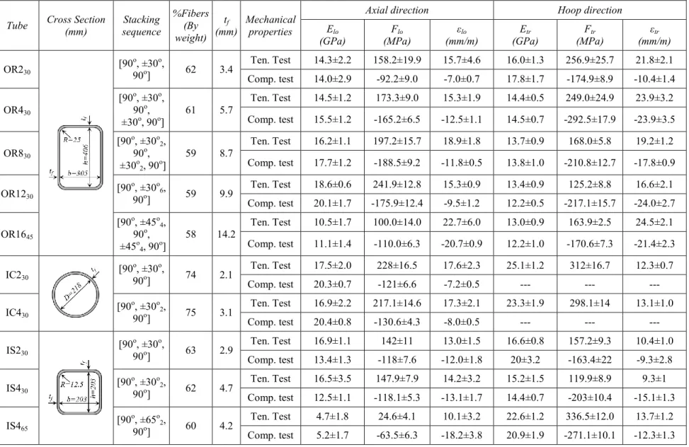
Table 3.1 – Configurations and mechanical properties of fabricated filament-wound GFRP tubes ... 57 Table 3.2 – Details of beam specimens ... 58
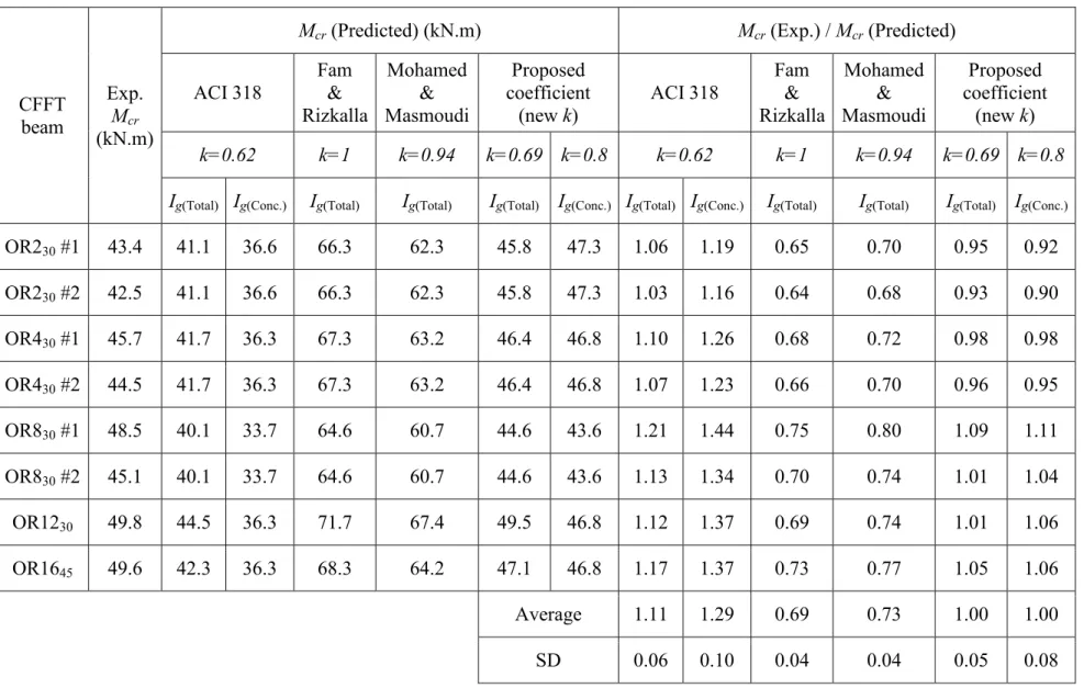
Table 4.1 – Beam specimens and summary of test results ... 109 Table 4.2 – Shear forces in fully-CFFT beams ... 110 Table 4.3 – Details of calculating cracking strength of fully-CFFT beams... 111 Table 4.4 – Experiment versus predicted cracking moment for rectangular CFFT beams .. 112 Table 4.5 – Internal forces and their positions in rectangular CFFT section ... 113 Table 4.6 – Theoretical versus experimental yield moments of rectangular CFFT beams .. 114 Table 4.7 – Theoretical versus experimental ultimate moments of rectangular CFFT beams using unconfined concrete model ... 115 Table 4.8 – Theoretical versus experimental ultimate moments of rectangular CFFT beams using partially confined concrete model ... 115
Table 5.1 – Beam specimens and summary of test results ... 166 Table 5.2 – Shear forces in fully and partially-CFFT beams ... 167 Table 5.3 – Details of calculating cracking strength of partially-CFFT beams ... 168
xxiii
Figure 2.1 – Schematic of pultrusion process [http://mdacomposites.org] ... 33 Figure 2.2 – Schematic of RTM process [http://mdacomposites.org] ... 33 Figure 2.3 – Schematic of VARTM process [http://mdacomposites.org] ... 34 Figure 2.4 – Schematic of compression molding process [http://mdacomposites.org] ... 34 Figure 2.5 – Schematic of filament winding machine [http://mdacomposites.org] ... 35 Figure 2.6 – Resin bath types in filament winding process [http://mdacomposites.org] ... 35 Figure 2.7 – Distribution of composite manufacturing process wise [Beckwith 2006] ... 36 Figure 2.8 – Composite manufacturing cost by different processes [Taheri 1996] ... 36 Figure 2.9 – Field applications of CFFTs [http://google.com] ... 37 Figure 2.10 – Moment-curvature response and failure modes of B1 and B2 [Fam and
Rizkalla 2002] ... 38 Figure 2.11 – Effect of concrete strength on load-deflection curves [Mohamed and
Masmoudi 2010] ... 38 Figure 2.12 – Effect of FRP tube thickness on load–deflection curves [Mohamed and
Masmoudi 2010] ... 39 Figure 2.13 – Load-deflection response and failure modes of B3 and B4 [Fam and Rizkalla 2002] ... 39 Figure 2.14 – Load-deflection curves for specimens B1 to B7 [Cole and Fam 2006] ... 40 Figure 2.15 – Effect of rebar type on load–deflection curves [Mohamed and Masmoudi 2010] ... 41 Figure 2.16 – Beam test results of Belzer et al. (2013)... 41 Figure 2.17 – Load-deflection behaviour for different beam configurations [Fam and Rizkalla 2002] ... 42 Figure 2.18 – Beam test results of Fam et al. (2005) ... 43 Figure 2.19 – Previous approaches of hybrid composite sections ... 44 Figure 2.20 – Proposed cross-section by Elmahdy et al. (2008) ... 44 Figure 2.21 – Proposed cross-section by Khennane (2010) ... 45 Figure 2.22 – Cross-section examples of DSTB [Idris and Ozbakkaloglu 2014] ... 45
xxiv
Figure 3.2 – Fibers installment in filament winding process ... 59 Figure 3.3 – Fiber laminates structure patterns ... 60 Figure 3.4 – Curing of FRP tubes by applying heat ... 60 Figure 3.5 – Removing the mandrel ... 61 Figure 3.6 – Final Products of GFRP tubes ... 61 Figure 3.7 – Sand coating for GFRP tubes ... 62 Figure 3.8 – Fiber content test (ASTM D3171-09) ... 62 Figure 3.9 – DSC test (ASTM D3418-08) ... 63 Figure 3.10 – Coupons tests and instrumentations ... 64 Figure 3.11 – Coupons tests results of OR1230 and OR1645 in axial direction ... 65
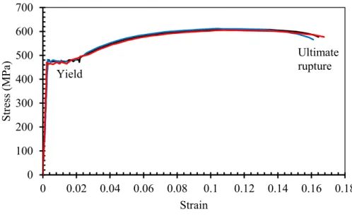
Figure 3.12 – Stress-strain response of steel bar 15M ... 65 Figure 3.13 – Cross section configurations of the tested beams ... 66 Figure 3.14 – Reinforcement cages and tubes assembly ... 66 Figure 3.15 – Details of beam specimens (dimensions are in mm) ... 67 Figure 3.16 – Casting process ... 68 Figure 3.17 – Seven days moisture curing for CFFT beams ... 68 Figure 3.18 – Concrete cylinders tests (ASTM C39-12) ... 69 Figure 3.19 – Typical schematic of test setup and instrumentations (dimensions are in mm) 70 Figure 3.20 – View of beam test setup ... 70 Figure 3.21 – Supports ... 71 Figure 3.22 – Scheme of loading and unloading cycles (rate = 1 mm/min) ... 71 Figure 3.23 – DPs positions to measure deflection and slippage ... 72 Figure 3.24 – LVDTs to measure top and bottom axial strains ... 72 Figure 3.25 – Strain gages on steel bars and inner tubes ... 73 Figure 3.26 – Strain gages on outer tubes ... 73
Figure 4.1 – Moment-slip response of fully-CFFT beams ... 116 Figure 4.2 – Typical steel strains and curvature of fully-CFFT beams ... 116 Figure 4.3 – Shear forces in fully-CFFT beams ... 116
xxv
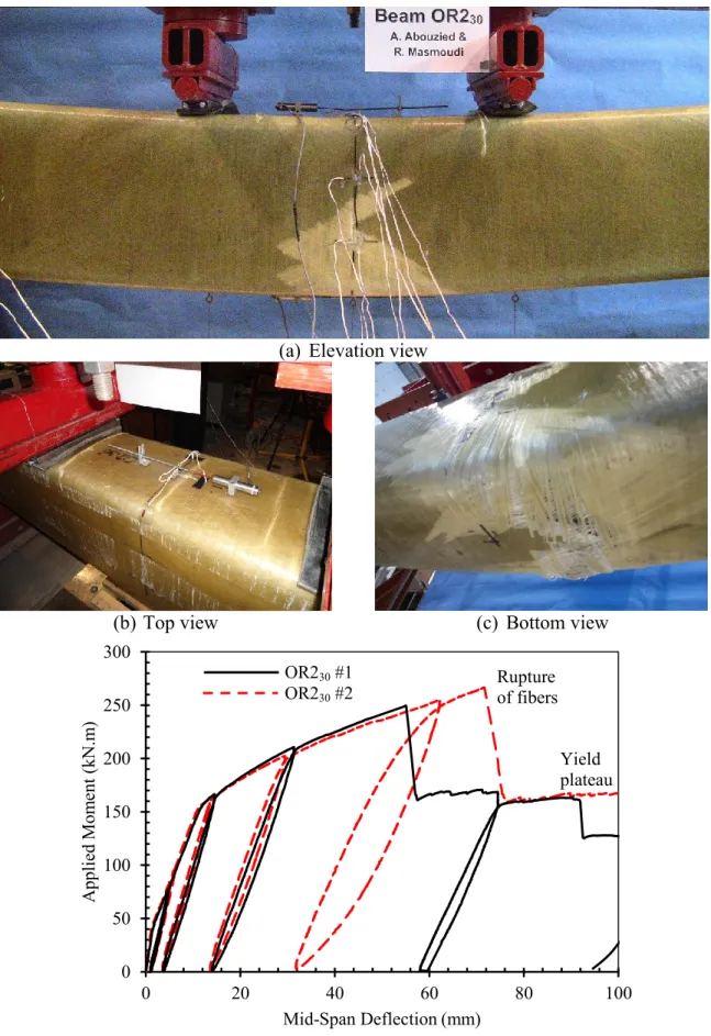
Figure 4.6 – Failure pattern and moment-deflection response of RC beams... 118 Figure 4.7 – Failure pattern and moment-deflection response of fully-CFFT beams OR230 119
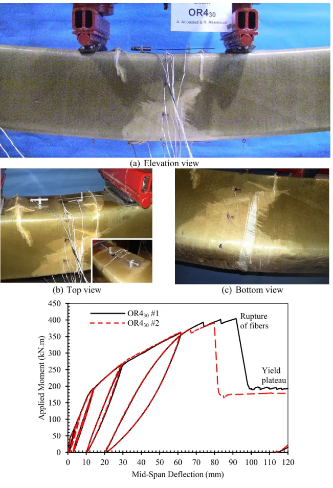
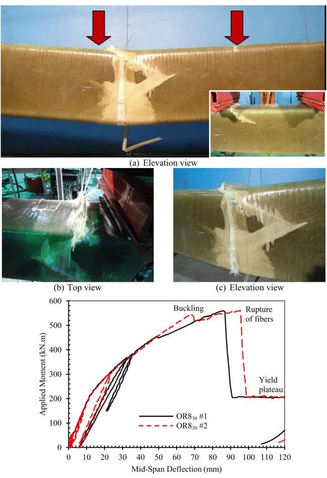
Figure 4.8 – Failure pattern and moment-deflection response of fully-CFFT beams OR430 120
Figure 4.9 – Failure pattern and moment-deflection response of fully-CFFT beams OR830 121
Figure 4.10 – Failure pattern and moment-deflection response of fully-CFFT beam OR1230
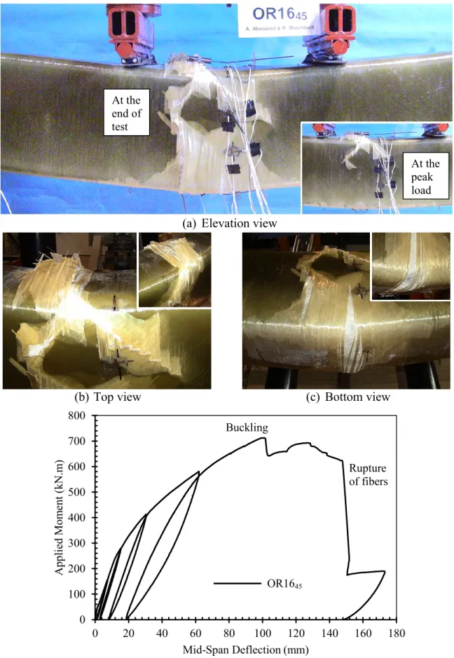
... 122 Figure 4.11 – Failure pattern and moment-deflection response of fully-CFFT beam OR1645
... 123 Figure 4.12 – Moment-deflection response of fully-CFFT beams ... 124 Figure 4.13 – Normalized moment-curvature response of fully-CFFT beams ... 125 Figure 4.14 – Proposed effect of steel reinforcement in fully-CFFT beams ... 125 Figure 4.15 – Coupons tests results of OR1230 and OR1645 in axial direction ... 126
Figure 4.16 – Correlations between Mcr, My, and Mu of fully-CFFT beams ... 127
Figure 4.17 – Proposed analytical model ... 128 Figure 4.18 – Proposed model for steel ... 128 Figure 4.19 – Proposed model for FRP tube... 129 Figure 4.20 – Proposed model for concrete ... 129 Figure 4.21 – Effect of concrete confinement model ... 130 Figure 4.22 – Axial and transverse strains at the top face of the FRP tube in CFFT beams 131 Figure 4.23 – Theoretical versus experimental moments of CFFT beams ... 131 Figure 4.24 – Predicted versus experimental moment-strain response of CFFT beam OR230
... 132 Figure 4.25 – Predicted versus experimental neutral axis depth of CFFT beam OR230 ... 132
Figure 4.26 – Predicted versus experimental moment-curvature response of CFFT beam OR230 (Model with partially confined concrete) ... 133
Figure 4.27 – Predicted versus experimental moment-deflection response of CFFT beam OR230 (Model with partially confined concrete) ... 133
Figure 4.28 – Predicted versus experimental moment-strain response of CFFT beam OR430
xxvi
OR430 (Model with partially confined concrete) ... 135
Figure 4.31 – Predicted versus experimental moment-deflection response of CFFT beam OR430 (Model with partially confined concrete) ... 135
Figure 4.32 – Predicted versus experimental moment-strain response of CFFT beam OR830
... 136 Figure 4.33 – Predicted versus experimental neutral axis depth of CFFT beam OR830 ... 136
Figure 4.34 – Predicted versus experimental moment-curvature response of CFFT beam OR830 (Model with partially confined concrete) ... 137
Figure 4.35 – Predicted versus experimental moment-deflection response of CFFT beam OR830 (Model with partially confined concrete) ... 137
Figure 4.36 – Predicted versus experimental moment-strain response of CFFT beam OR1230
... 138 Figure 4.37 – Predicted versus experimental neutral axis depth of CFFT beam OR1230 ... 138
Figure 4.38 – Predicted versus experimental moment-curvature response of CFFT beam OR1230 (Model with partially confined concrete)... 139
Figure 4.39 – Predicted versus experimental moment-deflection response of CFFT beam OR1230 (Model with partially confined concrete)... 139
Figure 4.40 – Effect of steel reinforcement on the flexural behaviour of CFFT beams with thin FRP tubes ... 140 Figure 4.41 – Effect of steel reinforcement on the flexural behaviour of CFFT beams with thick FRP tubes ... 141 Figure 4.42 – Effect of fiber laminates structure on the flexural behaviour of CFFT beams142 Figure 4.43 – Effect of FRP tube thickness on the flexural behaviour of CFFT beams ... 143 Figure 4.44 – Effect of concrete strength on the flexural behaviour of CFFT beams ... 144
Figure 5.1 – Moment-slip response in partially-CFFT beams ... 169 Figure 5.2 – Typical steel strains and curvature of partially-CFFT beams ... 170 Figure 5.3 – Shear forces in partially-CFFT beams ... 170 Figure 5.4 – Failure pattern and moment-deflection response of RC beams... 171
xxvii
30
Figure 5.7 – Failure pattern and moment-deflection response of fully-CFFT beams OR830 174
Figure 5.8 – Failure pattern and moment-deflection response of partially-CFFT beam OR230
-IC430 ... 175
Figure 5.9 – Failure pattern and moment-deflection response of partially-CFFT beam OR430
-IC430 ... 176
Figure 5.10 – Failure pattern and moment-deflection response of partially-CFFT beams OR430-IC230 ... 177
Figure 5.11 – Failure pattern and moment-deflection response of partially-CFFT beams OR830-IC430 ... 178
Figure 5.12 – Failure pattern and moment-deflection response of partially-CFFT beams OR430-IS230 ... 179
Figure 5.13 – Failure pattern and moment-deflection response of partially-CFFT beams OR430-IS430 ... 180
Figure 5.14 – Failure pattern and moment-deflection response of partially-CFFT beams OR430-IS465 ... 181
Figure 5.15 – Failure pattern and moment-deflection response of partially-CFFT beams OR830-IS430 ... 182
Figure 5.16 – Moment-deflection response of partially-CFFT beams with circular voids .. 183 Figure 5.17 – Correlations between Mcr, My, and Mu of partially-CFFT beams with circular
voids ... 184 Figure 5.18 – Effect of the inner tube thickness in partially-CFFT beams ... 185 Figure 5.19 – Typical neutral axis location in partially-CFFT beams ... 186 Figure 5.20 – Effect of the inner tube laminates in partially-CFFT beams ... 186 Figure 5.21 – Effect of the inner tube shape in partially-CFFT beams ... 187 Figure 5.22 –Partially-CFFT beams with circular voids versus fully-CFFT beams ... 188 Figure 5.23 – Partially-CFFT beams with square voids versus fully-CFFT beams ... 189 Figure 5.24 – Strains in the FRP tube of OR230 ... 190
Figure 5.25 – Strains in the FRP tubes of OR230-IC430 ... 190
xxviii
Figure 5.29 – Strains in the FRP tubes of OR430-IS230 ... 193
Figure 5.30 – Strains in the FRP tubes of OR430-IS430 ... 194
Figure 5.31 – Strains in the FRP tubes of OR430-IS465 ... 195
Figure 5.32 – Strains in the FRP tube of OR830 ... 196
Figure 5.33 – Strains in the FRP tubes of OR830-IC430 ... 196
Figure 5.34 – Strains in the FRP tubes of OR830-IS430 ... 197
Figure 5.35 – Flexural strength-to-weight ratios of RC beams, fully-CFFT beams, and
partially-CFFT beams with circular voids ... 198 Figure 5.36 – Flexural strength-to-weight ratios of RC beams, fully-CFFT beams, and
partially-CFFT beams with square voids ... 199
Figure 6.1 – Variation of the effective moment of inertia in fully-CFFT beams ... 213 Figure 6.2 – Variation of the effective moment of inertia in partially-CFFT beams ... 213 Figure 6.3 – Variation of the effective moment of inertia due to different steel reinforcement ratios in fully-CFFT beams (from parametric study) ... 214 Figure 6.4 – Correlations between m and ρf nf + ρs ρs ... 215
Figure 6.5 – Correlations between
g e I I and cr a M M in the RC beams ... 215
Figure 6.6 – Correlations between
g e I I and cr a M M
in the fully-CFFT beams OR230 ... 216
Figure 6.7 – Correlations between
g e I I and cr a M M
in the fully-CFFT beams OR430 ... 216
Figure 6.8 – Correlations between
g e I I and cr a M M
in the fully-CFFT beams OR830 ... 217
Figure 6.9 – Correlations between
g e I I and cr a M M
in the fully-CFFT beams OR1230 ... 217
Figure 6.10 – Correlations between
g e I I and cr a M M
xxix
g cr
Figure 6.12 – Correlations between
g e I I and cr a M M
in the partially-CFFT beam OR430-IC430 219
Figure 6.13 – Correlations between
g e I I and cr a M M
in the partially-CFFT beams OR830-IC430
... 219 Figure 6.14 – Correlations between
g e I I and cr a M M
in the partially-CFFT beams OR430-IS430
... 220 Figure 6.15 – Correlations between
g e I I and cr a M M
in the partially-CFFT beams OR830-IS430
... 220
Figure A.1 – Coupons tests results of OR230 ... 245
Figure A.2 – Coupons tests results of OR430 ... 245
Figure A.3 – Coupons tests results of OR830 ... 246
Figure A.4 – Coupons tests results of OR1230 ... 246
Figure A.5 – Coupons tests results of OR1645 ... 247
Figure A.6 – Coupons tests results of IC230 ... 247
Figure A.7 – Coupons tests results of IC430 ... 248
Figure A.8 – Coupons tests results of IS230 ... 248
Figure A.9 – Coupons tests results of IS430 ... 249
Figure A.10 – Coupons tests results of IS465 ... 249
1
CHAPTER 1
INTRODUCTION
1.1 GENERAL
Engineers and scientists are searching for innovative solutions that provide longer life and require less maintenance than conventional materials and systems. One of such innovations is concrete-filled fiber-reinforced polymer (FRP) tubes (CFFTs). The CFFTs are becoming an attractive and alternative system for many special types of structural applications especially those attacked by corrosive environments such as piles, bridge piers, bridge girders, monopoles, and overhead sign structures. The outer FRP tubes provide corrosion resistant elements, lateral and longitudinal reinforcement, lightweight permanent formworks, in addition to confining the inner concrete core. On the other side, the concrete core supports the tube against local buckling in addition to its role in resisting compressive loads.
Extensive research was developed on CFFTs as columns [Mirmiran et al. 1998, 2001; Fam and Rizkalla 2001; Lam and Teng 2003, 2004; Hong and Kim 2004; Zhu at al. 2006; Teng et al. 2007; Ozbakkaloglu and Oehlers 2008a, 2008b; Mohamed and Masmoudi 2008a, 2008b, 2010a; Mohamed et al. 2010; Park et al. 2011; Abouzied et al. 2012b; Abouzied and Masmoudi 2012, 2013; Ozbakkaloglu 2013a, 2013b; Vincent and Ozbakkaloglu 2013; Idris and Ozbakkaloglu 2013; and others], but comparatively limited research was carried out on CFFTs as beams [Mirmiran et al. 2000; Doval et al. 2001; Fam and Rizkalla 2002; Cole and Fam 2006; Fam et al. 2005; Yu et al. 2006; Mohamed and Masmoudi 2010b, Zakaib and Fam 2012; Belzer et al. 2013] and most of them concentrated on the circular section more than the rectangular section. However, the rectangular section has higher moment of inertia than the circular section in beams. Hence, it has higher flexural stiffness to resist the applied loads and deformations. Moreover, the construction and architectural requirements prefer the rectangular section of beams, rather than the circular beams, due to its stability during
2
installation and its workability during connecting to other structural members like slabs and columns. To date, only two studies on the flexural behaviour of rectangular CFFT beams have been reported, Fam et al. 2005 and Belzer et al. 2013, and their tested specimens number are relatively low (three beams for Fam et al. 2015 and four beams for Belzer et al. 2013) and none of them reinforced the rectangular CFFTs with steel rebar. These dissertation studies a large number of CFFT rectangular beams with steel rebar (twenty-two CFFT beams). Therefore, this research extends the literature of rectangular CFFTs and represents another step toward the CFFT technique to be fully implemented in the field of civil engineering structures and to introduce simple design inspired by the North American design codes provisions.
Unlike steel or FRP-RC beams, the steel-reinforced CFFT beams can exhibit superior additional flexural capacities in the post-yielding stage. This is attributed to the confining action of the FRP tube on the concrete core to withstand high strains, the FRP tube reinforcement contribution in the axial direction, and the reinforcement action of the steel bars in their strain hardening status. In most tested circular CFFT beams that failed in compression, the compression failure was predominantly governed by the compression failure of the tube flange under longitudinal compressive stresses where the tensile hoop strains (i.e., confinement effect) was insignificant [AASHTO 2012]. Note that, these observations are based on flexural tests of circular CFFTs without steel reinforcement and more investigations are required to verify that observations on rectangular CFFTs with steel rebar.
Analytical models have been developed to predict the flexural capacity and load-deflection response for the circular CFFTs [Cole and Fam 2006; Fam and Son 2008; Mohamed and Masmoudi 2010b]. These models are based on strain compatibility, internal forces equilibrium, and material constitutive relationships. The forces within the CFFT cross section were calculated by integrating the stress over the area of each individual material. Despite the limited number of tested specimens, these models predict well the flexural behaviour of their circular CFFT beams. Their theoretical analysis depends mainly on a computer-based analysis and requires some sophisticated calculation procedures. These proposed models
3
require also verification and adjustment to be valid for the rectangular CFFT beams, and need to be simplified to be applicable for engineers.
The CFFTs that are completely filled with concrete are not optimal for applications governed by pure bending, because the concrete below the neutral axis is cracked and it contributes slightly to bending resistance and mainly prevents the tube from buckling. As such, the excess weight of the cracked concrete may increase the transportation and installation cost. A number of FRP-concrete hybrid systems have been developed over the years, including both open and closed FRP forms, to reduce the excess weight of the cracked concrete below the neutral axis [Deskovic and Triantafillou 1995; Canning et al.1999; Fam and Rizkalla 2002; Chakrapan 2005; Khennane 2010; Idris and Ozbakkaloglu 2014]. While, limited trials were carried out on filament-wound FRP tubes especially those with rectangular section [Fam et al. 2005].
Fam and Rizkalla (2002) investigated the effect of inner holes by testing circular CFFT beams with outer identical GFRP tubes 168 mm diameter. One beam was totally filled with concrete, one beam had a central hole, and another two beams had similar holes, but they are maintained by concentric and eccentric inner GFRP hollow tubes 89 mm diameter. The results indicated that the strength of the CFFT beam with a central hole was 9% less than that of the fully-CFFT beam. Moreover, providing an inner concentric GFRP hollow tube improved the strength by 7% more than that of the fully beam due to the additional reinforcement. Also, shifting the inner GFRP hollow tube toward the tension side was more effective, where the strength increased by 39% higher than the fully-CFFT beam. Fam et al. (2005) designed a rectangular section, 266×374 mm2, of filament-wound GFRP tube with an inner rectangular air void. The strength of the voided section reached 78% of that completely filled with concrete. The hollow beam did not reach the target strength, because it failed by inward buckling and fracture of the unsupported concrete flange at the compression side. Idris and Ozbakkaloglu (2014) investigated the flexural behaviour of FRP-high strength concrete (HSC)-steel composite beams by testing double-skin tubular beams (DSTBs) with outer GFRP tubes and a central inner hollow steel section (HSS). The main parameters of the study included the cross-sectional shapes of the inner HSS and the external GFRP tube, concrete strength, presence or absence of concrete filling inside the steel tube, and effects of
4
using mechanical connectors to enhance the bond between the steel tube and surrounding concrete. The results indicated that DSTBs exhibit excellent load-deflection behaviour with high inelastic deformations and minimal strength degradations (minor increase of flexural strength after yielding). However, relatively large slippage can occur at the concrete-steel tube interface unless the bond is enhanced by mechanical connectors. Regardless the high flexural strength and stiffness of the DSTBs based on the inner steel tube, the weight and the bond remain critical issues in this design and need further investigations.
In this dissertation, the author tries to get benefit of each advantage of each design in the literature and to merge them together to develop a new design of lightweight partially-CFFT beams. This design contains: (1) Outer rectangular GFRP tubes to increase the sectional moment of inertia, to provide flexural and shear reinforcement, and to protect the inner structural elements (concrete and steel) against corrosion, (2) Inner holes shifted toward the tension zone to increase the compression zone area, (3) The holes were provided by inner hollow GFRP tubes to support and confine the concrete at the compression side and to act as reinforcement, (4) Steel rebar is provided at the tension side to increase the stiffness of the section, and (5) The surfaces of tubes adjacent to the concrete were roughened by sand coating to achieve a full composite action.
1.2 RESEARCH OBJECTIVES
The study aims to generate much needed data and to fill research gaps of the rectangular CFFT beams and to represent another step toward the CFFT technique to be fully implemented in the field of civil engineering structures and to introduce simple design inspired by the North American design codes. The study investigates the flexural capacities of rectangular steel-reinforced CFFT beams fully and partially filled with concrete and their corresponding service deflection through testing wide range of GFRP tubes with different thicknesses and configurations. In addition, this study introduces a new design of lightweight partially-CFFT beams. This design contains an outer rectangular filament-wound GFRP tube with an inner hole provided by inner hollow circular or square filament-wound GFRP tubes shifted toward the tension zone of the cross section. The outer GFRP tube itself provides a stay-in-place form, shear and flexural reinforcement, and protects the embedded concrete and
5
steel reinforcement. The inner tubes were designed to act as flexural reinforcement, to support the concrete core at the compression zone, in addition to reduce the weight of the beam. The space between the tubes is filled with concrete that acts as a compression member and eliminates the buckling of the tubes walls. The CFFT beams are reinforced by longitudinal steel bars at the tension side only to enhance their serviceability by increasing their flexural stiffness. The study is seeking also for that using outer and inner GFRP tubes in addition to steel rebar would make the FRP-concrete-steel composite beam fails gradually with enough warning signs. The combination of FRP and conventional structural materials, steel and concrete, aims to optimize the structural section performance based on their individual distinctive properties.
The objectives of this study have been summarized as follow:
1) Experimentally investigate the effect of fiber laminate structure, thickness, and configuration of the outer and inner filament-wound GFRP tubes on the flexural performance of fully and partially-CFFT beams.
2) Compare the rectangular CFFT beams with conventional RC beams in terms of strength to weight ratio and ductility.
3) Analytically design the reinforced CFFT rectangular beams to predict their flexural capacities (crack, yield, and ultimate moments).
4) Examine the North American codes provisions to evaluate the effective moment of inertia required to calculate the deflection and to propose necessary modifications and assumptions.
1.3 METHODOLOGY
This study relies on a comprehensive experimental program involving twenty-four full-scale beam specimens, 3200 mm long and 305×406 mm2 cross section, which have been tested under a four-point bending setup. These specimens include eight fully-CFFT beams with wide range of tube thickness of 3.4 mm to 14.2 mm, fourteen partially-CFFT beams with different outer and inner GFRP tubes configurations, and two conventional steel-reinforced concrete (RC) beams as control specimens.
6
The research program was conducted in a combined experimental and analytical study to achieve the research objectives through the following aspects:
1) Fabrication of the GFRP tubes by filament-winding process in the Civil Engineering Department at the University of Sherbrooke and carrying out all necessary tests to evaluate the physical and mechanical properties of the fabricated filament-wound GFRP tubes.
2) Fabrication of twenty-four full-scale beam specimens and testing them over a simply supported span under a four-point bending setup.
3) Experimental study was conducted to investigate the flexural performance of the fully and partially-CFFT beams according to the test variables.
4) Analytical study was conducted to predict the flexural capacities and behaviour based on linear strain compatibility and failure patterns.
5) Analytical study was conducted to examine and modify Branson’s equation to predict well the effective moment of inertia and deflection of the reinforced CFFT beams at the pre-yielding stage and the post-yielding stage.
1.4 THESIS OUTLINES
Chapter 1 defines the problem and presents the research significance, objectives of the
research project, and the methodology that was adopted.
Chapter 2 provides a literature review concerning the previous work on the flexural
behaviour of CFFT beams reporting the main factors influencing the flexural performance, and the available models for lightweight beams. It reports also a background of different techniques to manufacture FRP composite tubes.
Chapter 3 describes the experimental work program in details. It presents the test matrix,
used material, fabrication of the GFRP tubes, casting process, test procedure, test setup, and measuring devices.
Chapter 4 presents the experimental results of eight fully-CFFT beams with wide range of
7
the fully-CFFT beams in terms of strength and ductility. The fully-CFFT beams attain flexural strength and ductility 444% and 1432% higher than that of the RC beams, respectively. The results indicate that increasing the tube thickness changes the pattern of failure form tension to compression. Moreover, a strain compatibility/equilibrium model was developed to predict the moment-curvature response of the section. The model addresses the issues of confinement and tension stiffening of concrete. The curvature along the span of the flexural member was integrated to predict the deflection. The analytical results match well the experimental results in terms of moment, deflection, strains, and neutral axis responses. Then, a parametric study was carried out to enrich the experimental data. The contents of this chapter have been submitted to the Journal of Engineering Structures. The paper is titled “Flexural behaviour of rectangular FRP-tubes filled with reinforced concrete: experimental and theoretical studies”.
Chapter 5 presents experimental investigations on the proposed new design of lightweight
partially-CFFT beams addressing the effect of the inner tube thickness, laminates and shape on the flexural performance of partially-CFFT beams. The results indicate superior performance of the proposed design compared to the RC beams. The strength-to-weight ratio of the partially-CFFT beams attained higher values than that of the corresponding fully-CFFT beams. Moreover, the general failure pattern of the partially-fully-CFFT beams was gradual in compression unlike the sudden tension failure of the fully-CFFT beams. The contents of this chapter have been published in two journals. First, a paper titled “Structural Performance of New Fully and Partially Concrete-Filled Rectangular FRP-Tube Beams” has been published in Elsevier Construction and Building Materials Journal. Second, a paper titled “New High-Performance Rectangular FRP-Tube Beams Partially Filled with Concrete” has been accepted in ACI–special publication.
Chapter 6 predicts the deflection of such new design of rectangular CFFT hybrid beams
inspired with Branson’s equation. A new power and assumptions were developed into Branson’s equation to predict well the effective moment of inertia of the section. These assumptions consider the effect of the GFRP tube strength, thickness, configuration, and steel reinforcement. In addition, they predict well the deflection in the pre-yielding and post-yielding stages of the hybrid FRP-concrete-steel CFFT rectangular beams. The contents of
8
this chapter have been submitted to the Journal of Structural Engineering ASCE. The paper title is “Effective moment of inertia of rectangular FRP-tube beams fully or partially filled with reinforced concrete”.
The last Chapter of the thesis is Chapter 7, which presents general conclusions obtained from the experimental and theoretical results throughout the thesis. In addition, this chapter suggests recommendations for future work.
9
CHAPTER 2
LITERATURE REVIEW
2.1 INTRODUCTION
In recent years, the application of concrete-filled fiber-reinforced polymer (FRP) tubes (CFFTs) has been used for different structural applications. The most highly developed application to date is the use of CFFTs as pier column and as fender piles in marine structures. The FRP tube provides lightweight structural component, permanent formwork, non-corrosive characteristics, and saving of construction time and effort. Moreover, it provides axial and lateral reinforcement and confinement for the concrete core. On the other side, the concrete core provides support for the tube against buckling in addition to its role to resist the compressive loads. Extensive research was carried out on CFFTs as columns [Mirmiran et al. 1998, 2001; Fam and Rizkalla 2001; Lam and Teng 2003, 2004; Hong and Kim 2004; Zhu at al. 2006; Teng et al. 2007; Ozbakkaloglu and Oehlers 2008a, 2008b; Mohamed and Masmoudi 2008a, 2008b, 2010a; Mohamed et al. 2010; Park et al. 2011; Abouzied et al. 2012b; Abouzied and Masmoudi 2012, 2013; Ozbakkaloglu 2013a, 2013b; Vincent and Ozbakkaloglu 2013; Idris and Ozbakkaloglu 2013; and others], but comparatively limited research was carried out on CFFTs as beams [Mirmiran et al. 2000; Doval et al. 2001; Fam and Rizkalla 2002; Cole and Fam 2006; Mohamed and Masmoudi 2010b, Fam et al. 2005; Yu et al. 2006; Zakaib and Fam 2012; Belzer et al. 2013]. These studies concentrated extensively on the circular section more than the rectangular ones. However, the rectangular section should behave more effective than the circular one in bending. Since concrete has low tensile strength compared to its high compressive strength, it is completely cracked below the neutral axis in the section under flexure. Then, the role of cracked part is limited to support the tube walls against buckling. Since this heavy weight increases the cost of building construction and transportation, many researchers tried to design beam sections with inner voids to reduce the undesired excessive weight of the beams.
10
The high performance of FRP composites especially the filament-wound tubes encourages researchers to use them with conventional materials like steel and concrete to produce lightweight composite sections for beams. This chapter introduces description of the FRP composites materials and manufacturing processes, and a literature review of previous work on CFFTs as beams. Finally, it presents previous trials to make lightweight beams using the FRP composites.
2.2 FRP COMPOSITE MATERIALS
Fiber-reinforced polymer (FRP) composites consist mainly of fibers and resin matrix. Fibers, which are the main load-carrying component, are bonded together with a resin matrix. The matrix not only coats the fibers and protects them from mechanical abrasion, but also transfers stresses between the fibers. Moreover, it transfers inter-laminar and in-plane shear in the composite, and provides lateral support to fibers against buckling when subjected to compressive loads. Additives and fillers may be added for curing or enhancing mechanical and/or physical properties. The use of FRP composite material was pioneered by the aerospace industry in the 1940s, primarily because of its many desirable properties, such as high performance, high strength-to-weight and high stiffness-to-weight ratios, high-energy absorption, and outstanding corrosion and fatigue damage resistance. Now, its use is increasing for civil engineering infrastructure such as buildings and bridges. Table 2.1 indicates the physical and mechanical properties of the most used fibers and resins compared to conventional steel and concrete materials.
2.2.1 Fibers
There are three important categories of fibers: glass, carbon and aramid fibers. Presently, glass fibers are used widely across all industries, although carbon fiber and aramid fiber composites are mostly found in aerospace, automotive and sporting goods equipments [Chakrapan 2005].
11 2.2.1.1 Glass Fibers
Glass fiber or fiberglass is a material made from extremely fine fibers of glass, and it is the largest reinforcement measured in sales. Glass fiber was invented in 1938 by Russell Games Slayter of Owens-Corning as a material to be used as insulation. Ever since then, glass fiber has become widely used as insulation and composite reinforcement material. Based on the composition and the application, glass fibers can be classified in several types. The most commonly used glass fiber type for composite applications is E-glass (electrical glass) and S-glass (structural or high-strength S-glass). E-S-glass has good mechanical properties and high electrical insulation. S-glass is also used in composite materials where high tensile strength is desired, however, this material comes at a much higher cost. Glass fibers are excellent thermal and electrical insulators and are the most inexpensive of the high-performance fibers. Hence, their extensive use is in buildings and the electric power industry as insulation materials.
2.2.1.2 Carbon Fibers
Carbon fibers are used in structural engineering applications today in FRP strengthening sheets, strips, and fabrics, and in FRP pre-stressing tendons. Carbon fiber is a solid semi crystalline organic material consisting of atomic level of planar two-dimensional arrays of carbon atoms. Due to their two dimensional atomic structure, carbon fibers are considered to be orthotropic, having different properties in the longitudinal direction of the atomic array than in the transverse direction. The longitudinal axis of the fiber is parallel to the graphitic planes and gives the fiber its high longitudinal modulus and strength. Carbon fibers are very durable and perform very well in hot and moist environments and when subjected to fatigue loads. They do not absorb moisture. They have a negative or very low coefficient of thermal expansion in their longitudinal direction, giving them excellent dimensional stability. They are, however, thermally and electrically conductive. Compared with glass fibers, carbon fibers have lower density but higher tensile strength and elastic modulus. These properties make carbon fiber an ideal reinforcement for composite materials used in aircraft components, high-performance vehicles, sporting equipment, wind generator blades, and other high performance applications.
12 2.2.1.3 Aramid Fibers
Aramid fibers were used to produce the first generation of FRP pre-stressing tendons in the 1980s in Europe and Japan. However, few manufacturers still produce aramid FRP reinforcing bars or tendons. Aramid fibers consist of aromatic polyamide molecular chains. They were first developed, and patented, by DuPont in 1965 under the trade name Kevlar. A combination of their relatively high price, difficulty in processing, high moisture absorption, low melting temperatures, and relatively poor compressive properties have made them less attractive for FRP parts for structural engineering applications. Their advantages include extremely high tenacity and toughness, and consequently they are used in many industrial products either in bare fabric form or as reinforcements for FRP composites where energy absorption is required. Moreover, they are the lightest of the high performance fibers.
2.2.2 Polymer Resins
There are two types of polymeric matrices widely used for FRP composites; namely, thermoplastic and thermosetting. Thermoplastic polymers are made from molecules in a linear structural form. These are held in place by weak secondary bonds, which can be destroyed by heat or pressure. After cooling, these matrices gain a solid shape. Although it can degrade their mechanical properties, thermoplastic polymers can be reshaped by heating as many times as necessary. Thermosetting polymers are used more often than thermoplastic. They are low molecular-weight liquids with very low viscosity, and their molecules are joined together by chemical cross-links. Hence, they form a rigid three-dimensional structure that once set, cannot be reshaped by applying heat or pressure. Thermosetting polymers are processed in a liquid state to obtain good wet-out of fibers. These materials have good thermal stability, chemical resistance, and undergo low creep and stress relaxation. However, these polymers have relatively low strain to failure, resulting in low impact strength. Two major disadvantages are their short shelf life and long manufacturing time. Some commonly used thermosetting polymers are polyesters, vinyl esters and epoxies [Chakrapan 2005].
13 2.2.2.1 Polyester Resin
Polyester resin is widely used to make pultruded FRP profiles for use in structural engineering. It is also used to make some FRP rebar. When greater corrosion resistance is desired in FRP parts, higher-priced vinyl ester resins are generally recommended, although the corrosion resistance of some polyester resins may be as good as that of vinyl ester resins. Polyester resins can also be used for FRP strengthening for structures. However, epoxy resins are preferred at this time for FRP strengthening applications because of their adhesive properties, low shrinkage, and environmental durability.
2.2.2.2 Epoxy Resin
Epoxy resins are used in many FRP products for structural engineering applications. Most carbon fiber-reinforced pre-cured FRP strips for structural strengthening are made with epoxy resins. In addition, epoxy resin adhesives are used to bond pre-cured FRP strips to concrete (and other materials) in the FRP strengthening process. Epoxy resins are also used extensively in FRP strengthening applications, because, the epoxy resin is applied to dry fiber sheets or fabrics in the field, and then it is cured in situ acting as both the matrix for the FRP composite and as the adhesive to attach the FRP composite to the substrate. Epoxy resins have also been used to manufacture FRP tendons for pre-stressing concrete and FRP stay cables for bridges. They are not used extensively to produce larger FRP profiles, due to their higher costs and the difficulty entailed in processing large pultruded FRP parts.
2.2.2.3 Vinyl Ester Resin
In the last twenty years, vinyl ester resins have become attractive polymer resins for FRP products for structural engineering due to their good properties especially their corrosion resistance and their ease of processing. Today, vinyl ester resins are used widely to make the majority of FRP rebar sold in the world and FRP pultruded profiles. Most manufacturers of pultruded profiles make profiles of identical shape in both polyester and vinyl ester resin series. Vinyl ester resins have also been used to make FRP strengthening strips and FRP rods for near-surface-mounting applications. They are generally replacing polyester resins in FRP
14
products in structural engineering due to their superior environmental durability in alkaline environments.
2.2.3 Fillers
Fillers are used in polymers for a variety of reasons, namely to reduce cost, improve processing, control density, thermal conductivity, thermal expansion, electrical properties, magnetic properties, flame retard, and to improve mechanical properties. Each filler type has different properties depending on its particle size, shape and surface chemistry. In general, the fillers can change the performance of polymer composites by changing the color, viscosity, barrier properties, curing rate, electrical and thermal properties, surface finish, shrinkage, etc.
2.3 FRP COMPOSITE MANUFACTURING PROCESSES
The earliest method of making composites was by manual layup, where each layer of the composites is put manually one above the other to produce the final layout. This consumes much time and needs a lot of skilled labor. This method was made easier using prepregs, which are fibers pre-impregnated with resin. Major advantages of the manual set up are that it has high versatility, but the accuracy is dependent on the skill of the worker and can yield goods with high volume fractions. Its major disadvantages are that it is slow, yields low production rates and there are health and safety issues, such as physical contact with the resin and its fumes [Taheri 1996]. Due to the development in manufacturing technology, there are many ways of making composites. Even though each technique is different, but they all have the following goals [http://mdacomposites.org]:
1) Arrange fibers in the desired orientation and stacking sequence. This ensures the appropriate fiber orientation, and specifies the amount of fiber in each layer of the composite, so it governs the strength and stiffness of the composite.
2) Ensure adequate wetting of fibers. Adequate wetting of the fibers is important to allow the right amount of resin in between the fibers to have an appropriate fiber-resin ratio. This is also crucial to the strength and stiffness of the composite.
![Figure 2.12 – Effect of FRP tube thickness on load–deflection curves [Mohamed and Masmoudi 2010]](https://thumb-eu.123doks.com/thumbv2/123doknet/3344172.96534/71.918.243.697.173.481/figure-effect-frp-thickness-deflection-curves-mohamed-masmoudi.webp)