3-Dimensional Autostereoscopic Displays with 4K Televisions
by Emily M. Van Belleghem S.B., EECS M.I.T., 2017
Submitted to the
Department of Electrical Engineering and Computer Science in Partial Fulfillment of the Requirements for the Degree of Master of Engineering in Electrical Engineering and Computer Science
at the
Massachusetts Institute of Technology February 2018
© 2018 Massachusetts Institute of Technology. All rights reserved.
Author: _______________________________________________________________________
Department of Electrical Engineering and Computer Science
December 15, 2017 Certified by: _______________________________________________________________________
Dr. V. Michael Bove Thesis Supervisor
December 15, 2017 Accepted by: _______________________________________________________________________
Dr. Christopher J. Terman, Chairman, Masters of Engineering Thesis Committee
3-Dimensional Autostereoscopic Displays with 4K Televisions by Emily M. Van Belleghem
Advised by Dr. V. Michael Bove
Submitted to the Department of Electrical Engineering and Computer Science December 15th, 2017
In Partial Fulfillment of the Requirements for the Degree of Master of Engineering in Electrical Engineering and Computer Science
ABSTRACT
This thesis report presents the research conducted over the course of Fall 2016 through Fall 2017 in regards to 3-Dimensional autostereoscopic light fields. It includes work from a senior project called 6.UAP and a Masters of Engineering thesis called the MEng. In the 6.UAP senior project, combination methods for autostereoscopic 3D displays on high definition screens were explored by integrating a Pepper’s Ghost effect (using a trapezoidal prism) with 3D integral imaging (using a lenticular array). In the MEng thesis the complexity of the illusion was increased by utilizing a cone in place of a trapezoidal prism, and a radial parallax barrier in place of a lenticular array. This created a light field with a field of view of about 40 degrees and appeared 3D when perspective was shifted from left to right. The results of this project proved 3D autostereoscopic displays with radial parallax barriers were possible and merit future work in the area of radial lenticular arrays and parallax barriers.
3
Acknowledgements
Foremost, I would like to express my sincere gratitude to my advisor Dr. V. Michael Bove. The completion of this Master Thesis could not have been possible without his motivation, advice, and expertise.
I would also like to thank Dan Novy for his extraordinary support and insight in this thesis process. His patience and guidance were essential to the findings of this thesis.
Last but not least, I would like to thank my family: my parents Audrey and Mark Van Belleghem, and my siblings Sarah and Kent Van Belleghem. Without you, none of this would be possible.
4
Contents
Abstract 2 Acknowledgements 3 List of Figures 6 1 General Information 8 1.1 Thesis Information . . . 8 2 Introduction 9 2.1 Illusions Over Centuries . . . 92.2 The Push Towards Augmented Reality . . . 10
2.3 Current Popular Augmented Reality Displays . . . 10
2.4 Thesis Statement . . . 11
3 General Background Research 12 3.1 The Pepper’s Ghost Illusion . . . 12
3.1.1 Pepper’s Ghost: Related Work . . . 12
3.2 Anamorphic Images . . . 13
3.3 Integral Photography and Lenticular Rendering . . . 14
3.4 Parallax Barriers . . . 16
3.4.1 Dynamic Parallax Barrier: Related Work . . . 17
4 6.UAP Project 18 4.1 6.UAP Methods . . . 18
5
4.1.2 Writing the Lenticular Array Renderer . . . 19
4.1.3 Creating the Pepper’s Ghost Display . . . 21
4.2 Preliminary Results and Discussion from 6.UAP Project . . . 23
5 Master’s Thesis 26 5.1 MEng Methods . . . 26
5.1.1 First Attempts . . . 26
5.1.2 Parallax Barrier Creation . . . 27
5.1.3 Generating images . . . 31
5.1.4 The Cone . . . 32
5.1.5 Rendering and Warp . . . 34
5.1.6 Animation . . . 35 5.2 Results . . . 36 6 Future Applications 42 6.1 Further Testing . . . 42 6.2 Implications . . . 42 7 Appendix A 44 7.1 Software . . . 44 8 References 53
6
List of Figures
3.1 An Illustration of a Pepper’s Ghost illusion in a theater. Burdekin, 2015 [4]. . . . 13
3.2 A simple Pepper’s Ghost illusion created with an iPhone, a piece of transparency, and tape. Shaw [24]. . . 13
3.3 The Ambassadors by Hans Holbein as viewed straight on (left) and from the correct perspective to view the skull (right), Frantz [6]. . . 14
3.4 Evolution of Realism, by Jonty Hurwitz [9]. . . 15
3.5 The first documented drawing of a parallax barrier, created by Bertheir in 1896 [3]. . . 16
3.6 Setup of a traditional parallax barrier [22]. . . 17
4.1 A up-close depiction of a piece of a lenticular sheet with cylindrical lens width p, and height D. Xie, 2011 [28]. . . 19
4.2 A birds eye and sideways view of a lenticular array with a blue and red lined image underneath it. Wikiwand, 2016 [14] . . . 20
4.3 A visual representation of the Law of Reflection, Fitzpatrick [5]. . . 21
4.4 A visual representation of the Fresnel equations [7]. . . 22
4.5 A model of the 6.UAP project system. . . 23
4.6 The input images to the lenticular renderer and the final output image beside it. The rendered image is specific for a Macbook Pro 15” retina screen and a 60 lens per inch lenticular array. . . 24
4.7 A comparison of d’Hubert lenticular images (left) and 6.UAP generated image (right). Patryk [11] . . . 24
List of Figures 7 4.8 A promising final resulting 3-Dimensional autostereoscopic display with a
com-bination method of Pepper’s Ghost and lenticular imaging on a 4K monitor. . . 25
5.1 Figure of translation from rectangular to polar coordinates [22]. . . 29
5.2 Example of a radial parallax barrier. . . 29
5.3 Radial Parallax Barrier with radius indicator. . . 30
5.4 Process of Images autogenerated by a script written in Unity . . . 31
5.5 A single view of a brightly light object in the Unity scene. . . 32
5.6 A cone created from reflective mylar with a 45 degree angle edge. . . 33
5.7 Set up for the Pepper’s Ghost illusion with multiple degrees, including a cone as an optic. . . 33
5.8 Rendered image before warp. . . 34
5.9 An anamorphosis of a rectangular grid using the described formulas (left) and its corresponding results with the mirrored cylinder [17]. . . 35
5.10 Warped image using Bezier curves. . . 36
5.11 Final warped image using a polar transform. . . 36
5.12 Final results, front view 1. . . 37
5.13 Final results, font view 2. . . 38
5.14 Final results, side view 1. . . 39
5.15 Final results, side view 2. . . 40
8
Chapter 1
General Information
1.1 Thesis Information
This proposal outlines an Electrical Engineering and Computer Science (Course VI) Master of Engineering (MEng) thesis under Dr. Michael Bove of the Object-Based Media Group at the MIT Media Lab. This thesis includes relevant work initiated in Fall semester of 2016 during my Undergraduate senior (4th) year 6.UAP project. Master thesis work was initiated in the MIT Spring semester of 2017 and continued through fall semester of 2017. The project involves writing lenticular renderers and creating optics for optimal 3D image performance on high resolution screens such as 4K televisions.
9
Chapter 2
Introduction
2.1 Illusions Over Centuries
Images are a key component of storytelling and explanations. Twenty thousand years ago, some of our earliest ancestors used the flickering light of a fire to animate cave paintings to instruct and entertain younger generations [30]. As time progressed, human’s abilities to demonstrate through art evolved alongside the tools that were invented to create it. From the Egyptian invention of Papyrus in 3000 B.C.E. [18] to Andy Warhol’s experiments on digital art in 1985 [8], expression has grown alongside the technological innovations of the current time. Illusions themselves follow this same trend: inciting a sense of curiosity and wonder while also constantly updating in complexity with the most current breakthroughs. Many of the most famous magicians knew that the best way to keep their audience on edge was to have the most perplexing tricks, thus encouraging them to keep up with the latest in technology to fool their audience. Both artists and illusionists alike knew that although a picture may be worth one thousand words a three dimensional image could be worth even more.
Scientists have explored methods of creating light field illusions for centuries, and in fact have predicted how to create these illusions even before the technology for them had arrived [16]. Now there are many established techniques to mimic a 3D image, including Pepper’s Ghost displays and lenticular photography; however, these methods are rarely combined with one another and have not seen much innovation since their creation. Combinations of these techniques are not preferred because iteratively bending light to a desired angle is non-trivial, and writing renderers for multiple optics takes meticulous testing and patience. Furthermore,
10 Chapter 2. Introduction most current 3-Dimensional illusions are created using lower resolution screens versus 4K or 8K television screens. These illusions are difficult to replicate in high resolution because higher pixel densities add computational cost, financial cost, and the need for accuracy in assembling the physical display setup.
2.2 The Push Towards Augmented Reality
Within the past several years virtual space applications have exploded across the industry with every large scale tech conglomerate working on the latest augmented and virtual reality solutions. With Forbes magazine predicting the Augmented Reality (AR) and Virtual Reality (VR) headset market alone to hit 80 million dollars by the year 2021 [13], it is no surprise that companies are pouring money into production of VR and AR applications. Current computer scientists have been excited by all the potential projects this field will offer, including medical, educational, and entertainment applications. AR specifically has captured the eye of many technology skeptics due to it’s variability and appeal to everyday uses. It also seems especially alluring for it’s reduced eye strain as compared to VR. Regardless of whether one prefers AR to VR, it is becoming very clear that 3-Dimensional imaging will be the way of the future.
2.3 Current Popular Augmented Reality Displays
The definition of Augmented Reality is fairly broad and should be noted. Merriam-Webster officially defines augmented reality as ”an enhanced version of reality created by the use of technology to overlay digital information on an image of something being viewed through a device” [2]. More generally, it is any digital figure that is interactively overlaid on top of our perception of physical reality. Some examples of current AR displays include Heads Up Displays (HUDs) on automobiles and aircrafts, tablets, phones, and other handheld device applications, eyeglasses, and of course headsets. There is also research being done in new types of devices including contact lenses at Google [26] and neurosynthetic hallucinations at the MIT Media Lab [21]. Augmented reality displays that are more easily accessible to the public have applications with a much larger impact on society than those that are still currently
2.4. Thesis Statement 11 in the lab. For example, it was the accessibility of the iPhone and other smartphones that led to the world wide phenomenon of young adults playing a popular AR game called Pokemon GO in 2016 [15], helping spur the viral movement of AR itself.
In hopes of increasing accessibility to public audiences, this research aimed to present a relatively inexpensive 3-Dimensional convincing augmented reality illusion using multiple established techniques simultaneously on a high resolution screen.
2.4 Thesis Statement
The purpose of this thesis is to create an optical illusion which appears as a 3-Dimensional autostereoscopic image using a 4K TV, a large radial parallax barrier, and an inverted cone made of reflective mylar to act as an optical device. This illusion will appear as a light field above the 4K monitor and have a sense of motion parallax (viewpoint changes as the user shifts viewing position horizontally), potentially all the way to 360-degree rotation.
12
Chapter 3
General Background Research
3.1 The Pepper’s Ghost Illusion
The Pepper’s Ghost illusion was first suggested by Henry Dircks in 1858 and was later mod-ified by Professor John Pepper 1862 to derive its modern form known today [4]. The effect is accomplished by angling a piece of glass (or a half silvered mirror) at a 45 degree angle to the viewer with a lit hidden object below it. Light reflects off the angled glass and gives the illusion of a glowing object behind the glass at the same distance the actual object is below it. This phenomenon is further explained by Figure 3.1 below from Pepper’s Ghost at the Opera in Theater Notebook Volume 69, page 153 [4]. In the original Pepper’s Ghost illusion, a 3D object (a concealed actor) was often used in theaters. However, the set up typically used in current illusions involves a 2D video display to create a 2D image. The display was originally intended for a theater stage performance where an actor portraying a ghost would perform hidden, while his reflection would haunt another actor that was on stage.
3.1.1 Pepper’s Ghost: Related Work
Since the Pepper’s Ghost is an illusion that has stood the test of time, there have been many variations through the years that have sprouted from it’s original formula. After the invention of digital displays, a Pepper’s Ghost illusion could be created from the light of a monitor versus bouncing off of an actual physical object. Currently the most simple and widely popular way to create a Pepper’s Ghost is one made with an Apple iPhone or iPad and a piece of plastic transparency. By following an easy ”how-to” guide like the one written on Ideate’s website,
3.2. Anamorphic Images 13
FIGURE3.1: An Illustration of a Pepper’s Ghost illusion in a theater. Burdekin, 2015 [4].
users can create their own Pepper’s Ghost at home with only a plastic taped frustum and their phone [24]. This is an inexpensive and simple way to create a 2D light field within minutes; shown in Figure 3.2.
FIGURE3.2: A simple Pepper’s Ghost illusion created with an iPhone, a piece of
transparency, and tape. Shaw [24].
3.2 Anamorphic Images
Anamorphosis can be more formally defined as ”a distorted projection or perspective; espe-cially an image distorted in such a way that it becomes visible only when viewed in a special manner” [1]. The first anamorphic piece of art was created by Leonardo Da Vinci in 1485, how-ever anamorphosis was not popularized until the 15th and 16th centuries [6]. One of the most famous pieces of anamorphic art from this time period was created in 1533 by Hans Holbein
14 Chapter 3. General Background Research (shown in Figure 3.3) entitled The Ambassadors. The object in the foreground, if viewed from the correct angle, would appear as a skull [6]. Anamorphosis now is very popular in both
FIGURE3.3: The Ambassadors by Hans Holbein as viewed straight on (left) and
from the correct perspective to view the skull (right), Frantz [6].
modern and street art. Current artists enjoy toying with perspective in hyperrealistic surrealist scenes. One of the most well known anamorphic sculptors today is named Jonty Hurwitz. His work typically involves stainless steel and a mirrored cylinder, relying on the reflection to reveal the intended image as shown in Figure 3.4.
3.3 Integral Photography and Lenticular Rendering
Integral imaging and photography was created by Professor Gabriel Lippmann and was re-ported as early as 1911 [10]. It is an autostereoscopic and multiscopic technique of creating 3-Dimensional images from a series of photographs. The effect is accomplished without re-quiring the user to wear any optical device, such as 3D glasses, by relying on the user’s per-spective to display the correct corresponding image. This phenomenon and the related math are explained by Okoshi in his book Three-Dimensional Imaging Techniques, and will be further used to derive the methodology of the MEng project (explained in Chapter 5).
3.3. Integral Photography and Lenticular Rendering 15
FIGURE3.4: Evolution of Realism, by Jonty Hurwitz [9].
and parallax barriers. For the 6.UAP project a lenticular sheet was used, however for the MEng thesis a radial parallax barrier was used to create the 3D effect. Both filter which views a user sees to give the effect of depth perception, however the lenticular sheet is far preferred to a parallax barrier for several reasons.
Firstly, rather than utilizing all of the light emitted from a screen for an illusion like a lenticular, a parallax barrier blocks half of it with black bars. Because of this, the final output is typically striped and dim. The parallax barrier also requires a distance between the barrier and integral image behind it in order for it to work correctly. This is not optimal for illusions with size restrictions and also causes extra time to calculate setup and careful placement, whereas a lenticular can be bound to the integral image without any extra space and careful calculation. The lenticular is also anchored since it is glued together, so the risk of the illusion breaking is far less compared to the parallax barrier that needs to be carefully secured in place and may be bumped over time.
16 Chapter 3. General Background Research
3.4 Parallax Barriers
The concept for a parallax barrier was first created by Auguste Berthier, a Frenchman who published an article on stereoscopic images in 1896 [3]. His initial concept, shown in Figure 3.5, shows a one dimensional parallax barrier that uses the same concepts as the ones used today. The mathematics of a traditional parallax barrier can be best described in Okoshi’s
Three-FIGURE 3.5: The first documented drawing of a parallax barrier, created by
Bertheir in 1896 [3].
dimensional Imaging Techniques. In Figure 5.2 taken from Towards a Common Framework for Parallax Barrier and Holographic 3D Display [16], the setup of a one dimensional parallax barrier is presented. The slit width and width of the spacing between slits are identical, and is calculated through using the pixel pitch of the monitor p. Where the number of desired views for the barrier is k, the slit width is calculated as kp. The distance between the parallax barrier and the pixel array, d, is given by [29]:
d= zpnp
3.4. Parallax Barriers 17
FIGURE3.6: Setup of a traditional parallax barrier [22].
Where e is the approximate distance between the viewers eyes, zpis viewing distance between
the user and the optic, and n is the index of diffraction of the material between the parallax barrier and the screen. Pixel pitch is defined as the width of a single pixel from the display, typically measured in micrometers.
3.4.1 Dynamic Parallax Barrier: Related Work
Recently, there has been quite a bit of research to further the 3D effect beyond the traditional parallax barrier. Dynamic parallax barriers work similarly to their predecessor except they are able to adapt to where the user is positioned and looking at the screen. By using head tracking, the display uses the location of the user’s eyes to render its parallax barrier on a separate OLED screen live for the best possible illusion [20]. This technology is fairly similar to the technology used in the very popular handheld game console, the Nintendo 3DS. Although the 3DS does not use head tracking, it utilizes dynamic parallax barriers in another unique fashion. The 3DS contains a parallax barrier made with a separate LCD display to create a 3D effect on its top screen [25]. Since it’s parallax barrier is created using a second LCD screen, the user can dynamically switch between 2D and 3D modes when playing with the device.
18
Chapter 4
6.UAP Project
For the 6.UAP project, a 2016 Macbook Pro with Retina Display and a lenticular sheet were used for testing, while a 4K monitor with a lenticular sheet was used for final results. The goal was to confirm that the 3D effect of a lenticular image could be transferred through a traditional 2D Pepper’s Ghost setup described in 3.2.1.
4.1 6.UAP Methods
4.1.1 Setting Up the Lenticular Array
In short, integral photography is a way of packaging all the ”3D information” of an object onto a 2D surface. In actuality, the ”3D information” is a special image rendered specifically for use with a fly’s-eye or lenticular lens sheet. To the naked eye, the original rendered image is a blurry and un-intact, sliced up image. The lens sheets are able to filter the views so the human eye will only see at most a couple views at one time. This is extremely useful because the flat image can be displayed on the TV monitor.
It is important to note the difference between lenticular and fly’s-eye arrays as they produce different effects. As Okoshi mentions in Three-Dimensional Imaging Techniques, a true integral image provides both horizontal and vertical parallax. Using a fly’s-eye array provides both dimensions of parallax while the lenticular array provides only one. Although it does not produce a true integral image, a lenticular array was used in the 6.UAP project because of their affordability and abundance in the Object-Based Media Group?s lab space. Since the 6.UAP
4.1. 6.UAP Methods 19 project was a proof of concept, it was only necessary to see the illusion of depth perception in one direction.
The lenticular array, a sheet filled with thousands of miniature cylindrical lenses, is the key to adjusting the sliced image for the human eye. When the lenticular array is placed on top of the backlit image, it filters the light to reform the image in front of the viewer; thus creating a 3-Dimensionally formatted figure with parallax in the horizontal direction. A figure of a lenticular sheet is shown below in Figure 4.1. The lenticular sheet used for testing was
FIGURE4.1: A up-close depiction of a piece of a lenticular sheet with cylindrical lens width p, and height D. Xie, 2011 [28].
measured to have 60 lenses per inch. Most tests were performed on a MacBook Retina display laptop for mobility and because its 226 pixels per inch (ppi) proved similar to the ppis of most 4K screens. With a 60 lens per inch lenticular, and a 226 ppi display, my lenticular renderer could combine around four separate 2D images for four separate views of varying perspectives from left to right. When using the lenticular array the flat underside was placed along the computer screen and the lenses were vertically aligned with the pre-rendered image.
4.1.2 Writing the Lenticular Array Renderer
To ensure that the self written lenticular renderer was accurate, the images used to create the 3-Dimensional effect were taken from an example website on lenticular renderers named Di-togear [11]. A famous lenticular photography artist named Guillaume d’Hubert displayed his work and his process online with sample gifs and final output images. By using the separate
20 Chapter 4. 6.UAP Project frames in the gifs as different view points and then rendering them with the self made pro-gram, it was possible to compare and contrast with the professional final images for accuracy. In his professional lenticular images d’Hubert uses around 40 high definition photographs taken from different angles of a subject to create his final lenticular image [11]. Although his exact process for creating the final render is kept from the reader, one can infer the steps taken to create the finished output. Since his work is also laminated with special lenticular sheets, d’Hubert is able to add several more high definition views within each lens to create a much more convincing illusion. Due to the restrictions of the 6.UAP project needing to be pro-jected from a computer screen and using the lenticular sizes available on hand, the final output render was less sophisticated than d’Hubert’s but fulfilled the purpose of proving whether a 3-Dimensional image could be transferred through a light field. Both the final render of the 6.UAP project and d’Huberts images are shown below within Preliminary Results in figure 4.7.
The lenticular renderer intakes four separate images and outputs one combined image that contains the information of all four. The preface of the renderer is simple and can be more easily explained with Figure 4.2: When testing on the MacBook Pro each cylindrical lens is
FIGURE4.2: A birds eye and sideways view of a lenticular array with a blue and red lined image underneath it. Wikiwand, 2016 [14]
the width of around 4 columns of pixels. The lenticular renderer takes a single row of pixels for each image and places them in order side-by-side underneath a single lens. Iteratively ex-plained, this means for each of the four different views of object, four single of columns pixels
4.1. 6.UAP Methods 21 from each view can fit underneath one column of a lens. Since the number of pixel columns per lens is not exactly 4 (it is 3.7666) the number of columns beneath each lens may vary based upon when the remainders add to the one extra image pixel row. In this way, for each index of all the images, a strip of pixels is added until there are no more. The colored light emitted from the screen is filtered by the lenses at different angles for each pixel, depending on where the user is observing from (as seen in Figure 4.2). The code written for this process can be found in Appendix A.
4.1.3 Creating the Pepper’s Ghost Display
The mathematical explanation for a Pepper’s Ghost display is fairly simple and mostly rely on the law of Reflection demonstrated in Figure 4.3. An incidence ray of light aimed at a mirror at an angle i forms a 90 degree angle combined with the reflected ray’s angle r [5]. This law ap-plies to all reflective materials, however the amount of light conserved in the reflective bounce step depends on how reflective the piece of material is; a mirror reflects all light whereas a piece of glass only reflects very little. For the 6.UAP project, a plastic piece of transparency was used for the reflective surface to achieve a ghost like effect, this was due to it’s availability, along with its light weight and low cost. Later in the Master’s portion of the thesis, a piece of reflective mylar with a higher reflectance was used to conserve as much light as possible.
FIGURE4.3: A visual representation of the Law of Reflection, Fitzpatrick [5].
Exactly how much light is lost and at what angle is best modeled by using the Fresnel equa-tions [19] and Snell’s Law [27] shown below.
22 Chapter 4. 6.UAP Project Fresnel Equations: ts= nn1cos(qi) n2cos(qt) 1cos(qi) +n2cos(qt) (4.1) rs= n 2n1cos(qi) 1cos(qi) +n2cos(qt) (4.2) rp = nn2cos(qi) n1cos(qt) 1cos(qt) +n2cos(qi) (4.3) rs= n 2n1cos(qi) 1cos(qt) +n2cos(qi) (4.4) Snell’s Law: n1sin(qi) =n2sin(qt) (4.5)
FIGURE4.4: A visual representation of the Fresnel equations [7].
A model of the system for the 6.UAP Pepper’s Ghost can be seen in Figure 4.5. Following the Law of Reflectance and the Fresnel equations:
When testing the Pepper’s Ghost display, the rendered image described in 4.5 was dis-played on the 4K monitor and the lenticular array was set directly on top. Since the new
4.2. Preliminary Results and Discussion from 6.UAP Project 23
FIGURE4.5: A model of the 6.UAP project system.
monitor had a ppi of around 163, the pre-rendered image was first adjusted according to the new specs. Since the ppi of the new display was less, only around 3 pixels (2.7166) could fit within each lens of the lenticular. The monitor was laid parallel to the floor, and the lenticular was aligned and image was shifted until the best possible 3D effect was seen. After alignment, an upside down trapezoidal prism (frustum) was placed just below the image so that when viewed at eye-level parallel to the floor a 3D light field was seen. With the frustum creating a 45 degree angle between the monitor and it’s plastic edge, light from the 4K monitor reflected off of the plastic and toward the viewer (parallel to the floor). The physical setup for this Pepper’s Ghost is shown in Figure 5 within Preliminary Results.
4.2 Preliminary Results and Discussion from 6.UAP Project
Figure 4.6 is an example of four input images and the output provided by the lenticular ren-derer from the 6.UAP project. The image here is zoomed in for clarity, but when used with the MacBook it must be shrunk down to the appropriate size for correct viewing.
24 Chapter 4. 6.UAP Project
FIGURE 4.6: The input images to the lenticular renderer and the final output
image beside it. The rendered image is specific for a Macbook Pro 15” retina screen and a 60 lens per inch lenticular array.
Below is a comparison of d’Huberts final lenticular image and the 6.UAP lenticular image.
FIGURE4.7: A comparison of d’Hubert lenticular images (left) and 6.UAP
gen-erated image (right). Patryk [11]
This final output image was then re-rendered for the 4K monitor and shrunk down to the correct size. The final result combining the Pepper’s Ghost illusion and the 3D image from the lenticular array are shown below in Figure 4.8.
4.2. Preliminary Results and Discussion from 6.UAP Project 25
FIGURE4.8: A promising final resulting 3-Dimensional autostereoscopic display
with a combination method of Pepper’s Ghost and lenticular imaging on a 4K monitor.
After seeing promising preliminary results from the 6.UAP project, it was clear that contin-uing with the premise of combining techniques to create 3-Dimensional autostereoscopic light fields would likely hold for more advanced techniques including replacing the trapezoidal op-tic for a cone shaped one. The proof of concept showed that a 3-Dimensional image could be passed through a Pepper’s Ghost display, the light field appeared clear and when the user’s perspective shifts from left to right the image appears 3-Dimensional. Research for the Master Thesis began in Spring of 2017.
26
Chapter 5
Master’s Thesis
5.1 MEng Methods
The Master Thesis, although originally built off of the 6.UAP work, grew over time to include more complications. After some initial experiments, it was clear that the final physical creation would look very different than first anticipated even though the illusion would appear as ex-pected. Outlined below is the process for recreating the final autostereoscopic Pepper’s Ghost illusion which was completed in Fall of 2017.
5.1.1 First Attempts
After finishing the 6.UAP project, the first objective was to turn the 3D image into one that could be projected onto a curved surface such as a cone or bowl. This would allow a 3D au-tostereoscopic image that could potentially cover 360 degrees. To do this, the lenticular would not suffice because of its rigid and straight structure. To work around this, several ideas were attempted including wrapping the lenticular around a cylinder, bending lenticulars, and even considering finding a fly’s eye array instead of a lenticular.
Aiming to still take advantage of the extra sheets of lenticular in the lab, the first idea at-tempted wrapping mirrored mylar around a cylinder and then wrapping the lenticular on top of that. The thought process behind this being that wrapping the lenticular around the cylinder would counteract the need for a radial lenticular. To test this, we used a rendered image with color stripes, alternating between 3 different colors to be filtered by the lenticular. This method worked to a point, shifting left and right while facing the cylinder would give the illusion of
5.1. MEng Methods 27 each color flashing. However the color was faint and once the color stripes were changed to an actual picture all details of the photograph were completely lost in a blur.
The second idea was to bend the lenticular so it was curved in a radial fashion. By using a heat gun and a small piece of lenticular, the plastic was heated until malleable and then hand pulled to form a makeshift radial lenticular. This method was also unsuccessful since the plas-tic was not thick enough to warp uniformly and would buckle at the ends.
The last option considered was to use a fly’s eye lenslet array in place of a lenticular. Since the fly’s eye is no longer a linear array like the lenticular and consists of miniature rounded lenses, it filters images in both the vertical and horizontal directions. The fly’s eye array is much more expensive and would need to be specially ordered. It also would make rendering the image very complex since certain pixels would need to be blacked out so as not to reflect light in the wrong direction. Even though we would be using a fly’s eye, we would be pro-gramming for it so that it acted as just a radial lenticular. Because the fly’s eye would not be used to its full capacity and we expected it to be a very dim illusion due to blacking out pixels, it was decided that the MEng thesis take a different direction.
It was clear that the real piece of equipment that we needed would be a radial lenticu-lar. However, it was known that having a radial lenticular specially made is very expensive, and privately milling one at the lab would not only produce less than favorable results but also remove the availability factor to future users once the project was finished. After careful deliberation, it was decided that a radial parallax barrier would be used in place of a radial lenticular, in hopes that the illusion would still be bright enough to see if placed in a dark setting.
5.1.2 Parallax Barrier Creation
Knowing that lenticular arrays and parallax barriers both used integral imaging, switching from using one to the other was not too difficult. After verifying that a regular parallax barrier worked with the previously rendered 6.UAP images, the next step was changing the linear parallax barrier into a radial one. Adobe Photoshop was used to create a regular parallax barrier which was then warped using an algorithm and printed using a LaserJet printer.
28 Chapter 5. Master’s Thesis The ppi of the 4K monitor was already known to be around 163, it was also known that the smallest number of views that could be fit underneath the previously used lenticular was around 3 for the 4K monitor. However now that the lenticular was no longer being used and the parallax barrier’s stripe width could be controlled, there was no longer a strict number of views to adhere to. In fact, the limiting factor for view count was no longer the monitor ppi or the parallax ppi, but the dpi constraint of the Laser Jet Printer used to print the Parallax Barrier. It was decided that the inner radius of the parallax barrier should be printed with lines as close together as the printer would allow.
To create the parallax barrier in Adobe Photoshop, vertical stripes were added to a blank file. The thickness of the stripes and the distance between them were equivalent but varied for each test. The final parallax barrier with the closest and thinnest lines that the printer was able to print ended up being 7 pixels wide. The parallax barrier originally began as an Adobe Photoshop file the size of the 4K Monitor (3840x2160 pixels) with vertical black lines 7 pixels wide and 7 pixels apart. To test if the radial parallax barrier would work, the ”convert to polar transform” function was utilized to create a makeshift radial parallax barrier. Afterwards it was realized this function was inconsistent and hard to control; when warping the final barrier a different function would need to be used.
For this reason, the vertical striped 7px file was then saved as a png and warped in Unity with a variation of a polar transform. The general mathematical transformation for this is outlined below and in Figure 5.1 where Xpand Ypare the rectangular coordinates and r and q
are polar coordinates [23].
Xp =rcos(q) (5.1) Yp=rsin(q) (5.2) r =qX2 p+Yp2 (5.3) q =tan 1Yp Xp (5.4)
After converting to polar coordinates the warp was adjusted such that the center of the polar warp was located at the top middle of the rendered screen. This resulted in a radial
5.1. MEng Methods 29
FIGURE5.1: Figure of translation from rectangular to polar coordinates [22].
parallax barrier that was printed on a sheet of transparency and appeared similar to that in Figure 5.2. The code for this can be found in Appendix A.
FIGURE5.2: Example of a radial parallax barrier.
Since the Laser Jet printer’s accuracy diminished lower than 7px, a radius was drawn at this mark to ensure the final illusion remained above 7px in resolution. This is shown below in Figure 5.3. The radial parallax barrier was then placed above the 4K monitor using a sheet of clear acrylic raised by a distance d.
To calculate this d, both ends of radial parallax barrier needed to be taken into account. At the tightest end of the barrier, the stripes are optimally positioned for the pixel pitch of the monitor. Knowing the 4K monitor’s pixels per inch to be around 163, the pixel pitch was calculated at 0.155 millimeters. For seven different views to fit within each pixel, the optimum
30 Chapter 5. Master’s Thesis
FIGURE5.3: Radial Parallax Barrier with radius indicator.
slit size of a parallax barrier for this 4K monitor would be 1.085 millimeters. This aperture was the size used for each slit on the inner most radius of the barrier just before the red semi circle indicator in Figure 5.3. At the end of the parallax barrier, the slit width is wider due to the need to warp the display image, however the number of views underneath each slit still remains the same. The maximum slit width was measured at 4 millimeters. Other necessary variables included zp the distance the user stood from the illusion. This was measured from
where a ray of light would hit the mylar cone, at the base of the cone this was taken to be 2.338 meters where at the top of the cone, this was taken to be 2.438 meters because the light needed to travel farther. Along with this, e, the average distance between human eyes was taken to be 63 mm, and n, the average index of refraction for air, was taken to be 1.00.
Calculating d for the smallest radius of the barrier resulted in 5.752 millimeters, while calcu-lating d for the end radius gives d to be 5.998 millimeters. It is important to note, that although the pixel pitch of the monitor seemed to have dynamically shifted from one end of the parallax barrier to the other, the virtual pixel pitch of the light field remains constant. This is proven by the fact that when the user gazes at the cone, straight parallel lines are seen with the width of 7 pixels. Since the the change in d is so minuscule, a d value averaged between the two calculated d’s gave a convincing illusion. By keeping d at one value, we were able to keep the cost of the final display low by eliminating the need to find a gradually bowl shaped piece of acrylic.
5.1. MEng Methods 31
5.1.3 Generating images
The cross-platform game engine Unity was used to simulate a virtual object and generate the views for the final illusion. First the modeled objects to be captured were placed in a virtual 3D scene and brightly lit. Then depending on the public number of cameras specified by the user, the C# script autogenerated cameras in an even spaced ring around the center objects, much like the methodology Okoshi uses in Three Dimensional Imaging Techniques [16]. For example, if 360 cameras were specified, then each camera would be 1 degree apart on the circle. After testing the best distance between cameras for the written parallax barrier was 6 degrees apart with 7 separate views. Upon generation each of the cameras would snap a photo from its corresponding viewing angle and write the picture as a png file to disc. This process is shown in figure 5.4 and the C# code is given in Appendix A.
FIGURE5.4: Process of Images autogenerated by a script written in Unity
After writing the views to a folder (each would look similar to Figure 5.5 but from separate angles) the lenticular renderer would read the seven views specified by the user to generate the rendered image.
32 Chapter 5. Master’s Thesis
FIGURE5.5: A single view of a brightly light object in the Unity scene.
5.1.4 The Cone
The optic chosen for the final Pepper’s Ghost illusion was an inverted cone made of a translu-cent reflective mylar material. The cone was created by using some string, an expo marker and and an X-Acto knife. By holding one end of the string stable in the center of the plastic material, two circles were drawn out with the expo marker, one with a 2.5 inch diameter and one with around a 20 inch diameter. The circles were cut with the X-Acto knife to create a donut shape, then a straight line was cut down from the inner radius to the outer radius. The plastic was then wrapped around itself in a cone fashion until when laid flush with the edge of the cutting board its edge created a 45 degree angle as shown in figure 5.6. Excess plastic was cut away from the top and from over wrapping to prevent extra warping and remove extra weight.
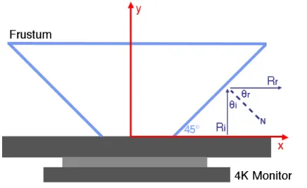
This cone was then used as an optic in the multiple degree Pepper’s Ghost illusion. Since the cone’s edge stood at a 45 degree angle to the 4K monitor just as the frustum in the 6.UAP project did, all of the same laws of optical physics applied, however now the rendered image must account for the curvature of the cone. A model of the setup is shown in figure 5.10. The setup shows that for an incidence ray Riwith an angle a that is projected from the 4K Monitor,
the corresponding reflected ray Rrwill again run parallel to the floor toward the viewers eye as
5.1. MEng Methods 33
FIGURE5.6: A cone created from reflective mylar with a 45 degree angle edge.
FIGURE 5.7: Set up for the Pepper’s Ghost illusion with multiple degrees, in-cluding a cone as an optic.
the z direction. Since the reflective surface was now arched in the z direction versus remaining flat, the final rendered image also needed to be warped to handle the curved geometry.
34 Chapter 5. Master’s Thesis It is important to note that a cone was used in place of a cylinder as an optic for two main reasons. The first reason being that with a cone, there would be more volume to work with for a larger illusion. The transform used to warp the image was written for that of a cylinder, so the projection of the image is for that of a cylinder. However since the volume of a cylinder is contained within the cone, the polar transform for a cylinder worked perfectly well. The second reason for using a cone was that the angle of incidence and reflection could be much better controlled. With a cone angled at 45 degrees it is accepted that the light reflecting off the cone would run parallel to the floor to hit the user’s eye. The 45 degree angle would also catch more light from the display where a 90 degree angle would experience some falloff near the top of the illusion.
5.1.5 Rendering and Warp
After the parallax barrier had been defined (as explained in section 5.1.2), the final output im-age was rendered from the views created in section 5.1.3 using the same rendering method as in the 6.UAP project. This image (shown in Figure 5.8) was then warped to account for the circular curvature of the cone using the same algorithm used to warp the barrier.
5.1. MEng Methods 35 The warping of the final rendered image is very similar to that of anamorphosis done in the art pieces in section 5.1. In The Mathematics behind Anamorphic Art, Rausch explains the trans-formation for a mirrored anamorphic cylinder [17]. The final anamorphic warp was created using a polar coordinate transform with a high definition image, however the initial tests were created with lower resolution images and warped with Bezier curves for proof of concept.
FIGURE5.9: An anamorphosis of a rectangular grid using the described formulas
(left) and its corresponding results with the mirrored cylinder [17].
To test the initial warp of the image, the original render was saved into Unity as a texture map on a plane. The plane was then warped into a half donut shape through the use of Bezier curves. First, a Bezier curve was written for both the inner and outer radius of the cone. Then each horizontal edge of the rectangular image was deformed to match the inner and outer Bezier curves respectively, shown in Figure 5.10. The preliminary images generated from the Bezier curves were perfect for testing as it allowed for easy and fast manipulation, how-ever it was not suitable for a final warp as it was inaccurate. For the final warp, the same polar transform used for the radial parallax barrier was used for high resolution display images. The difference can be seen in Figure 5.11, and the code used for this transform can be found in Apendix A.
5.1.6 Animation
To give the 3D autostereoscopic light field a little more life, animated sequences were rendered and displayed on the cone. To generate the animated sequences, multiple frames of every view
36 Chapter 5. Master’s Thesis
FIGURE5.10: Warped image using Bezier curves.
FIGURE5.11: Final warped image using a polar transform.
used for the rendered image were stored. Then each frame was rendered with its respective views and then sewn back together into a movie which could be looped on the 4K monitor.
5.2 Results
The results of the final Master thesis are shown below in Figures 5.12-5.14. As the view stepped from left to right a parallax was observed in the light field. Results granted around a 40 degree field of view from around 4.5 feet distance from the cone. It was also observed that as the user moved further away, the stripes on the image immediately began to fade until almost barely visible. With further testing, it is believed a wider filed of view can be attained
5.2. Results 37
38 Chapter 5. Master’s Thesis
5.2. Results 39
40 Chapter 5. Master’s Thesis
5.2. Results 41
42
Chapter 6
Future Applications
6.1 Further Testing
After finishing the project, there are still several other potential areas to explore. The final parallax barrier presented was not completely optimized for the device given. One change that could be implemented to optimize the display might be to raise the barrier in a bowl like fashion as its stripes grow wider, this would compensate for less accurate average d currently being used. Other optimization options include but are not limited to: using an 8K TV in place of a 4K TV for higher resolution; investing in having a radial lenticular array specially made, or testing with a different optic like a bowl instead of a cone.Testing with the radial parallax barrier might answer some questions includeing: must the barrier lines be black or could they be printed as grey? Would printing the lines as grey lessen the darkness of the stripes on the final illusion? It would also be informative to test if the parallax barrier stripes could be drawn as broken or dotted lines and still maintain the 3D effect.
6.2 Implications
In creating a autostereoscopic 3D display by combining older methods, this new illusion can be used as an interface to interact with technology and as compelling entertainment. The traditional 2D Pepper’s Ghost effect itself has been continuously used as a display for new technology from military uses to health demonstrations. Since the device is low cost to manu-facture, it could also be used for model demonstration purposes. It also has the unique ability
6.2. Implications 43 to present one object that could be seen from multiple angles, which would be useful in a col-laborative setting. With the added dimensions, this light field is more convincing and could be used for a completely new variety of applications, where previously a volumetric display would have been necessary.
44
Chapter 7
Appendix A
7.1 Software
using UnityEngine; using System.Collections; using System.Collections.Generic; using System.Linq; using System.Text; using System.IO; using System.Collections;public class cameraRingGenerator : MonoBehaviour {
//ensure that the "rendered" and "warped" folders are created prior to running
public int numberCameras = 30; public GameObject cameraPrefab; public GameObject cameraHolder; public int numFrames = 50; public int frameStart = 2; public int frameEnd = 50;
public string folderName = "/Users/emilyvanbelleghem/Desktop/UAP_Thesis/unityPics_3"; public int displayWidthInPixels = 3840;
public int displayHeightInPixels = 2160;
public string[] cameras = new string[]{"009", "010", "011", "012", "013", "014", "015"}
,! ;
private int frameCounter =0;
7.1. Software 45
// Use this for initialization
void Start () {
createCameras (); }
// Update is called once per frame
void Update () {
//if you’ve finished lenticular rendering and warping then stop the program
if(finishedRendering){
Debug.Log ("quitting"); Application.Quit(); }
//if you’ve recorded all the frames for this object you wanted we need to
,! lenticularize and warp them!
else if (frameCounter == numFrames && finishedRendering==false) { Debug.Log ("DONE!!");
lenticularizeAndWarp(); finishedRendering = true; }
else {
GameObject[] cameraObjs = GameObject.FindGameObjectsWithTag ("camera"); for (int cameraObjIndex = 9; cameraObjIndex < 16; cameraObjIndex++) {
Camera cameraComponent = cameraObjs [cameraObjIndex].GetComponent<
,! Camera> ();
takePicture (cameraComponent, cameraObjIndex, frameCounter); }
frameCounter += 1; }
}
//creates all the cameras themselves
void createCameras(){
float sliceAngle = 360.0f / numberCameras;
Vector3 center = new Vector3 (0f, 0f, 0f); // cameras are generated around 0,0,0 for (int cameraIndex = 0; cameraIndex < numberCameras; cameraIndex++) {
float angle = cameraIndex * sliceAngle; float radius = 6.0f;
46 Chapter 7. Appendix A
float arcLength = radius * (sliceAngle * Mathf.Deg2Rad);
Vector3 pos = RandomCircle(center, radius, angle);
Quaternion rot = Quaternion.FromToRotation(Vector3.forward, center-pos); if (cameraIndex == 0) {
rot = new Quaternion (0.0f, 1.0f, 0.0f, 0.0f);//changed x for
,! tilting down
}
GameObject nextCamera = (GameObject)Instantiate (cameraPrefab, pos,rot); nextCamera.transform.Rotate(Vector3.right*15);//angle downward a little
,! bit
nextCamera.transform.Rotate(Vector3.forward*180);//flip vertically so
,! looks correct in cone
Camera cameraComponent = nextCamera.GetComponent<Camera> (); cameraComponent.clearFlags = CameraClearFlags.SolidColor; Color color1 = Color.black;
cameraComponent.backgroundColor = color1;
//fixing the viewport size////////////////
// setup the rectangle
float x = 0.0f; //where placed on screen--test with this float y = 0.0f;
float w = 1.0f; float h = 1.0f;
cameraComponent.rect = new Rect (x, y, w, h); nextCamera.tag = "camera";
nextCamera.transform.parent = cameraHolder.transform; }
//move all the cameras up just a little
cameraHolder.transform.Translate(0f,1.0f,0f); }
7.1. Software 47
Vector3 RandomCircle ( Vector3 center , float radius, float angle ){ float ang = angle;
Vector3 pos;
pos.x = center.x+ radius* Mathf.Sin(ang * Mathf.Deg2Rad); pos.y = center.y ;
pos.z = center.z + radius * Mathf.Cos(ang * Mathf.Deg2Rad); return pos;
}
void takePicture(Camera camera, int CamNumber, int frameCounter) {
int resWidth = displayWidthInPixels;//fully rendered texture size int resHeight = displayHeightInPixels;
int picWidth = displayWidthInPixels; int picHeight = displayHeightInPixels;
RenderTexture rt = new RenderTexture (resWidth, resHeight, 24); camera.targetTexture = rt;
Texture2D screenShot = new Texture2D (picWidth, picHeight, TextureFormat.RGB24,
,! false);
camera.Render ();
RenderTexture.active = rt;
screenShot.ReadPixels (new Rect (0, 0, picWidth, picHeight), 0, 0); camera.targetTexture = null;
RenderTexture.active = null; Destroy (rt);
byte[] bytes = screenShot.EncodeToPNG (); string cameraNumber = ""; if(CamNumber<100){ cameraNumber = "0"+CamNumber.ToString(); if(CamNumber<10){ cameraNumber = "0"+cameraNumber; } } else{ cameraNumber = CamNumber.ToString(); }
48 Chapter 7. Appendix A
string filename = folderName + "/frame_"+frameCounter+"_cameraShot_"+cameraNumber
,! +"_test.png";
System.IO.File.WriteAllBytes (filename, bytes); }
//renders lenticular images of specified ranges within a folder
void lenticularizeAndWarp(){
for(int frame = frameStart; frame<frameEnd;frame++){ Texture2D pic_1 = null;
Texture2D pic_2 = null; Texture2D pic_3 = null; Texture2D pic_4 = null; Texture2D pic_5 = null; Texture2D pic_6 = null; Texture2D pic_7 = null; Texture2D pic = null;
//get all the textures into Texture2Ds
for(int cameraNumber = 0; cameraNumber < cameras.Length; cameraNumber++){ string filePath = folderName + "/frame_"+frame.ToString()+"
,! _cameraShot_"+cameras[cameraNumber].ToString() +"_test.png"
,! ;
byte[] fileData = File.ReadAllBytes(filePath);
pic = new Texture2D (displayWidthInPixels, displayHeightInPixels); pic.LoadImage (fileData); if (cameraNumber == 0) pic_1 = pic; else if (cameraNumber == 1) pic_2 = pic; else if (cameraNumber == 2) pic_3 = pic; else if (cameraNumber == 3) pic_4 = pic; else if (cameraNumber == 4) pic_5 = pic; else if (cameraNumber == 5)
7.1. Software 49
pic_6 = pic;
else if (cameraNumber == 6) pic_7 = pic;
}
Texture2D[] photos = new Texture2D[]{ pic_1, pic_2, pic_3, pic_4, pic_5,
,! pic_6, pic_7 };
sliceNDice (photos, frame); }
}
//takes a list of photographs and slices them using lenticular rendering
void sliceNDice(Texture2D[] photographs, int frameNumber){
Texture2D anamorphedTex = new Texture2D(displayWidthInPixels,
,! displayHeightInPixels);
string saveTo = folderName + "/rendered/warped/frame_" + frameNumber.ToString ()
,! + "_test.png";
int width = photographs [0].width; int height = photographs [0].height; int viewCount = 0;
for (int x = 0; x < width; x++) {
for (int y = 0; y < height; y++) { if (viewCount < cameras.Length) { anamorphedTex.SetPixel (x, y, photographs[viewCount]. ,! GetPixel(x, y)); } else { viewCount = 0; } } viewCount++; }
50 Chapter 7. Appendix A
var bytesBefore = anamorphedTex.EncodeToPNG ();
File.WriteAllBytes("/Users/emilyvanbelleghem/Desktop/beforeAnamore.png",
,! bytesBefore);
Texture2D finished = createAnamorphic(anamorphedTex); //now warp it var bytes = finished.EncodeToPNG();
File.WriteAllBytes(saveTo, bytes); }
//Handles polar warp for cone distortion
Texture2D createAnamorphic(Texture2D original){ var bytesBefore = original.EncodeToPNG();
File.WriteAllBytes("/Users/emilyvanbelleghem/Desktop/SavedPNGBeginning.png",
,! bytesBefore);
Texture2D warpedTex = new Texture2D(displayWidthInPixels, displayHeightInPixels);
float OrigWidth = displayWidthInPixels / 2.0f; float OrigHeight= displayHeightInPixels;
Vector2 originalCenter = new Vector2 (OrigWidth, OrigHeight); int center;
for(int x=0; x < displayWidthInPixels; x++){ for(int y=0; y<displayHeightInPixels; y++){
Color pixelColor = original.GetPixel (x, y); Vector2 point = new Vector2 ((float)x, (float)y);
Vector2 polarCoords = CartesianToPolar (point, originalCenter); int polarCoordsX = Mathf.RoundToInt (polarCoords.x);
int polarCoordsY = Mathf.RoundToInt (polarCoords.y); Color otherPixelColor = original.GetPixel (polarCoordsX,
,! polarCoordsY);
7.1. Software 51
if(y<displayHeightInPixels){
//do y-displayHeightInPixels/2 to uncenter and cut in half
warpedTex.SetPixel (x, y-displayHeightInPixels,
,! otherPixelColor);
} } }
var bytes = warpedTex.EncodeToPNG();
File.WriteAllBytes("/Users/emilyvanbelleghem/Desktop/SavedPNG.png", bytes); Debug.Log ("done with image");
return warpedTex; }
Vector2 CartesianToPolar(Vector2 point, Vector2 originalCenter) {
Vector2 polar;
float dx = point.x - originalCenter.x; float dy = point.y - originalCenter.y; float theta = Mathf.Atan2(dx,dy);
float maxRadius = 4224;//(originalCenter.x * Mathf.Sqrt(2.0f))/Mathf.Sqrt(2.0f); float r = Mathf.Sqrt(Mathf.Pow(dy, 2.0f) + Mathf.Pow(dx,2.0f));
float yPano = (1.0f - r/maxRadius)* originalCenter.y*2.0f; float xPano = 0.0f;
if (theta > 0.0f) {
xPano = (1.0f - theta / Mathf.PI) * originalCenter.x + originalCenter.x; }
else{
xPano = -1.0f* (theta / Mathf.PI) * originalCenter.x; }
polar.x = xPano; polar.y = yPano; return polar; }
52 Chapter 7. Appendix A
53
Chapter 8
References
1. ”Anamorphism - Dictionary Definition.” Vocabulary.com, www.vocabulary.com/dictionary/anamorphism. 2. ”Augmented Reality.” Merriam-Webster, Merriam-Webster,
www.merriam-webster.com/dictionary/augmented%20reality.
3. Berthier, Auguste. (May 16 and 23, 1896). ”Images stroscopiques de grand format” (in French). Cosmos 34 (590, 591): 205-210, 227-233 (see 229-231)
4. Burdekin, Russell. ”Pepper’s Ghost At The Opera.” Theatre Notebook 69.3 (2015): 152-164. International Bibliography of Theatre & Dance with Full Text. Web. 11 Dec. 2016.
5. Fitzpatrick, Richard. ”Law of Reflection.” Law of Reflection, 14 July 2007, farside.ph.utexas.edu/teaching/302l/lectures/node127.html.
6. Frantz, Michael. ”A Perspective on Infinity:Anamorphism and Stereographic Projection.” University of La Verne, 2005, pp. 1-8.
7. ”Fresnel Equations.” Wikipedia, Wikimedia Foundation, 7 Nov. 2017, en.wikipedia.org/wiki/Fresnel equations.
8. Heddaya, Mostafa, et al. ”Warhol Computer Art Discovered on 1985 Floppy Discs.” Hyperallergic, 27 Apr. 2014, hyperallergic.com/122381/warhol-computer-art-discovered-on-1985-floppy-discs/.
9. Hurwitz, Jonty. ”The Evolution of Realism.” Art of Jonty Hurwitz, 2016, www.jontyhurwitz.com/evolution-of-realism-1.
10. ”Integral Photography.” Scientific American 105.8 (1911): 164. Print.
11. Kizny, Patryk. ”Spotlight 1 3D Lenticular Photography with Guillaume D’Hubert - DitoGear” ” Motion Con-trol Kits for Stop Motion Animation, Live Action Filming, Timelapse and Automotive Photography.” Spot-light 13D Lenticular Photography with Guillaume D’Hubert, Ditogear, ditogear.com/spotSpot-lights/spotSpot-light- ditogear.com/spotlights/spotlight-18treasures-of-zakynthos-by-maciej-tomkow/.
54 Chapter 8. References
12. LaDuke, Thomas F., and Jose A. Gutierrez. Apparatus and Method for an Anamorphic Pepper's Ghost illusion. DISNEY ENTERPRISES, INC., CALIFORNIA, assignee. Patent US 8262226 B2. 11 Aug. 2009. Print.
13. Lamkin, Paul. "VR And AR Headsets To Hit 80 Million By 2021." Forbes, Forbes Magazine, 29 Sept. 2017, www.forbes.com/ sites/paullamkin/2017 / 09 /29 /vr-and-ar-headsets-to-hit-80-million-by-2021 / 67b9e3ba24bc. 14. "Lenticular Printing- Wikiwand." Wikiwand. Wikipedia, n.d. Web. 12 Dec. 2016,
http://www.wikiwand.com/ en/Lenticular_printing.
15. Morrison., Maureen. "Pokmon Go Goes Viral With No Big Marketing Blitz." Ad Age, 11 July 2016, adage.com/ article/ digital/ go-viral-marketing/304905/.
16. Okoshi, Takanori. Three-dimensional Imaging Techniques. New York: Academic, 1976. Print.
17. Organization, The Bridges. "The Mathematics behind Anamorphic Art." The Bridges Archive: 2012 Paper, Tessellations Publishing, archive.bridgesmathart.org/2012/bridges2012-513.html.
18. "Papyrus: A Brief History." Dartmouth Ancient Books Lab, 23 May 2016, sites.dartmouth.edu/ancientbooks/2016/05/23/67/.
19. Paschotta, Dr. Rdiger. "Fresnel Equations." Encyclopedia of Laser Physics and Technology - Fresnel Equa-tions, 23 Oct. 2017, https://www.rp-photonics.com/fresnel..equations.html.
20. Peterka , Tom, et al. "Advances in the Dynallax Solid-State Dynamic Parallax Barrier Autostereoscopic Visualization Display System." IEEE Transactions on Visualization and Computer Graphics, vol. 14, no. 3, 2008, pp. 487-499., doi:10.1109 /TVCG.2007.70627. IEEE Xplore Digital Library.
21. "Project Overview " Programmable Synthetic Hallucinations " MIT Media Lab." MIT Media Lab, 2017, www.media.mit.edu/ projects/programmable-synthetic-hallucinations/ overview/.
22. Raskar, Ramesh. "Towards a Common Framework for Parallax Barrier and Holographic 3D Display." MIT Media Lab, pp. 1-9.
23. "Rectangular and Polar Coordinates." NASA, NASA, www.grc.nasa.gov/www /k-12/ airplane/ coords.html.
24. Shaw, Marie. "Pepper's Ghost." Ideate, 20 Oct. 2015, ideate.xsead.cmu.edu/ gallery /projects/ static. 25. Strickland, Jonathan. "How the Nintendo 3DS Works." HowStuffWorks, 26 Apr. 2011,
electronics.howstuffworks.com/ nintendo-3ds5.htm.
26. Templeton, Graham. "How Far Out Are Augmented Reality Contact Lenses" Inverse, 22 May 2017, www.inverse.com/ article/' augmented-reality-contact-lenses.
27. The Editors of Encyclopdia Britannica. "Snell's Law." Encyclopdia Britannica, Encyclopdia Britannica, Inc., 18 Apr. 2016, www.britannica.com/science/Snells-law.
Chapter 8. References 55
28. Xie, HongBin, Xing Zhao, Yong Yang, Jing Bu, ZhiLiang Fang, and XiaoCong Yuan. ”Cross-lenticular Lens Array for Full Parallax 3-D Display with Crosstalk Reduction.” Science China Technological Sciences 55.3 (2012): 735-42. SpringerLink. Science China Technological Sciences, 28 Dec. 2011. Web. 11 Dec. 2016. <http://link.springer.com/article
/10.1007/s11431-011-4713-5>.
29. Yamamoto, Hirotsugu (Oct 2000). ”Optimum parameters and viewing areas of stereoscopic full colour LED display using parallax barrier”. IEICE trans electron. E83-c no 10.
30. Zorich, Zach. ”Early Humans Made Animated Art - Issue 11: Light.” Nautilus, NautilusThink Inc, 27 Mar. 2014, nautil.us/issue/11/light/early-humans-made-animated-art.