Development and Analysis of a Small Satellite Attitude
Determination and Control System Testbed
by
Corey Whitcomb Crowell
B.S., Astronautical Engineering (2009)United States Air Force Academy
LIBRA
E
Submitted to the Department of Aeronautics and Astronautics in partial fulfillment of the requirements for the degree of
Master of Science in Aeronautics and Astronautics at the
MASSACHUSETTS INSTITUTE OF TECHNOLOGY
June 2011
@
Massachusetts Institute of Technology 2011. All rights reserved.Author ... ...
Department of Aeronautics and Astronautics May 16, 2011
Certified by... ... ... ...
David W. Miller Professor of Aeronautics and Astronautics Thesis Supervisor
/7
Accepted by... .... ...v . 1 . ...- - - -.. . . ...
Eytan H. Modiano Associate P/ofessor of Aeronautics and Astronautics Chair, Committee on Graduate Students
Development and Analysis of a Small Satellite Attitude Determination
and Control System Testbed
by
Corey Whitcomb Crowell
Submitted to the Department of Aeronautics and Astronautics
on May 16, 2011, in partial fulfillment of the requirements for the degree of
Master of Science in Aeronautics and Astronautics
Abstract
Attitude Determination and Control Systems (ADCS) are critical to the operation of satel-lites that require attitude knowledge and/or attitude control to achieve mission success. Furthermore, ADCS systems only operate as designed in the reduced friction, micro-gravity environment of space. Simulating these characteristics of space in a laboratory environment in order to test individual ADCS components and integrated ADCS systems is an important but challenging step in verifying and validating a satellite's ADCS design.
The purpose of this thesis is to design and develop an ADCS testbed capable of sim-ulating the reduced fiction, micro-gravity environment of space within the Massachusetts Institute of Technology's Space Systems Laboratory. The ADCS testbed is based on a table-top style, three degree of freedom, rotational air bearing, which uses four reaction wheels for attitude control and a series of sensors for attitude determination. The testbed includes all the equipment necessary to allow for closed loop testing of individual ADCS components and integrated ADCS systems in the simulated inertial environment of space. In addition to the physical ADCS testbed, a MATLAB Simulink based model of the ADCS testbed is developed to predict the performance of hardware components and software algorithms before the components and algorithms are integrated into the ADCS testbed. The final objective of this thesis is to validate the operation of the ADCS testbed and simulation to prepare the tool for use by satellite design teams.
DISCLAIMER: The views expressed in this thesis are those of the author and do not reflect the official policy or position of the United States Air Force, Department of Defense,
or the U.S. Government.
Thesis Supervisor: David W. Miller
Acknowledgments
I have many to thank for the opportunity to complete this thesis as part of MIT's Masters
program. I would like to begin with my family. My dad has always supported me and any decisions I have made for myself. He provided me with everything I needed and gave me the freedom to choose my own way. He was and still is an excellent role model, and I am who I am today because I strive to follow his example. My mom has also supported my every step in life. She worked harder than anyone I know just to provide my sister and I with a place to come home to and great food! Her love and support has been a constant in my life, and I am happy to know it always will be. My sister is to thank for many things in my life as well; first, she helped to toughen me up as a child (to include several sets of stitches!), and more recently she and her family have shown me the blessings that starting one's own family can bring. I look forward to having my own family someday, and I hope to be as good a parent as she and her husband are. I must also thank my fianc6 Lauren who has supported me throughout my graduate school experience. She has celebrated my accomplishments and supported me through the many trials of the program.
To my thesis advisor, Professor David Miller, thank you for the support over the last two years. Your advise and suggestions regarding my research (some optional, some required!) have kept me on track and helped me accomplish things I would have thought impossible for myself prior to this program. The opportunity to study at MIT and work as a part of the Space Systems Laboratory will always be a highlight of my career regardless of where
I go from here, and I am very thankful for it.
I must also thank those who contributed to my education. My instructors at the United States Air Force Academy helped me to realize my potential as a student, an engineer, and an Air Force officer. The Academy and those who define it are to thank for many wonderful opportunities in my life to include the chance to study at MIT. Finally, I thank the teachers at the beginning of my educational career who showed me that hard work and determination are key to achieving one's goals. Though almost all of my teachers are to thank, Carol Beasley was the first to push me to the limits of my own abilities and then help me expand them. Soon after, Jerry Thomas helped me to build a foundation in mathematics and engineering that I have since relied upon in my educational career.
Contents
1 Introduction 1.1 Problem Statement . . . . 1.2 M otivation . . . . 1.3 Thesis Objectives. . . . . 1.4 Thesis Outline . . . .. . . . . 2 Background2.1 Attitude Determination and Control System Overview 2.2 State of Small Satellite ADCS Systems . . . .
2.2.1 First Three Axis Stabilized Small Satellite . . . 2.2.2 Space Test Program S26 Payloads . . . .
2.2.3 University Nanosat Program . . . . 2.2.4 MIT Space Systems Laboratory Satellites . . . 2.3 Satellite ADCS Failures . . . . 2.4 State of ADCS Air Bearing Testbed Technology . . . . 2.5 Testbed Design Requirements . . . .
3 ADCS Testbed Model and Simulation
3.1 Dynamic Air Bearing Model . . . . 3.1.1 Coordinate Systems . . . .
3.1.2 Equations of Motion . . . .
3.2 MATLAB Simulation . . . . 3.2.1 Simulation Development . . . .
3.2.2 Plant Module . . . .
3.2.2.1 Reaction Wheel Plant Block . . . . .
25 . . . . 25 . . . . 26 . . . . 26 . . . . 27 . . . . 30 . . . . 32 . . . . 36 . . . . 41 . . . . 47 49 . . . . 50 . . . . 50 . . . . 53 . . . . 60 . . . . 61 . . . . 62 . . . . 63
3.2.2.2 Air Bearing Plant Block . . . .
3.2.3 Estimation Module . . . .
3.2.3.1 Reaction Wheel State Space Block .
3.2.3.2 Air Bearing State Space Block . . .
3.2.3.3 Measurement Blocks . . . . 3.2.3.4 Extended Kalman Filter Block . . . 3.2.4 Command Module . . . .
3.2.5 Control Module . . . .
3.2.6 Simulation Assumptions and Limitations . .
4 ADCS Testbed Development
4.1 Testbed Subsystems . . . .
4.1.1 Structure . . . . 4.1.2 Power . . . . 4.1.3 Avionics and Communication . . . 4.1.4 Attitude Determination Sensors . . 4.1.5 Attitude Control Actuators . . . .
4.1.6 Ground Station . . . . 4.2 Testbed Software Development . . . . 4.2.1 Main Arduino . . . . 4.2.2 Auxiliary Arduino . . . . 4.2.3 Arduino Performance . . . .
4.3 External Magnetic Field Generator . . . .
4.4 SPHERES Overview . . . . 4.5 Testbed Assumptions and Limitations
5 ADCS Testbed Analysis
5.1 Sensor Characterization . . . .
5.1.1 IMU Rate Gyroscopes . . . . 5.1.2 IMU Accelerometers . . . . 5.1.3 Magnetometer . . . . 5.2 Reaction Wheel Characterization... 5.3 Air Bearing Disturbance Characterization
107 . . . . 108 . . . . 108 . . . . 116 . . . . 120 . . . . 125 . . . . 127 . . . . 130 . . . . 131 . . . . 132 . . . . 138 . . . . 140 . . . . 145 . . . . 147 . . . . 149 151 . . . . 151 . . . . 151 . . . . 153 . . . . 155 . . . . 160 . . . . 167 . . . 66 . . . 68 . . . 69 . . . '74 81 . . . 84 . . . 94 97 . . . 105
5.3.1 Center of Mass Manipulation . . . .
5.3.2 Compressed Air Vibration . . . .
5.3.3 Air Bearing Friction . . . . 5.4 Integrated Air Bearing and Simulation Characterization . . . . 5.4.1 Case One -Zero Angular Momentum System . . . . 5.4.2 Case Two - Non-Zero Angular Momentum System . . . .
5.4.3 Case Three - Nonzero Angular Momentum System - No Feedforward
5.5 MicroMAS ADCS Scenario . . . . 5.6 Testing Summary . . . . 6 Conclusion
6.1 Thesis Summary . . . . 6.2 Future W ork . . . . 6.2.1 Reaction Wheel Regenerative Motor Controllers . . . .
6.2.2 Reaction Wheel Vibration Characterization and Rejection . . . .
6.2.3 Variable EMFG . . . . 6.2.4 Estimation and Control with Integrated SPHERES . . . .
6.2.5 Automated Center of Mass Adjusters . . . .
A ADCS Testbed Users Manual
A.1 MATLAB Simulation . . . . A.2 Air Bearing Software . . . . A.2.1 Required Arduino IDE Software . . . . A.2.2 Opening and Updating Arduino Code for the Air Bearing A.2.3 Uploading Arduino Code to the Air Bearing . . . .
A.2.4 Downloading and Processing Air Bearing Data . . . .
A.3 Air Bearing Hardware . . . . A.3.1 Air Bearing SolidWorks Model . . . .
A.3.2 Air Bearing Maintenance . . . .
A.3.3 Charging Air Bearing Batteries . . . .
A.3.4 Floating the Air Bearing . . . .
A.3.5 Operating the Air Bearing . . . .
A.3.6 Air Bearing Center of Mass Adjustment . . . .
195 . . . . 195 . . . . 197 . . . . 197 . . . . 197 . . . . 199 . . . . 200 . . . . 204 . . . . 204 . . . . 204 . . . . 205 . . . . 206 . . . . 207 . . . . 208 167 170 171 173 173 176 179 180 187 189 189 191 191 191 192 192 193
B Testbed Wiring Schematic 211
C Provided Arduino Software 213
C.1 Provided init.h Code ... ... 214
C.2 Provided matrix.h Code ... 218
C.3 Provided functions.h Code ... 221
C.4 Provided mega..main.pde Code ... ... 230
C.5 Provided mega.aux.pde Code . . . . 251
List of Figures
2-1 ESPA Class Satellites Mounted on Minotaur IV MPA For Launch [31]
UNP 4 and UNP 5 Winning Satellites [15] .
SolidWorks Rendering of CASTOR Satellite SolidWorks Rendering of ExoPlanetSat. . . Tabletop and Umbrella Style Rotational Air
Tabletop Style Air Bearing Examples. . . . Dumbbell Style Rotational Air Bearing [50]
TACT Dumbbell Style Air Bearing [19] . . DSACSS Air Bearing Set [48] . . . .
Bearings [50] 2-2 2-3 2-4 2-5 2-6 2-7 2-8 2-9 3-1 3-2 3-3 3-4 3-5 3-6 3-7 3-8 3-9 3-10 3-11 3-12 3-13 3-14
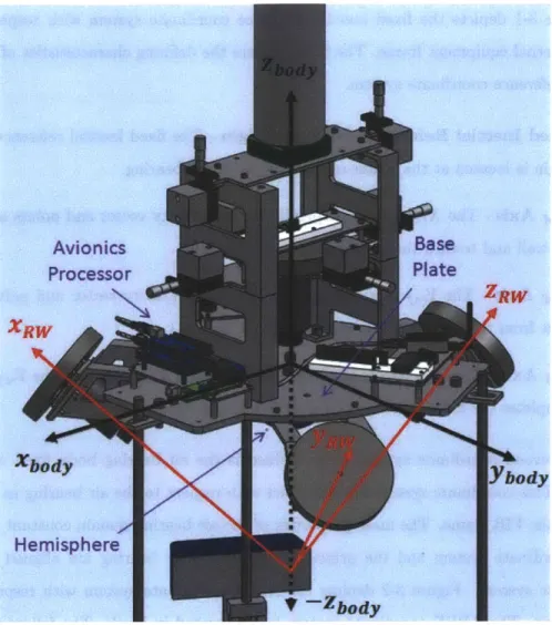
Air Bearing with Fixed Inertial Reference Coordinate System . Air Bearing with Air Bearing Body Fixed and Reaction Wheel System s . . . .
First Rotated Axis in Unrotated Frame
[61
. . . .
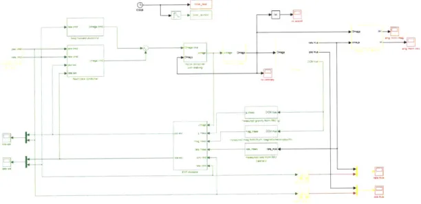
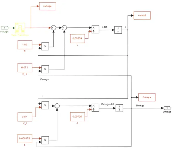
Reaction Wheel Frame in ABBF Frame . . . . Simulation Screen-shot . . . . Electrical Diagram of Direct Current (DC) Motor [16] . . . . . Reaction Wheel Plant Simulink Diagram . . . . Air Bearing Plant Simulink Diagram . . . . Direction Cosine Matrix Simulink Diagram . . . . Reaction Wheel Discrete State Space Diagram . . . . Air Bearing Discrete State Space Diagram . . . . Magnetic Field Measurement Diagram . . . . Gravity Vector Measurement Diagram . . . . Air Bearing Angular Rate Measurement Diagram . . . .Coordinate . . . . 52 . . . . 56 . . . . 58 . . . . 61 . . . . 63 . . . . 66 . . . . 67 . . . . 68 . . . . 74 . . . . 81 . . . . 82 . . . . 83 . . . . 84
3-15 Discrete Kalman Filter Process [34] . . . . 85
3-16 Angular Orientation Vector from Gravity Vector Measurement . . . . 90
3-17 State Update Diagram within EKF . . . . 93
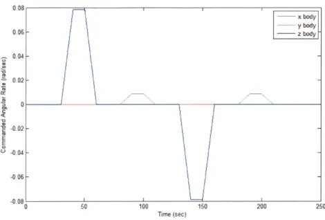
3-18 Commanded Angular Orientation and Rate Diagram . . . . 95
3-19 Commanded Angular Rate over Time . . . . 96
3-20 Commanded Angular Orientation over Time . . . . 97
3-21 Feedforward Control Diagram . . . . 99
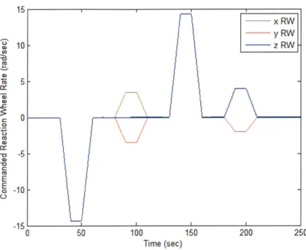
3-22 Commanded Reaction Wheel Rates - Zero IC . . . . 100
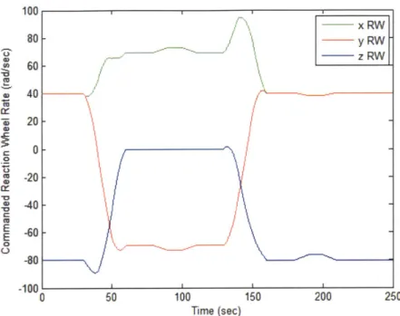
3-23 Commanded Reaction Wheel Rates - Nonzero IC . . . . 101
3-24 Feedback Control Diagram . . . . 104
4-1 Air Bearing Support Column with Rotating Hemisphere . . . . 109
4-2 Air Bearing SolidWorks Model . . . .. . . . . 111
4-3 Air Bearing Center of Mass Adjusters . . . . 113
4-4 Air Bearing Maximum FIR x Axis Rotation . . . . 115
4-5 Air Bearing Electrical Diagram . . . . 117
4-6 Avionics Component Plates . . . . 121
4-7 Air Bearing Communication Diagram . . . . 122
4-8 Air Bearing Reaction Wheel Model . . . . 129
4-9 Main and Auxiliary Arduino Control Cycle Diagram . . . . 138
4-10 Main Arduino Program Runtime . . . . 142
4-11 Main Arduino Program Start at Clock Pulse . . . . 143
4-12 Main Arduino and Auxiliary Arduino Runtime . . . . 144
4-13 External Magnetic Field Generator . . . . 145
5-1 IMU Mounting Location . . . . 154
5-2 Magnetometer and EMFG Field Vector . . . . 156
5-3 Magnetometer Measurements of Ambient Magnetic Field - EMFG Off . . . 157
5-4 Magnetometer Measurements over Ten ABBF Z Axis Rotations -EMFG On, N o G ains . . . . 158
5-5 Magnetometer Measurements over Ten ABBF Z Axis Rotations -EMFG On, Gains Applied . . . . 160
5-6 Maximum Step Input and Simulated/Actual Reaction Wheel Response - No
B rake . . . . 161
5-7 Maximum Step Input and Simulated/Actual Reaction Wheel Response -Braking Applied . . . . 162
5-8 Reaction Wheel Torque . . . . 163
5-9 40 Rad/Sec Step Input and Simulated/Actual Reaction Wheel Response -Braking Applied . . . . 164
5-10 Reaction Wheel State Space Model Bode Plots . . . . 165
5-11 Reaction Wheel Response to Sinusoidal Input . . . . 166
5-12 Reaction Wheel Angular Velocity Before and After CM Adjustment . . . . 169
5-13 Air Bearing Oscillation Due to Compressed Air Support Mechanism [44] . . 171
5-14 Uncontrolled Air Bearing Angular Rate . . . . 172
5-15 Friction Disturbance Torque acting on Air Bearing . . . . 173
5-16 Actual Angular Orientation and Error - Zero Initial Angular Momentum . . 174
5-17 Simulated Angular Orientation and Error - Zero Initial Angular Momentum 175 5-18 Actual and Simulated Reaction Wheel Angular Velocity - Zero Initial Angular M om entum . . . . 176
5-19 Actual Angular Orientation and Error - Nonzero Initial Angular Momentum 177 5-20 Simulated Angular Orientation and Error -Nonzero Initial Angular Momentum178 5-21 Actual and Simulated Reaction Wheel Angular Velocity - Nonzero Initial Angular Momentum . . . . 178
5-22 Actual Angular Orientation and Error -Nonzero Initial Angular Momentum, No Feedforward . . . . 179
5-23 Simulated Angular Orientation and Error -Nonzero Initial Angular Momen-tum, No Feedforward . . . . 180
5-24 MicroMAS with Coordinate System [36] . . . . 181
5-25 MicroMAS CONOPs Test on Air Bearing . . . . 182
5-26 Commanded Angular Orientation for MicroMAS Scenario . . . . 183
5-27 Air Bearing Angular Orientation and Reaction Wheel Angular Velocity -Zero Angular Momentum System . . . . 184
5-28 Air Bearing Angular Orientation and Reaction Wheel Angular Velocity - Net Zero Angular Momentum System . . . . 185
5-29 Reaction Wheel Angular Velocity - Zero and Net Zero Angular Momentum 185 5-30 Air Bearing Angular Orientation and Reaction Wheel Angular Velocity
List of Tables
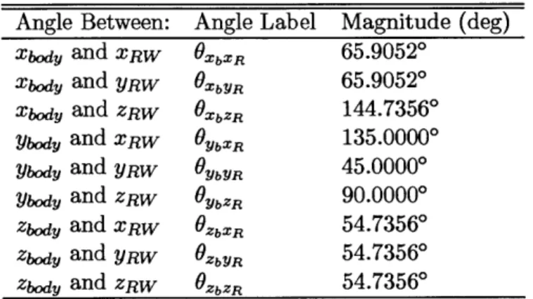
3.1 Angles Between RW Axes and ABBF Axes ...
3.2 Reaction Wheel Motor Constants ...
DoD STP ESPA Class Satellite Inertial Requirements
UNP ESPA Class Satellite Inertial Requirements . . .
Pololu Trex Motor Controller Power Requirements . . Five Volt DC-DC Converter Efficiency . . . . Avionics Stack Power Requirements . . . .
Arduino Mega Specifications . . . .
Flywheel Mass and Dimensions . . . . Arduino Memory Requirements . . . . External Magnetic Field Generator Specifications . . .
. . . . 110 . . . . 110 . . . . 116 . . . . 118 . . . . 118 . . . . 124 . . . . 129 . . .. . .. .. 140 . . . . 146
5.1 Average Rate and Variance of Gyroscope Measurements in Two Hour Fixed Test . . . . 152
5.2 Variance of Three Axis Magnetometer Measurements in Two Hour Fixed Test157 5.3 Magnetometer ABBF X, Y Axis Gains and Z Axis Bias . . . . 159
5.4 Reaction Wheel Magnitude and Phase Results . . . . 166
. . . 59 . . . 65 4.1 4.2 4.3 4.4 4.5 4.6 4.7 4.8 4.9
List of Acronyms
AAR Auxiliary ArduinoAB Air Bearing
ABBF Air Bearing Body Fixed
ADCS Attitude Determination and Control System
ADIS Analog Devices Inertial Sensor AFIT Air Force Institute of Technology AFRL Air Force Research Laboratory BRMS Bifocal Relay Mirror Spacecraft
CASTOR Cathode/Anode Satellite Thruster for Orbital Repositioning
CM Center of Mass
CMG Control Moment Gyroscope
CONOPs Concept of Operations CUSat Cornell University Satellite
DANDE Drag and Atmospheric Neutral Density Explorer DC Direct Current
DCFT Diverging Cusped Field Thruster DCM Direction Cosine Matrix
DIO Digital Input/Output DoD Department of Defense
DSACSS Distributed Spacecraft Attitude Control System Simulator EAPS Earth, Atmospheric, and Planetary Sciences
EELV Evolved Expendable Launch Vehicle
EMFG External Magnetic Field Generator
EMIC Electromagnetic Ion Cyclotron
ESPA EELV Secondary Payload Adapter
FASTSAT Fast, Affordable, Science and Technology Satellite
FIR Fixed Inertial Reference
FUSE Far Ultraviolet Spectroscopic Explorer GPS Global Positioning System
IC Initial Condition
I2C Inter-Integrated Circuit
IDE Integrated Development Environment
IMAGE Imager for Magnetopause to Aurora Global Exploration
IMU Inertial Measurement Unit ISS International Space Station
JPL Jet Propulsion Laboratory KLC Kodiak Launch Complex LED Light-Emitting Diode LEO Low Earth Orbit
LQE Linear Quadratic Estimator LQR Linear Quadratic Regulator LVLH Local Vertical, Local Horizontal MAR Main Arduino
MicroMAS Micro-sized Microwave Atmospheric Satellite MISO Master In Slave Out
MIT Massachusetts Institute of Technology MOSI Master Out Slave In
MPA Multi-Payload Adapter
NASA National Aeronautics and Space Administration NFOV Narrow Field-of-View
0/OREOS Organism/Organic Exposure to Orbital Stresses ODTML Ocean Data Telemetry MicroSatLink
P-Pod Poly-PicoSatellite Orbital Deployer
Polar BEAR Polar Beacon Experiment and Auroral Research PPR Pulse Per Revolution
PPT Pulsed-Plasma Thruster PSI Pounds per Square Inch RAX Radio Aurora Explorer
RPM Revolutions Per Minute RTC Real Time Clock
RW Reaction Wheel
RWCS Reaction Wheel Coordinate System
SCLK Serial Clock SDA Serial Data
SIV Standard Interface Vehicle
SNAP-1 Surrey Nanosatellite Applications Platform SPEX Space Phenomenology Experiment
SPHERES Synchronized Position Hold, Engage, Reorient, Experimental Satellites SPI Serial Peripheral Interface
SS Slave Select
SSL Space Systems Laboratory
SSTL Surrey Satellite Technology Ltd. STP Space Test Program
TACT Triaxial Attitude Control Testbed
TERRIERS Tomographic Experiment using Radiative Recombinative Ionospheric
Ex-treme ultraviolet and Radio Sources
TERSat Tethered Environmental Reconditioning Satellite
TIMED Thermosphere Ionosphere and Mesosphere Energetic and Dynamics
TOMS-EP Total Ozone Mapping Spectrometer - Earth Probe TRL Technology Readiness Level
TTL Transistor-Transistor Logic
UART Universal Asynchronous Receiver/Transmitter
UHF Ultra High Frequency
UNP University Nanosat Program
USAFA United States Air Force Academy USB Universal Serial Bus
Chapter 1
Introduction
1.1
Problem Statement
Developing and testing attitude determination and control systems (ADCS) in a university environment is a challenging task. Testing hardware in the loop ADCS systems in a lab-oratory is difficult due to the fact that ADCS subsystems often rely on the micro-gravity, reduced friction environment of space to perform as designed. Equipment needed to simu-late the key characteristics of the space environment for ADCS testing has been previously designed and built by organizations for internal use, but such equipment is not available for purchase. However, without hardware in the loop testing in a simulated micro-gravity, re-duced friction environment, ADCS engineers must rely solely on isolated component testing and simulation to validate the operation of the integrated ADCS subsystem. In this case, the subsystem will not be fully operational until it is on orbit where design and development errors likely cannot be corrected and can easily cause mission failure.
1.2
Motivation
Designing and developing an ADCS testbed for use within the Massachusetts Institute of Technology's Space Systems Laboratory (MIT's SSL) will provide student satellite design engineers the means to test ADCS hardware components, software algorithms, and inte-grated ADCS subsystems in a simulated micro-gravity, reduced friction environment. Many students at the undergraduate and even graduate level have no experience in satellite de-sign, much less ADCS subsystem design. Therefore, providing these students with a means
to validate hardware in the loop ADCS systems after conceptual designs and simulations have been produced is critical to satellite mission assurance. Student engineers as well as university faculty will be able to gain confidence in a given ADCS subsystem once "test as you fly" results are available to verify the ADCS system's simulation results.
1.3
Thesis Objectives
"
Design and develop a small satellite ADCS testbed capable of meeting the following requirements (further described in Section 2.5).o Provide class project support for estimation and control theory students. o Provide ADCS hardware component testing capability.
o Provide ADCS estimation and control algorithm testing capability. o Provide a platform for integrated ADCS subsystem testing.
" Verify the individual hardware components and baseline software used in the ADCS
testbed design.
" Validate the integrated ADCS Testbed and the supporting MATLAB based
simula-tion.
1.4
Thesis Outline
e
Chapter 2 covers the current state of satellite ADCS systems to include those of several small satellites being developed within the SSL. The chapter also discusses recent on-orbit ADCS failures. The chapter then covers the current state of ADCS testbed technology and concludes with the design requirements for the testbed developed as part of this thesis.e Chapter 3 discusses the development of the rotational air bearing simulation. First,
the chapter defines the coordinate systems used by the simulation and physical air bearing. The chapter then develops the air bearing's equations of motion. Finally, the chapter discusses the individual sections of the air bearing simulation, which include the reaction wheel and air bearing plant, the attitude estimation module, the attitude command module, and the attitude control module.
" Chapter 4 discusses the design and development of the physical air bearing to include the air bearing's structure, the power system, the avionics and communication sys-tem, the baseline set of attitude determination sensors, the baseline reaction wheel configuration, and the ground station computer. The chapter then covers the default software algorithms used by the air bearing's on-board processors. The chapter con-cludes by discussing the air bearing's external magnetic field generator (EMFG) and the benefits of integrating a SPHERES satellite on the air bearing.
" Chapter 5 covers the analysis of the air bearing and accompanying simulation. First,
the chapter covers attitude sensor characterization. The chapter then discusses re-action wheel response characterization. Air bearing disturbances like center of mass misalignment, compressed air vibration, and friction are discussed, and the chapter concludes by analyzing the results of several integrated system tests.
" Chapter 6 summarizes the thesis and discusses future work to expand the capabilities
Chapter 2
Background
2.1
Attitude Determination and Control System Overview
A satellite's ADCS system is used to stabilize and orient the vehicle as required by the
Concept of Operations (CONOPs) in the presence of external disturbance torques acting on the satellite. The ADCS system uses external references to determine the satellite's angular orientation with respect to a fixed inertial reference frame, usually an Earth centered, equatorial frame for Earth orbiting satellites. External attitude references include the Sun, Earth's horizon, the local magnetic field, and the stars. The satellite may also use inertial sensors like angular rate gyroscopes to measure angular rate and estimate the satellite's angular orientation between fixed inertial reference measurements, or while fixed inertial reference measurements are unavailable. For example, sun sensors cannot provide a fixed inertial reference measurement while the satellite is in eclipse [52].
For attitude control, ADCS systems impose torques on the satellite using a series of actuators. Thrusters of all shapes, sizes, and operating characteristics are used to produce external torques for attitude control, but they require an expendable fuel source. Magnetic torque coils and rods are also used to produce external torques on the satellite by acting against Earth's local magnetic field. Reaction wheels are common satellite attitude actua-tors because they produce internal torques that do not change the angular momentum of the satellite.
The ADCS system must maintain attitude control in the presence of constant distur-bance torques on the satellite. Disturdistur-bance torques are a function of the inertial properties of a satellite and its orbital location. For small satellites in Low Earth Orbit (LEO), the
most common disturbance torques are caused by solar radiation pressure, interaction with Earth's local magnetic field, aerodynamic drag due to Earth's atmosphere, and gravity-gradient torque. These disturbances exert external torques, which build up angular mo-mentum within the satellite. Reaction wheels may be used to maintain satellite stability and angular orientation in the presence of disturbance torques, but they can only store angular momentum and cannot dissipate momentum. When the reaction wheels are near their maximum angular momentum storage capability, external torques must be applied using thrusters or magnetic torquers to reduce the angular momentum stored in the wheels. This process is commonly referred to as desaturating the reaction wheels [52]
Satellite ADCS systems are designed to meet the requirements of their parent satellite making each ADCS system unique. Large satellites require attitude control actuators with large torque capabilities. Small satellites require actuators with less torque capability. Pre-cision payloads may require ADCS systems capable of determining and controlling attitude to within an arc-second (1/3600 of a degree), while some payloads may only require attitude control to within twenty degrees, or possibly no attitude control at all. ADCS systems must be custom designed and built for each satellite program with mission success often relying on the flawless operation of the ADCS system.
2.2
State of Small Satellite ADCS Systems
2.2.1
First Three Axis Stabilized Small Satellite
The first three axis stabilized small satellite was the Surrey Nanosatellite Applications Plat-form (SNAP-1) developed and built by Surrey Satellite Technology Ltd. (SSTL). SNAP-1 was launched on 28 June, 2000 on-board a Russian Cosmos rocket [51]. The primary mission of the 6.5 kilogram satellite was to demonstrate three axis attitude control as well as or-bital maneuvering [51]. The SNAP-1 satellite used a three axis magnetometer, an on-board camera, and a Kalman Filter for attitude estimation, and three magnetic torque rods in conjunction with a single pitch axis momentum wheel for attitude control [51]. SNAP-1 was also the first small satellite to use the Global Positioning System (GPS) for orbital position acquisition [51]. SNAP-1 was able to successfully control its attitude and use a butane fueled cold gas thruster to maneuver itself to within 2000 kilometers of its target satellite after starting more than 15000 kilometers away [51]. Though SNAP-1 did not rendezvous
with the target satellite, it proved that small satellites can achieve three axis stability and autonomously perform complex orbital maneuvers [51].
2.2.2 Space Test Program S26 Payloads
The current state of the art for small satellite ADCS systems is well represented by the payloads launched as part of the most recent Space Test Program (STP) mission. The mission, known as STP-S26 launched from Kodiak Launch Complex (KLC) in Kodiak, Alaska on 19 November, 2010 [?]. A converted intercontinental ballistic missile known as
a Minotaur IV was the launch vehicle used for the mission [?]. The Minotaur IV carried seven satellites to orbit; four EELV Secondary Payload Adapter (ESPA) class satellites and three cubesats [?]. The four ESPA class satellites attached to the launch vehicle using the Minotaur IV Multi-payload Adapter (MPA) in its first ever flight [?]. Two of the three cubesats were attached directly to the launch vehicle using Poly-PicoSatellite Orbital Deployers (P-Pods) [?]. The remaining cubesat, NASA's Nanosail D cubesat was integrated into the FASTSAT ESPA class satellite. The remaining five satellites making up the
STP-S26 mission include FalconSat-5, FASTRAC, STPSat-2, O/OREOS, and RAX [?]. Figure
2-1 shows the four ESPA class satellites integrated onto the MPA.
FalconSat-5 is the fifth satellite built by the Astronautical Engineering Department at the United States Air Force Academy (USAFA) and the second ESPA class satellite. The satellite is carrying four payloads, two of which are SERB ranked [37]. The primary mission of FalconSat-5 is to use its payloads to collect space weather measurements [37]. In order to operate its payloads as required, the satellite must achieve and maintain three axis stability. FalconSat-5 is equipped with four sun sensors, a three axis magnetometer, and an inertial measurement unit capable of measuring three axis angular rate. Using these sensors, FalconSat-5 estimates its attitude and uses three orthogonal reaction wheels for primary attitude control. Though three orthogonal reaction wheels allow for a fully controllable system, they provide zero redundancy. For reaction wheel desaturation, FalconSat-5 uses three orthogonal magnetic torque rods [37]. FalconSat-5's attitude estimation sensors and attitude control actuators represent a common ADCS configuration amongst current small satellites; a fully observable, fully controllable, zero redundancy system. FalconSat-5 is the far right satellite seen in Figure 2-1.
Figure 2-1: ESPA Class Satellites Mounted on Minotaur IV MPA For Launch [31]
FASTRAC is an ESPA class satellite designed and built by the University of Texas Nanosatellite Program at UT Austin [11]. The mission of FASTRAC is threefold. First, the satellite will demonstrate "on-orbit real-time GPS relative navigation solution[s] via real-time crosslink data exchange" [11]. Second, the satellite will demonstrate "on-orbit real-time attitude determination using a single frequency, C/A-code, reprogrammable GPS receiver" [11]. Finally, the satellite will demonstrate the use of a "micro-discharge plasma thruster" [11]. FASTRAC is made up of two sections that will separate in space [11]. Both require three axis attitude determination as a mission objective of FASTRAC, and they will each accomplish this using a single GPS receiver in combination with a three axis mag-netometer [11]. Once separated, the two sections will attempt to control relative distance, though attitude is not controlled on either section
[27].
One section carries a thruster that will be fired when the satellite's attitude is estimated to be within fifteen degrees of the de-sired thrust direction [11]. The other satellite carries an inertial measurement unit that will be used to estimate relative distance between the two sections [27]. FASTRAC's innovative means of attitude determination will provide additional attitude sensing capability tofuture satellites with little additional cost since many satellites already carry GPS receivers and magnetometers. FASTRAC is the front satellite seen in Figure 2-1.
NASA's Fast, Affordable, Science and Technology Satellite (FASTSAT) is an ESPA class satellite designed and built at the Marshall Space Flight Center in Huntsville, Alabama [2]. The mission of FASTSAT is "to demonstrate the capability to build, design and test a mi-crosatellite platform to enable governmental, academic and industry researchers to conduct low-cost scientific and technology experiments on an autonomous satellite in space" [2]. Though FASTSAT's mission objective is to be a cheap, quick, easy to develop spacecraft, the FASTSAT launched on STP-S26 carried several unique payloads, which include the first Nanosail to be deployed in low Earth orbit, a miniature stax tracker, a thermosphere temperature imager, and a miniature imager for neutral Ionospheric atoms and Magneto-spheric electrons [2]. Though the payloads will differ for each FASTSAT, the satellite bus will be primarily the same. The bus will be three axis stabilized with attitude estimation capability of 0.02 degrees and attitude control capability of two degrees [12]. FASTSAT is shown furthest back in Figure 2-1.
STPSat-2 is an ESPA class satellite built by Ball Aerospace [7]. STPSat-2 carries two payloads; SPEX (Space Phenomenology Experiment) will "evaluate sensor compatibility for the space environment" and ODTML (Ocean Data Telemetry MicroSatLink) will provide "two way data relay from terrestrial sensors to users" [14]. STPSat-2 is the first satellite to use STP's Standard Interface Vehicle (SIV), which uses a common satellite bus and payload integration system to allow for quick satellite design and build [7]. The satellite bus used by the SIV is ComTech AeroAstro's Astro-200 satellite bus, which provides all of the subsystems required to support the satellite's payloads [9]. The Astro-200 satellite bus carries the satellite's ADCS system, which uses three orthogonal reaction wheels to provide three axis stabilization [9]. The Astro-200 bus is designed to maintain Nadir pointing and can control its attitude to within 0.1 degrees. STPSat-2 is shown on the far left in Figure 2-1. NASA's second payload on STP-S26 is a three unit cubesat named Organism/Organic Exposure to Orbital Stresses (O/OREOS) Nanosatellite, which was designed and built at the Ames Research Center located at Moffett Field, California [3]. The mission of O/OREOS is to "characterize the growth, activity, health and ability of microorganisms to adapt to the stresses of the space environment" [3]. The cubesat has no active ADCS system, but uses several passive attitude control components to manage angular rates. Permanent magnets
known as hysteresis rods are mounted to the satellite's structure, which will eventually align the satellite with Earth's magnetic field [13]. Since Earth's magnetic field changes slowly with a sinusoidal component having a period equal to the satellite's orbital period, alignment with the magnetic field will be a relatively stable state.
The Radio Aurora Explorer (RAX) satellite is a three unit cubesat designed and built
by the University of Michigan and SRI International [18]. The mission of RAX is to "study
formations and distribution of magnetic field-aligned plasma irregularities located in the lower ionosphere" [181. To do this, RAX will carry a UHF radar receiver which will measure
"dense plasma structures forming between E and F layers of the ionosphere" [18]. RAX will estimate its attitude using a three axis magnetometer, a three axis inertial measurement unit, and a set of sun sensors [18]. RAX will not be actively controlled, but will use passive magnetic stabilization just like O/OREOS [18]. RAX will align itself with Earth's magnetic field for attitude stability.
2.2.3 University Nanosat Program
The University Nanosat Program is an Air Force Research Laboratory (AFRL) sponsored program that supports the development of small satellites in university environments across the nation. The University Nanosat Program (UNP) sponsors roughly ten to twelve schools in the development of ESPA class satellites over a two year period. The UNP program provides financial support to each university over the two year development period, and will sponsor the winning university satellite from each UNP cycle for launch [15]. The UNP program is currently in the initial phases of its seventh two year satellite development cycle. The winners of previous UNP cycles are a good representation for state of the art ESPA class satellites. The first to be discussed is the winner of the third UNP cycle. The winning satellite of UNP 3 is FASTRAC, which was launched in November, 2010 as part of STP-S26 as discussed above. The winning satellites from UNP 4, 5, and 6 will be briefly discussed below.
The winning satellite from UNP 4 is the Cornell University Satellite (CUSat), which is an
ESPA class satellite designed and built at Cornell University [43]. The mission of CUSat is
to demonstrate formation flying capability precise enough to diagnose the structural health and configuration of another satellite after orbital rendezvous [43]. CUSat is made of up two functionally identical spacecraft that will separate from each other after being ejected
from the launch vehicle [43]. Using differential GPS with three separate GPS antennas, each satellite section will be able to estimate its attitude to within two degrees as well as estimate its orbital position to within a few meters [43]. Each satellite half will then use pulsed-plasma thrusters (PPTs), torque coils, and miniature reaction wheels for three axis attitude control and orbital maneuvering [43]. An image of CUSat in a thermal chamber is shown in Figure 2-2(a).
(a) CUSat in Thermal Chamber (b) Computer Image of DANDE
Figure 2-2: UNP 4 and UNP 5 Winning Satellites [15]
The winner of UNP 5 is the Drag and Atmospheric Neutral Density Explorer (DANDE) satellite, which is an ESPA class satellite designed and built by the University of Colorado
[53]. DANDE's mission is to "explore the spatial and temporal variability of the neutral
thermosphere at altitudes of 350 - 100 kilometers, and investigate how wind and density
variability over 500 - 3000 kilometers scales translate to drag forces on satellites" [1]. For
attitude estimation, DANDE will use a three axis magnetometer in combination with two horizon crossing indicators (HCIs) [53]. DANDE will use two magnetic torque rods for
active attitude control with partial controllability
[53].
The satellite will also use viscous fluid nutation dampers for passive nutation damping [53]. Figure 2-2(b) gives a computer generated image of the DANDE satellite.---The winner of the most recent UNP competition, UNP 6 is the Oculus satellite, which is an ESPA class satellite designed and built by Michigan Technological University [24]. The mission of the Oculus spacecraft is to "demonstrate vision-based attitude control for tracking resident space objects" [24]. Due to the satellite's mission, it requires inertial and vision based attitude control [24]. For inertial attitude estimation, the Oculus satellite uses a three axis magnetometer and a three axis rate gyroscope [24]. For vision based attitude control, Oculus uses two cameras; the wide field-of-view (WFOV) camera for general target location and the narrow field-of-view (NFOV) camera for target tracking [24]. Oculus uses three orthogonal reaction wheels for attitude control, and three orthogonal magnetic torque rods for reaction wheel angular momentum desaturation [24].
2.2.4 MIT Space Systems Laboratory Satellites
MIT's Space Systems Laboratory develops space hardware for operation within the Space Shuttle, the International Space Station (ISS), and as free flying satellite systems. The SSL has had several payloads fly on the Space Shuttle and currently operates three SPHERES satellites on the ISS. The SSL's free flying satellite program includes a series of small satellites in various stages of the satellite design process. This section will cover three of the SSL's small satellites, which are CASTOR, ExoPlanetSat, and TERSat.
Cathode/Anode Satellite Thruster for Orbital Repositioning (CASTOR) is an ESPA class satellite designed by undergraduate and graduate students within the SSL. CASTOR was designed as part of the UNP 6 small satellite competition. CASTOR's mission is to "validate the performance and application of Diverging Cusped Field Thruster (DCFT) technology" [8]. A DCFT is a high efficiency, low thrust system that ionizes an inert gas (Xenon in this case), and propels the ionized gas using a set of permanent magnets. Though similar to a Hall Effect thruster, the DCFT uses permanent magnets rather than electromagnets to create the magnetic field required to accelerate the ionized gas. Hall Effect thrusters experience degradation due to the extremely hot ionized gas passing through the
engine nozzle. Due to differences in its structural design, the DCFT experiences significantly less degradation, which will allow the DCFT to operate at high efficiency for longer than a standard Hall Effect thruster [8].
The CASTOR satellite will provide the space support system necessary to operate the
Figure 2-3: SolidWorks Rendering of CASTOR Satellite
model of the CASTOR satellite is shown in Figure 2-3. In order to provide the power necessary to operate the DCFT as well as point the engine in the desired thrust direction, CASTOR requires three axis stability. For attitude estimation, CASTOR uses four sun sensors, two three axis magnetometers supported by a GPS unit, and a three axis inertial measurement unit
[8].
For attitude control, CASTOR uses three orthogonal reaction wheels, which provide full controllability but no redundancy in case of wheel failure. The reaction wheels are desaturated using three orthogonal torque coils [8]. An Extended Kalman Filter is used to provide CASTOR's attitude estimate using sensor inputs, and a linear quadratic regulator is used to provide attitude control commands to the reaction wheels. This ADCS system will allow CASTOR to point its solar panels towards the sun for battery charging, and point the engine in the desired thrust direction once per orbit as required by CASTOR'sCONOPs [8].
ExoPlanetSat is a three unit cubesat being designed and built by the SSL in coop-eration with MIT's Department of Earth, Atmospheric, and Planetary Sciences (EAPS). Figures 2-4(a) and 2-4(b) show ExoPlanetSat's internal component configuration and solar panel configuration respectively. The mission of ExoPlanetSat is to "be capable of detect-ing a transitdetect-ing Earth-sized planet in the habitable zone of the brightest sun-like stars"
[10]. Though there are large scale satellites on orbit whose mission is to detect exoplanets,
ExoPlanetSat will be capable of looking at stars that are too bright for large satellites with
---very sensitive optics to observe [10]. ExoPlanetSat is also meant to prove that small exo-planet searching satellites with low budgets can be designed and successfully operated. If successful, ExoPlanetSat will pave the way for many more copies of itself to be launched and pointed towards other bright stars in Earth's sky.
(a) ExoPlanetSat Component Configuration (b) ExoPlanetSat Solar Panel Configuration
Figure 2-4: SolidWorks Rendering of ExoPlanetSat
ExoPlanetSat will detect exoplanets by staring at a single bright star for a long period of time using the camera assembly shown in Figure 2-4(a). If an exoplanet orbiting the target star passes between ExoPlanetSat and the target star, ExoPlanetSat's optical system will be able to detect the decrease in light intensity from the target star [10]. In order for this type of exoplanet detection to work, the satellite's ADCS system must be capable of keeping the target star in almost exactly the same location with respect to ExoPlanetSat's optical system. In order to achieve such precision three axis attitude control, ExoPlanetSat uses two attitude control loops; a course and fine loop. The first attitude control loop, the course loop, estimates and controls the entire satellite's attitude to within sixty arc-seconds [10]. ExoPlanetSat will use a three axis magnetometer and a three axis gyroscope for course loop attitude estimation. For course loop attitude control, ExoPlanetSat will use three orthogonal reaction wheels and three orthogonal torque coils [10]. The second attitude control loop, the fine loop, estimates and controls the attitude of the satellite's optical sensor in the two axes perpendicular to the vector pointing towards the target star [101. The optical system estimates its attitude in the plane perpendicular to the target star vector using the pattern of stars surrounding the target star. This portion of the optical system works just like a star tracker. For fine loop attitude control, the optical system is mounted
---on a piezoelectric stage that can move in both axes perpendicular to the target star vector. The fine attitude control loop can estimate and control the attitude of the optical system to within one arc-second, which is the mission requirement for stabilizing the optical system with respect to the target star [10]. If successful, ExoPlanetSat will demonstrate the most accurate three axis stabilized attitude control system ever attempted on a cubesat.
Tethered Environmental Reconditioning Satellite (TERSat) is a second ESPA class satel-lite being developed within the SSL. TERSat is being developed as part of the seventh iteration of the UNP small satellite competition. TERSat's mission is to remove high en-ergy protons from the inner Van Allen Radiation Belt [41]. Energetic protons in the lower Van Allen Belt occur naturally but can also be caused by nuclear detonations in the up-per atmosphere. High energy protons damage satellites by causing single event upsets and transistor charging. Single event upsets occur when protons impact a satellite's memory storage devices and cause a bit to flip from a one to a zero or visa versa. A bit flip can cause an entire section of code to malfunction, which can ultimately lead to the failure of a satellite's avionics system. Transistor charging occurs when protons impact the silicon surrounding a transistor. Over time, the charge builds up to a point where the transistor can no longer flip from low to high rendering the transistor useless [25].
Energetic protons travel back and fourth along the Earth's magnetic field lines, bouncing off the Earth's atmosphere at the points where the magnetic field lines intersect with the Earth, once in the Northern and once in the Southern Hemisphere. TERSat will attempt to remove these energetic protons by emitting Electromagnetic Ion Cyclotron (EMIC) waves, which will coax the energetic protons to pass into Earth's atmosphere at one of the two
magnetic field line intersection points, rather than bouncing off the atmosphere and traveling back into space [41]. In order to emit EMIC waves, TERSat will need a four kilometer long antenna. To create this antenna, TERSat will release two tethers on opposite sides of the satellite. Each tether will extend out two kilometers creating the required antenna. Though the exact ADCS design has not been chosen, TERSat's primary structure will require three axis stabilization in order to align the tethers in the correct orientation for ejection. TERSat will likely use sun sensors in combination with a three axis magnetometer and three axis inertial measurement unit for primary body attitude estimation and three orthogonal reaction wheels and magnetic torque devices for attitude control [41].
Once extended several hundred meters from the primary structure, each tether will continue to deploy using gravity gradient force. However, during the initial phase of tether deployment, the gravity gradient force is not sufficient to deploy the tethers. Therefore, a short term ADCS system must be integrated into modules at the end of each tether. The sensor suite in each module must be able to determine the module's attitude and position with respect to the primary structure. The module will likely use cold gas thrusters to correctly position itself with respect to the primary structure, and deploy itself until the gravity gradient force is sufficient to continue tether deployment. TERSat will be the first
ESPA class satellite to attempt tether deployment on the kilometer scale. If successful,
TERSat will not only help remove satellite debilitating high energy protons from the Van Allen Belts, but it will also create a foundation for future complex ADCS systems in small satellites [41].
2.3
Satellite ADCS Failures
Satellite ADCS systems are often complex combinations of hardware components and soft-ware algorithms, and their flawless operation is a requirement for mission success. As can
be expected with such complex systems, there are many examples of satellite ADCS systems
failing either partially or completely once on orbit. Below are several examples of on-orbit
ADCS failures for satellites of all sizes. They are listed in chronological order.
The first American satellite, known as Explorer I, was designed and built by the Jet Propulsion Laboratory (JPL) in Pasadena, CA and launched in January, 1958 [30]. Ex-plorer I carried an instrument designed by James van Allen to measure the radiation en-vironment in space [30]. Explorer I and James van Allen are famous for discovering the high energy particle radiation belts now known as the Van Allen Belts [30]. Though a suc-cessful mission overall, Explorer I suffered from a debilitating attitude control failure. The satellite was permanently fixed to the rocket's fourth stage, which was spun during launch to provide stability and even out any thrust imbalances in the engine [301. The satellite also had four whip antennas mounted symmetrically about the spinning axis [30]. Once in orbit, the uncontrolled spinning satellite (and fourth stage) began to experience periodic communication loss [30]. This was eventually determined to be caused by the satellite's spin axis moving from the long, minimum inertia axis to the transverse, maximum inertia
axis [30]. Spinning satellites tend towards their minimum energy states, which is rotation about the axis of maximum inertia [30]. Spinning about the minimum inertia axis is an unstable equilibrium, and any source of energy loss will allow the satellite to change its rotation axis. Flexing in Explorer I's four whip antennas provided the energy loss necessary to transfer from the unstable minimum inertia axis to the stable maximum inertia axis, which led to periods of loss in communication due to incorrectly oriented antennas [301.
In November, 1986 The Polar Beacon Experiment and Auroral Research (Polar BEAR) spacecraft built by the Naval Research Laboratory was launched to measure auroral and ionospheric effects on radio frequency wave propagation [29]. The satellite was gravity gradient stabilized using a boom and end mass in combination with a pitch axis flywheel
[29].
Due to solar heating of the boom, the satellite began to sway back and forth away from the gravity gradient orientation. Eventually, the satellite flipped over and stabilized in the inverted orientation [291. The satellite operations team was eventually able to re-invert the satellite by allowing the momentum wheel to slowly spin down and then quickly spin up, producing enough angular rate to overcome the gravity gradient torque [29].
The Magellan spacecraft was deployed by the Space Shuttle in May, 1990 [30]. Magel-lan's mission was to travel to and map the surface of Venus. After achieving orbit around Venus and beginning the process of mapping Venus' surface using its synthetic-aperture radar, Magellan began to experience spontaneous increases in attitude error and angular rate about the spacecraft's body fixed x axis [30]. Engineers determined the problem to be in the solar panel pointing control loop [301. When the solar panels were near their commanded angular orientation, the step size of the solar panel actuator was greater than the angular error between the estimated and commanded solar panel orientation [30]. This caused the solar panels to flip back and forth on either side of their commanded orienta-tion [30]. The solar panel jitter excited a seven Hertz oscillaorienta-tion mode in the panels that led to the x axis attitude error [30]. Engineers were able to stabilize Magellan by adjusting the solar panel control algorithm [30].
The TOPEX-Poseidon satellite was designed in cooperation between the United States and France and launched in August, 1992 [30]. TOPEX-Poseidon's mission was to measure the topography of Earth's oceans in order to determine current flows and investigate the
El Nino weather phenomenon [30]. TOPEX-Poseidon used two star trackers with
to prevent damage to the star trackers, mechanical shutters would close if bright objects like the sun or moon moved to within twenty degrees of the star tracker's field of view [30]. After four months of operation, a single event upset caused the shutter control algorithm in one of the star trackers to always assume the star tracker was pointed towards a bright object and the shutter was closed [30]. Engineers reconfigured the control algorithm to use the remaining star tracker, which was successful until April, 1998 [30]. After six years of operation, degradation in the optical system caused an increase in background current. If the shutter were to close due to a bright object, it would continue to 'see' a bright object re-gardless of the shutter position, and it would not reopen [30]. Though engineers attempted to predict when the sun or moon would pass too close to the star tracker's field of view and maneuver the satellite to avoid such encounters, an unexpected reflection of the sun off of the star tracker's baffle caused the shutter to permanently close [30]. Engineers were able to save the satellite by rebooting, which cleared the single event upset in the first star tracker
[30]. Since it had only been used briefly, the recovered star tracker operated like new [30].
The Total Ozone Mapping Spectrometer satellite was developed by NASA's Goddard Space Flight Center as part of its Earth Probe series, hence the name TOMS-EP [30]. TOMS-EP was launched in July, 1996 on-board a Pegasus rocket [30]. The satellite was three axis stabilized with sun sensors, a magnetometer, and two Earth horizon sensors for attitude estimation, and thrusters, magnetorquers, and reaction wheels for attitude control [30]. Soon after launch, two of the sun sensors began providing erroneous measure-ments and were found to be cross-wired from installation [30]. The problem was solved by switching the two sensor outputs in the software algorithm [30]. After errors during magne-torquer operations arose, the polarities of the magnemagne-torquers were found to be inverted [30].
This problem was also mitigated by altering the software control algorithm [30].
The Lewis spacecraft was developed by NASA and launched from Vandenberg Air Force Base on 23 August, 1997 [30]. The Lewis spacecraft was designed to make high-resolution multi-spectral observations of the Earth from a 600 kilometer altitude [30]. After working out several avionics issues in the first few days on orbit, Lewis was placed in a zero rotation sun pointing safe mode [30]. Once in sun pointing mode, the operations crew retired for the evening. Lewis used two rate gyroscopes to measure angular rotation about the axes per-pendicular to the sun pointing axis and thrusters to control its attitude. While maintaining its sun pointing orientation, a thruster imbalance induced a spin about Lewis' sun pointing
axis, which was unobserved by the gyroscopes in the other two axes [30]. Furthermore, Lewis' solar panel face was the satellite's intermediate inertial axis, which may not be a problem for a satellite with little to no angular rate. However, the spin induced by the thruster imbalance was unstable about the intermediate axis [30]. By the time the satellite operators returned, Lewis had precessed to a spin about its major axis of inertia, which caused the solar panels to be edge on to the sun [301. The thrusters had depleted their fuel while trying to recover the satellite and the batteries were nearly dead and not receiving a charge [30]. Satellite operators permanently lost contact with Lewis on 26 August, 1997 just three days after launch [29].
The Tomographic Experiment using Radiative Recombinative Ionospheric Extreme ul-traviolet and Radio Sources (TERRIERS) microsatellite was designed and built by Boston University and launched in May, 1999 by a Pegasus launch vehicle [30]. After being placed in a sun synchronous 550 kilometer orbit, the satellite could not face its solar panels towards the sun, drained its batteries, and shut down [30]. Engineers determined the problem to be a sign flip which inverted the polarity of one of the magnetorquers used for attitude control, similar to the problem faced by NASA's TOMS-EP satellite [30]. Using a ground engineering model, the operations team determined that the satellite could successfully re-boot if the solar panel were to face the sun for a sufficient amount of time, and a software patch could be uploaded to correct the sign error [30]. After months of contact attempts, the operations team was never able to communicate with the TERRIERS satellite [30].
The Far Ultraviolet Spectroscopic Explorer (FUSE) spacecraft was designed and built
by NASA and launched in June, 1999 [29]. FUSE was used to make observations of distant
stars, galaxies, and other deep space objects [29]. The FUSE satellite used magnetic torque coils and reaction wheels for attitude control [29]. In 2001, two of the four reaction wheels failed, but engineers were able to reprogram the satellite's control algorithm to maintain attitude control using the two remaining reaction wheels and the magnetic torque coils [29]. After one of the six rate gyroscopes failed in 2001 and the other five showing degradation, engineers reprogrammed the satellite's attitude estimation algorithm to operate without gyroscopes completely [29]. Though several ADCS components were lost on the FUSE spacecraft, redundancy and clever engineering were able to extend the satellite's mission life.
![Figure 2-1: ESPA Class Satellites Mounted on Minotaur IV MPA For Launch [31]](https://thumb-eu.123doks.com/thumbv2/123doknet/14731502.573083/28.918.168.710.126.535/figure-espa-class-satellites-mounted-minotaur-mpa-launch.webp)
![Figure 2-8: TACT Dumbbell Style Air Bearing [19]](https://thumb-eu.123doks.com/thumbv2/123doknet/14731502.573083/46.918.164.754.124.403/figure-tact-dumbbell-style-air-bearing.webp)
![Figure 2-9: DSACSS Air Bearing Set [48]](https://thumb-eu.123doks.com/thumbv2/123doknet/14731502.573083/47.918.283.634.127.503/figure-dsacss-air-bearing-set.webp)