HAL Id: hal-02418014
https://hal.archives-ouvertes.fr/hal-02418014
Submitted on 18 Dec 2019
HAL is a multi-disciplinary open access archive for the deposit and dissemination of sci-entific research documents, whether they are pub-lished or not. The documents may come from teaching and research institutions in France or abroad, or from public or private research centers.
L’archive ouverte pluridisciplinaire HAL, est destinée au dépôt et à la diffusion de documents scientifiques de niveau recherche, publiés ou non, émanant des établissements d’enseignement et de recherche français ou étrangers, des laboratoires publics ou privés.
Fiber with Butterfly Wings: Creating Colored Carbon
Fibers with Increased Strength, Adhesion, and
Reversible Malleability
Daniel Eyckens, Chantelle Arnold, James Randall, Filip Stojcevski, Andreas
Hendlmeier, Melissa Stanfield, Jean Pinson, Thomas Gengenbach, Richard
Alexander, Lachlan Soulsby, et al.
To cite this version:
Daniel Eyckens, Chantelle Arnold, James Randall, Filip Stojcevski, Andreas Hendlmeier, et al.. Fiber with Butterfly Wings: Creating Colored Carbon Fibers with Increased Strength, Adhesion, and Re-versible Malleability. ACS Applied Materials & Interfaces, Washington, D.C. : American Chemical Society, 2019, 11 (44), pp.41617-41625. �10.1021/acsami.9b11826�. �hal-02418014�
Fiber with Butterfly Wings: Creating Colored Carbon Fibers with Increased Strength,
Adhesion, and Reversible Malleability
.Daniel J. Eyckens,1 Chantelle L. Arnold,1 James D. Randall,1 Filip Stojcevski,1 Andreas Hendlmeier,1 Melissa K. Stanfield,1 Jean Pinson,2 Thomas R. Gengenbach,3 Richard Alexander,1 Lachlan C. Soulsby,1 Paul S. Francis,1 and Luke C. Henderson.*,1
1
Deakin University, Waurn Ponds Campus, Geelong, Victoria 3216, Australia.
2
Université de Paris, ITODYS, CNRS, UMR 7086, 15 rue J-A de Baïf, F-75013 Paris, France.
3
CSIRO Manufacturing, Clayton, Victoria 3168, Australia.
Keywords: Carbon Fiber, Adhesion, Interface, Composite.
Abstract: Colored and color-changing materials are central to perception and interaction in nature and have been exploited in an array of modern technologies such as sensors, visual displays and smart materials. Attempts to introduce color into carbon fiber materials have been limited by deleterious impacts on fiber properties, and the extension of colored fibers towards ‘smart composites’ remains in its infancy. We present carbon fibers incorporating structural color, similar to that observed on the surface of soap bubbles and various insects and birds, by modifying the fiber surface through in situ polymerization grafting. When dry, the treated fibers exhibit a striking blue color, but when exposed to a volatile solvent, a cascade of colors across the visible region is observed as the film first swells and then shrinks as the solvent evaporates. The treated fibers not only possess a unique color and color-changing ability, but can also be reversibly formed into complex shapes and bear significant loads even without being encased in a supporting polymer. The tensile strength of treated fibers shows a statistically significant increase (+12%) and evaluation of the fiber-to-matrix adhesion of these polymers to an epoxy resin shows more than 300% improvement over control fibers. This approach creates a new platform for the multifaceted advance of smart composites.
Introduction
Since the development of carbon fiber composites in the 1960’s, it is commonly stated that you can have the fiber in “any color, as long as it’s black”i. Attempts to incorporate color have included blending with other fibers (e.g. dyed polyester or Kevlar®)1, but products based on this approach do not have the inherent high performance synonymous with carbon fiber. This blending is deleterious to properties such as fiber-to-matrix adhesion, recognized as a major hurdle to the widespread uptake of composite material2. Due to the chemical inertness presented by the surface of carbon fibers, the adherence of pigments and paints to artificially color this material is not a viable strategy.
Another source of color is that of structural color. This phenomenon is widely seen in nature, such as the vibrant bands of color on the surface of bubbles, peacock feathers, and the iridescent blue on the Morpho butterfly Morpho peleides (Figure 1d)6-9. Structural color has provided evolutionary advantages for organisms for communication, mating, defense, or camouflage10,11. In a similar vein, biology has often served as the inspiration for new materials12-19, with bone13 and nacre20-22 being prime examples of composites. The hard-soft interface of carbon fiber composites is analogous to the interlayer structure of nacre and the complementary interaction of dissimilar materials is responsible for its incredible strength and toughness9. Besides the obvious aesthetic appeal, the applications of a colored carbon fiber are yet unknown but have enormous potential23. This could range from simple colorimetric changes based on physical stimuli, through to high-end in situ performance management and monitoring during both manufacture24 and use25-29 via the imbedding of smart technologies (e.g. sensors) into the composites. Very recently, Xu et al.30 used atomic layer deposition of TiO2 to generate structural color on a carbon fiber fabric, but the time required to achieve these colors (hours to days), and the use of inert gases and low pressures remove viable scale up and industrialization strategies.
The possibility of installing structural color on carbon fiber immediately raises concerns on fiber performance (e.g. fiber strength and stiffness), interfacial adhesion within a polymeric support, and processability. However, previous coating of nanomaterials (graphene31, CNT32, etc.) on fibers has often shown beneficial effects on interfacial adhesion, which bodes well for the introduction of structural color. The fiber-matrix interface in carbon
fiber composites is recognized as one of the principal limitations in their application, which has spurred an enormous interest in fiber surface treatments. The ability to directly modify the interphase (i.e. the ‘handshake’ region between the discreet fiber and resin phases) thus presents a powerful means to enhance the performance, reliability, and adoption of composites on a broader stage. Moreover, the optimization of the fiber-to-matrix interphase is becoming increasingly important as industries seek to incorporate more thermoplastic matrix composites into structures, due to their rapid manufacturing time and recyclability33. The interface between carbon fibers and thermoplastics is typically very poor (and is not well researched due to the difficulty processing thermoplastic resins) as both the fibers and resin are chemically inert. Thus, the onus falls on the fiber surface to increase the adhesion in these components. Approaches such as plasma treatment34-37, chemical oxidation38-41, electrochemical42-48, and ‘wet’ chemical modification44-53, have previously been used to modify the surface of carbon fibers with limited success. The cost, time investment, and poor scale-up logistics make these processes difficult to retrofit to existing carbon fiber manufacturing equipment and have therefore had minimal impact on the industry. Results and Discussion
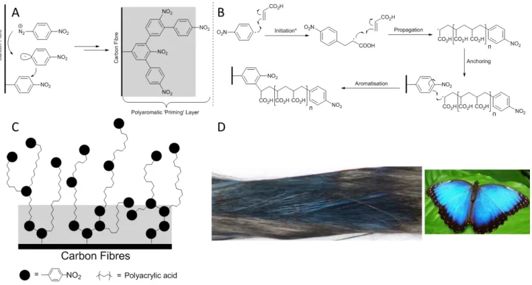
In this paper, an aqueous surface modification technique, based on an in situ polymerization procedure54,55, is used to rapidly graft an acrylic acid polymer film onto the surface of carbon fibers (Figure 1)ii. Originally reported as Surface Electroinitiated Emulsion Polymerization (SEEP)55, this process uses the facile reductive grafting of aryl diazonium salts onto electroactive surfaces in an elegant combination of both ‘graft from’ and ‘graft to’ approaches. The reduction of the aryl diazonium salts serves both as the initiator of the polymerization and a ‘priming layer’ that initially bonds to the surface and allows the in situ grown polymer to anchor to the surface (Figure 1a). Simultaneously, the reduced radical species can diffuse from the electrode surface and initiate polymerization via reaction with the acrylate monomers in solution (Figure 1b). This polymerization process then propagates and eventually anchors to the surface, via the previously installed nitrophenyl groups. After a polymer chain is deposited on the surface, the aryl initiator unit is exposed to the solution and thus can lead to branching effects (Figure 1c). This mechanism was proposed by Deniau et al.55 in the original report of this technique. A follow up study by Tessier et al.54 provided TOF-SIMS analysis demonstrating that as the polymeric film is ablated, the acrylic polymer detection decreases, while the presence of NO2 moieties increases just before the electrode surface is reached. This supports the concept of an initially grafted ‘priming layer’ of nitrophenyl groups which serve as an anchoring point for in situ grown polymer chains.
Figure 1. The proposed mechanism54 for in situ surface modification with acrylate polymers. (a) Initial grafting of the nitroaryl diazonium salt to the carbon surface occurs, generating a layer of reactive aromatic species, referred to as a ‘priming layer’ colored gray for clarity. (b) A small amount of reduced nitroaryl radical diffuses into the bulk solution, initiating the polymerization of acrylic acid. Propagation of this process gives short nitroaryl terminated polyacrylic acid radicals which diffuse to the fiber surface anchoring to the previously installed priming layer.
(c) The nitroaryl terminated polymers are now presented to the solution serving as a fresh layer of anchor points for freshly synthesized polymer. Note that in the original report of this work, hydrogen radicals generated by reduction of protons in the aqueous solution were also suggested as potential initiators (and thus termination units) of this process. These have been omitted here for clarity. (d) An image of the surface modified carbon fibers under white light highlighting the distinctive blue color consistent with thin film interference and the Morpho butterfly demonstrating a similar structural color.
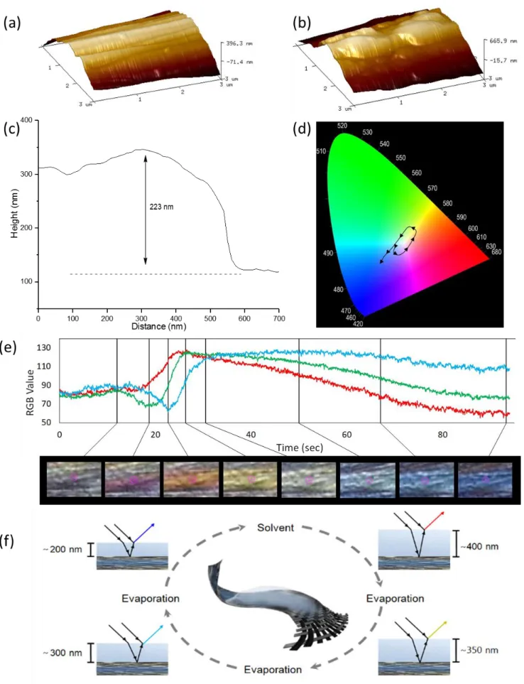
This process is less controlled (with respect to both polymer growth and branching effects) than other surface initiated polymerization techniques such as ATRP or RAFT. Nevertheless, the mild electrochemical potentials (±1 V), absence of metal catalyst, and inexpensive reagents make SEEP uniquely able to be retrofitted onto existing carbon fiber manufacturing infrastructure thereby increasing the immediate impact of this work. This treatment imbues the fiber with a deep blue color (Figure 1d). AFM images of the control (Figure 2a) and treated (Figure 2b) fibers showed polymer clusters on the treated fiber surface with a range of heights, commonly within 200-240 nm (Figure 2c)iii
iii
, consistent with the generation of a blue color via thin-film interference30. Other common structural color sources (e.g. diffraction gratings, multi-layer interference) are also possible but, in the authors’ opinion, are not likely. The AFM image (Figure 2a and 2b) shows no presence of such a diffraction grating, with the only features being the longitudinal striations along the fibre axis, typically observed for all carbon fibers. Also, considering the grafting solution consists of only one monomer (acrylic acid) and an aryldiazonium salt (4-nitrobenzenediazonium tetrafluoroborate) it is difficult to conceive the generation of multi-layers as this system, and the films generated therefrom, have been well characterized in prior studies55. The sporadic coloration is most likely due to localized areas of polymer growth and the variation in polymer film thicknesses is consistent with an uncontrolled ‘graft from’ process, such as that used in this work.
Moreover, the functionalization and polymer growth are likely related to the underlying crystallinity of the carbon fiber surface, which is known to be highly variable56. The nature of the carbon fiber surface is poorly understood but is known to be a heterogeneous mixture of graphitic and amorphous carbon structures. The latter possessing a moderate degree of sp3 hybridized carbon species56. The reduction of aryldiazonium salts can only occur at conductive portions of the fibre surface (i.e. graphitic) and thus the ‘priming layer’ of nitrophenyl moieties to which the polymer chains anchor to will co-locate with these regions. Therefore, it is expected that the colouration possessed by the fiber be inconsistent as this is a manifestation of the inherent nature of carbon fibers. This difference in density of coverage is observed by the comparison of high resolution C1s XPS spectra (Figure 2).
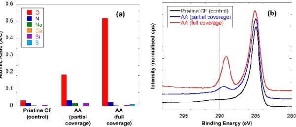
Figure 2 XPS figure showing atomic ratios X/C (a) and C 1s high resolution spectra (b) of pristine CF, CF partially covered with AA,
and CF fully covered with AA.
Analysis by XPS was used to confirm successful functionalization of the carbon fiber surface. Representative data (Figure 2) compares fibers either completely or partially covered with poly(acrylic acid) with pristine (uncoated) fibers. While the concentration of oxygen on the pristine fibers was very low (O/C = 0.03), the corresponding value for the fully functionalized fiber surface was measured to be 0.52, approaching that of pure poly(acrylic acid) (0.67), with O/C for a partially covered fiber to be in-between those extremes. The carbon 1s high-resolution spectra provide more specific evidence. The spectrum of pristine fibers displays a peak shape characteristic for graphitic carbon: a sharp narrow main peak with a high binding energy tail. The spectrum of fully covered fibers, in contrast, have a slightly broader main peak (hydrocarbon backbone) and a very prominent acid peak at approx. 289 eV. The
partially covered surface displays characteristics of both, the graphitic fiber structure as well as the acrylic acid coating.
Dropping acetone onto the surface of our functionalized fibers resulted in an initial dissipation in color followed by a series of different clearly observable colors as the solvent evaporated, through magenta, orange, yellow, green, and light blue, before returning to the characteristic blue color of the dry fiber (Figure 3d, 3e and Video S1). As can be seen in Video S1 (ESI), different colors are observed on the fibers at the same time points. This may arise from several factors including differences in the surface coverage of the polymer, rates of solvent evaporation, and angles of incidence, the latter of which as was also noted by Xu and co-workers30.
To the best of our knowledge, there has been no previous report of color-changing carbon fibers. In 2009, Peng et al.57 described electrochromatic carbon nanotube yarns, achieved by coating the yarns in polydiacetylene, which changed from blue to red in response to electric field, mechanical agitation, or thermal stimuli. The reported color change was reversible at low applied currents (~30 mA), but irreversible with higher currents and for thermal, mechanical, and solvent stimuli. Application of a solvent to the wings of the Morpho butterfly was reported to change their color58, which was attributed to changes in refractive index as the solvent filled the cavities within the wing nanostructures. Similarly, swelling of materials such as nanocrystalline cellulose and mesoporous organosilica films upon application of solvents has been shown to elicit changes in their observed color59,60. We therefore propose that the polymerization process generates a transparent thin-film on the surface of the carbon fibers that, while dry, results in the observed blue hue via thin-film interference. Upon addition of solvent, the polymer swells, changing the interference pattern giving the initial red/magenta color. Evaporation of the solvent thins the film and mediates the transition through to orange, yellow, green, light blue, and finally back to dark blue once the fibers are dry (Figure 3f). This sequence of color is consistent with a decreasing film thickness from approximately 400 nm to 200 nm30. This range is in good agreement with film thicknesses generated by others using this SEEP methodology, though measured on gold electrodes61.
When these fibers were placed into an epoxy-derived thermoset polymer, the color was immediately lost. Taken in the context of the above observations, this suggests that the film is soluble in the epoxy monomer, thus losing the thin-film interference effect. Using this rationale, the fibers should retain their blue color if a supporting polymer is used in which the polyacrylic acid polymer is not miscible. As polyacrylic acid is exceptionally polar, a lipophilic polymer (cyclic olefin copolymer (COC)), was injection molded over the colored fibers. In this instance, the blue color was retained, suggesting that the polyacrylic acid film is both thermally stable and retained at a similar thickness to that of dry treated carbon fibers (Figure 4a). Previous molecular dynamics simulations from our group have showed that interfacial adhesion is directly improved by penetration of fiber-surface-bound molecules into the polymer phase of a supporting resin47,63. The loss of color when the fiber was embedded in an epoxy resin indicates that the resulting composite should display enhanced interfacial adhesion compared to the untreated fiber.
Figure 3. (a) An AFM image of a clean carbon fiber showing typical striations. (b) Image of treated carbon fiber with a film on the surface
highlighting the coverage of these striations and coalescence of polymer clusters into a film on the fiber surface. (c) Typical height profile of the polymer attached to the surface of the fiber, showing a thickness consistent with the production of a blue color by thin-film interference. (d) A CIE plot of the color of the fiber during solvent evaporation extracted from footage (Video S1, Supporting Information) of the first 100 s after putting a few drops of acetone on the fiber, with arrows indicating the direction of transition. (e) RGB plot with video frames at selected time-points showing the wide range of fiber colors. (f) Schematic of the proposed process by which multiple colors are being generated. The dry fiber possesses a film thickness of between 220-240 nm, giving a blue color. Addition of a solvent causes the polymer to swell, subsequent evaporation, and thus progressive shrinkage of the polymer layer, results in refracted vs. reflected path length changes thereby smoothly transitioning through a range of colors until the original film thickness is once again present.
Surface defect
Drying
Reinforced Void
(i)
(ii)
(iii)
This electrochemical grafting treatment resulted in a statistically significant improvement in tensile strength (+12%). For almost all fibers, such as the carbon fibers used in this work, the existence of surface flaws has historically been observed as a critical determinant in fiber tensile strength [1,2]. This effect has led to carbon fibers being associated with a ‘weakest link in the chain’ model. However, the application of a sizing layer, again only adhered on the fiber surface, has previously been shown to increase single fiber tensile strength by up to 15% [3]. Although no mechanism for this improvement was provided in that work, here we hypothesize that the polymer grafting technique used in this work partially reinforced any defects or flaws at the fiber surface, thereby reducing premature failure at stress concentration points. As sizings are commonly applied to carbon fibers in an emulsion, it is conceivable that a heterogeneous micellar suspension would have limited opportunity to diffuse into any voids to reinforce them, and only provide coverage at the surface layer.
Whereas, in this work the homogenous solution of acrylic acid and aryldiazonium salts would infiltrate any voids or defects with relative ease. We ascribe the reinforcement effect observed here to the initiation of polymerization within the defect sites on the carbon fibers in addition to the surface (Figure 4c). The exposed interior of the fiber will also be conductive and provide a platform from which polymer chains can grow (Figure 4c (i)), resulting in reinforcement of any cracks and fissures by the in situ polymerized material (Figure 4c (ii)). The combination of this with the simultaneous polymer growth at the surface of the fiber coalesce to give the thin film responsible for the blue color (Figure 4c (iii)). This polymer reinforcement is unable to be removed by simple washing. A similar reinforcing effect was observed by Wagner et al.64 when the surface of electrospun multi-walled carbon nanotubes was modified with polymethyl methacrylate. In that case, improvements in tensile strength and Young’s modulus were 157% and 260%, respectively. While the improvements in our treated fibers are an order of magnitude smaller, the scale and widespread application of carbon fibers into modern structures equates to enormous potential impact in performance for composites worldwide.
Figur e 4.
(a)
Sample Tensile Modulus
(GPa)
Tensile Strength (GPa)
Interfacial Shear
Strength (GPa) IFSS Increase (%)
Pristine Fiber 239.5±0.80 2.96±0.08 14.19±0.69 - Treated Fiber 240.6±0.95 3.31±0.08* 58.34±4.16* 311%* Polymer Coalescence
(c)
(b)
(a)
Fiber color retained after injection molding COC polymer over a tow of treated fibers. Enlargement of the middle section clearly shows the presence of an electric blue color through the supporting matrix. (b) Improvement in tensile modulus, tensile strength, and interfacial shear strength, a minimum of 75 filaments were used to determine these values. *Denotes statistical significance (P < 0.05). (c) Proposed mechanism by which fibers increase tensile strength: (i) A depiction of the fiber surface possessing a defect from manufacture. (ii) The diffusion of monomers and nitroaryl diazonium species into these voids and initiation of the polymerization process within the surface defect. (iii) Coalescence of the polymer chains to give a reinforced void, thereby strengthening the overarching fiber at a molecular level. This effect, with the simultaneous external surface polymer, combine to give the thin film responsible for the observed blue color.
As noted previously the interfacial adhesion in any composite material is of critical importance to the ultimate properties, and thus utility, of a component. To complement the increased tensile strength and tensile modulus, we investigated the interfacial shear strength (IFSS) in an epoxy-derived supporting polymer. Using the single fiber fragmentation test, it was found that the IFSS relative to untreated fibers increased significantly, representing a 311% increase (Figure 4b). Thus, as a result of this treatment, not only have the physical properties of the surface modified fibers increased, but also the adhesion in a thermoset polymeric support, used in a wide range of applications, from automotive to aerospace. It is worth noting that the increase in IFSS would be partially due to the greater tensile strength of the fiber, and as such the critical fiber length will decrease as a function of this improvement. Nevertheless, the difference in magnitude of each the tensile strength (12%) and IFSS (311%) improvement suggests that there is a synergistic effect occurring at the fiber-resin interface due to this functionalization strategy. Previous work from our group has suggested that the entanglement and subsequent molecular ‘dragging’ of surface tethered molecules through the polymer phase under shear is responsible for large IFSS improvements, and is consistent with these observations44,62.
The tactile nature of these treated fibers differs substantially from the starting untreated fibers, in that the treatment causes the fiber bundles to become semi-rigid and to stick together. This is an extremely desirable effect of this functionalization as carbon fibers are traditionally unable to be processed into fabrics or woven materials without a ‘sizing’: a surface deposited film (often involving proprietary formulations) applied in the final stage of manufacture. Sizing is not only expensive, but also a major source of inconsistency in composite performance, with improvements65-68 and decreases69-71 in adhesion both attributed to sizing effects. The polymer grafted to the surface of the carbon fibers provides an alternative that allows for easy processing and minimizes potential problems due to stray fibers that can be inhaled or interfere with electrical components.
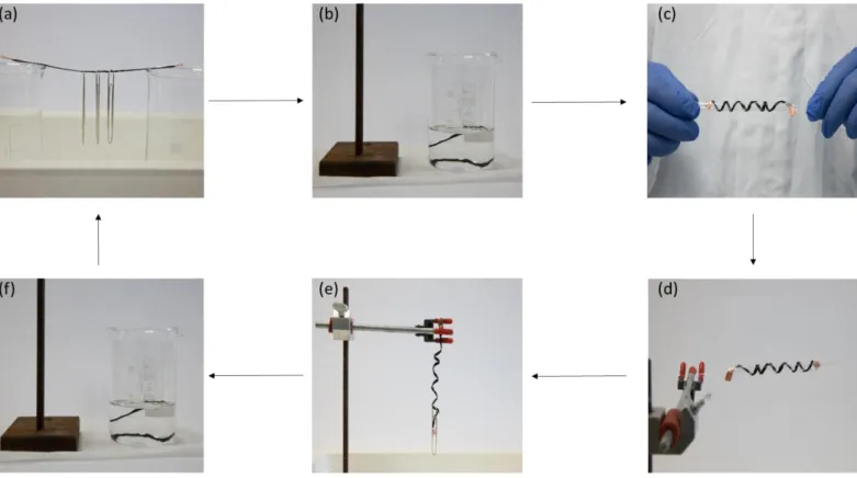
While investigating the durability of the polymer coating, we observed that the treated fibers became malleable immediately when washing with solvents and returned to their previous rigid state when the solvent evaporated. Moreover, the strength imbued into these fibers is substantial as they are able to support external weight (Figure 5a, Video S2). Placing a small amount of acetone onto the rigid fibers allowed them to bend and release the external weight (Video S3), which shows the potential of these uniquely surface functionalized fibers for stimuli responsive systems. We examined this temporary softening of the surface-bound polymer as a convenient means to manipulate the fibers into different shapes, as the ability to reversibly mold unsized carbon fibers would provide an enormous advantage over current technologies. Traditionally, fibers are knitted or woven into complex three-dimensional shapes or ‘preforms’, which is both time consuming and expensive. We first made the treated but unsized carbon fibers into a self-supporting rigid length (Figure 5a).
Figure 5. (a) A rigid length of treated carbon fibers supporting external load. (b) Submersion in acetone to soften the covalently bound polymer
coating (submersion time 10 seconds). (c) Molding the wet fibers to a given shape, in this instance a helical structure using a glass template; (d) Removal of the residual acetone impregnated within the carbon fiber tow. (e) The now dry fiber retains the shape of the template and is still strong enough to bear an external load without significant distortion of the helical motif. (f) Repeating submersion in acetone allows for completely reversible forming of these fibers without any property degradation.
Exposing the fibers to a solvent (Figure 4b, acetone in this instance) allowed the tow of fibers to be manipulated into shapes (Video S4) or complex patterns such as a helix using simple templates (Figure 5c). Allowing the solvent to evaporate or heating fibers to accelerate this process (Figure 5d) and removal of the template results in fibers which not only retain their shape but can still bear significant external loads (Figure 5e). This formability is completely reversible by reapplication of the solvent (Figure 5f) and does not result in any loss of fiber strength, versatility, or color. These reversible manipulations are impossible with traditional unsized, or indeed sized, carbon fibers as preforms are usually partially cured into a shape prior to complete part fabrication. Using fibers modified by this process in preforming would allow any small errors made during the partial cure to be removed by exposure to a solvent and reshaping.
Conclusion
In conclusion, we have demonstrated a rapid surface modification treatment that imbues carbon fibers with a blue color that undergoes a reversible color change through the visible spectrum upon exposure to a solvent and its subsequent evaporation. Due to the nature of the in situ grown polymer, and thus lack of molecular weight control, blue was the only color able to be imbued into the fibers. This treatment improves the tensile strength of the fibers, in addition to substantial gains to interfacial adhesion when in an epoxy supporting polymer. The former effect is attributed to the growth of polymers from within surface defects of the fiber, thus providing structural reinforcement and thus minimizing stress concentrations within the fiber structure. The latter effect is consistent with previous observations of molecular entanglement and interphase penetration of the surface bound molecules providing ‘molecular drag’ through the supporting matrix. This is supported by the miscibility of the grafted polymer in epoxy resin, resulting in immediate dissipation of the blue color, while retaining the blue color is possible in a lipophilic thermoplastic matrix, suggesting immiscibility of the grafted polymer into the interphase. The treated fibers able to be reversibly molded and heat set which provides unique opportunities to bypass expensive production hurdles, and greater flexibility in the design of carbon fiber composites. In the future, the ability to diversify the range of monomers applicable to this process, allowing a range of interfacial interactions and functionality, and the possible construction of multi-layer interfaces will be investigated.
Surface modification of carbon fiber
A 12k tow of pristine, unsized carbon fiber (Carbon Nexus) was submerged in an electrochemical cell as the working electrode, along with a platinum mesh counter electrode and an Ag/AgCl reference electrode. The carbon fiber tow was affixed with copper tape to improve contact with the electrode clips. The solution consisted of 4-nitrobenzenediazonium tetrafluoroborate salt (0.0237 g, 2 mM) and acrylic acid monomer (3.43 mL, 1 M) in 0.01 M H2SO4 (aq). A sweeping potential was applied to the system, from -1 V to +1 V at a rate of 0.01 V s-1 for 10 sweeps. Concluding this, the fiber tow was removed and thoroughly washed with dichloromethane, chloroform, ethanol and acetone (200 mL each), before allowing to dry under air. The fibers appear blue under white light and exhibit stiffness, maintaining the shape they were manipulated into while wet. This is consistent with the original reported procedure and all reagents were synthesized according to those reported55.
Initiating color change in treated fibers
A treated carbon fiber tow was subjected to low volumes (0.5-1 mL) of volatile solvent (acetone). This caused the blue color to disappear, then, as the solvent evaporated, the color of the fibers reappears and cascades through the visible light spectrum (red, orange, yellow/green, blue). With the complete evaporation of solvent, the fibers retain the initial blue color.
Molding and remolding
A treated carbon fiber tow maybe cast into a desired geometric shape (rod, circle, spiral, etc.) by softening in acetone, holding the fiber in the desired shape and allowing it to dry through evaporation. This drying may be accelerated through heating with no detriment to the fibers.
Supporting Information. Experimental procedures, AFM processes, CIE contour generation, and injection molding procedures are supplied.
Acknowledgement
The authors would like to thank Donna Squire for assistance in the acquisition of images and videos, Dr. Terri Field-Theodore for her assistance with developing schemes and figures. We thank the carbon fiber production crew at Carbon Nexus for providing the raw materials. This work was supported by Deakin University, the Australian Research Council Discovery Program (DP180100094), the ARC Centre for Future Fibers (IH140100018), the ARC Training Centre for Lightweight Automotive Structures (IC160100032), and the Office of Naval Research Global (N62909-18-1-2024). This work was performed in part at the Deakin node of the Australian National Fabrication Facility, a company established under the National Collaborative Research Infrastructure Strategy to provide nano and micro-fabrication facilities for Australia’s researchers. We thank Solvay Composites for their support of CA via a PhD stipend.
References
1 www.hypetex.com (Accessed 31/5/2019)
2 Zhandarov, S. & Mäder, E. Characterization of fiber/matrix interface strength: applicability of different tests, approaches and parameters. Compos. Sci. Technol. 65, 149-160, (2005).
3 Ben, S., Zhao, J., Zhang, Y., Qin, Y. & Rabczuk, T. The interface strength and debonding for composite structures: Review and recent developments. Compos. Struct. 129, 8-26, (2015).
4 Sharma, M. et al. Carbon fiber surfaces and composite interphases. Compos. Sci. Technol. 102, 35-50, (2014). 5 Jones, F. R. A Review of Interphase Formation and Design in Fiber-Reinforced Composites. J. Adhes. Sci. 24,
(2010).
6 Vukusic, P. & Sambles, J. R. Photonic structures in biology. Nature 424, 852, (2003).
7 Ahmed, R., Ji, X., Atta, Raghied M. H., Rifat, A. A. & Butt, H. Morpho butterfly-inspired optical diffraction, diffusion, and bio-chemical sensing. RSC Adv. 8, 27111-27118, 382E (2018).
8 Vukusic, P., Sambles, J. R., Lawrence, C. R. & Wootton, R. J. Quantified interference and diffraction in single Morpho butterfly scales. Proc. R. Soc. London, Ser. B 266, 1403-1411, (1999).
9 Eder, M., Amini, S. & Fratzl, P. Biological composites—complex structures for functional diversity. Science 362, 543, (2018).
10 Kristensen, A. et al. Plasmonic color generation. Nat. Rev. Mater. 2, 16088, (2016).
11 Caro, T. The Adaptive Significance of Coloration in Mammals. BioScience 55, 125-136, (2005).
12 Zhang, C., Mcadams, D. A. & Grunlan, J. C. Nano/Micro-Manufacturing of Bioinspired Materials: a Review of Methods to Mimic Natural Structures. Adv. Mater. 28, 6292-6321, (2016).
13 Wegst, U. G. K., Bai, H., Saiz, E., Tomsia, A. P. & Ritchie, R. O. Bioinspired structural materials. Nature Mater. 14, 23-36, (2014).
14 Siéfert, E., Reyssat, E., Bico, J. & Roman, B. Bio-inspired pneumatic shape-morphing elastomers. Nature Mater., (2018).
15 Wong, T.-S. et al. Bioinspired self-repairing slippery surfaces with pressure-stable omniphobicity. Nature 477, 443-447, (2011).
16 Heinzmann, C., Weder, C. & de Espinosa, L. M. Supramolecular polymer adhesives: advanced materials inspired by nature. Chem. Soc. Rev. 45, 342-358, (2016).
17 Zhao, Y., Xie, Z., Gu, H., Zhu, C. & Gu, Z. Bio-inspired variable structural color materials. Chem. Soc. Rev. 41, 3297-3317, (2012).
18 Parker, A. R. & Townley, H. E. Biomimetics of photonic nanostructures. Nat. Nanotechnol. 2, 347, (2007). 19 Barthelat, F., Yin, Z. & Buehler, M. J. Structure and mechanics of interfaces in biological materials. Nat. Rev.
Mater. 1, 16007, (2016).
20 Pan, G. et al. Learning from Natural Nacre: Constructing Layered Polymer Composites with High Thermal Conductivity. ACS Appl. Mater. Interfaces 9, 33001-33010, (2017).
21 Huang, C. & Cheng, Q. Learning from nacre: Constructing polymer nanocomposites. Compos. Sci. Technol. 150, 141-166, (2017).
22 Cheng, Q., Jiang, L. & Tang, Z. Bioinspired Layered Materials with Superior Mechanical Performance. Acc. Chem. Res. 47, 1256-1266, (2014).
23 McEvoy, M. A. & Correll, N. Materials that couple sensing, actuation, computation, and communication. Science 347, (2015).
24 Khoun, L., Oliveira, R. d., Michaud, V. & Hubert, P. Investigation of process-induced strains development by fiber Bragg grating sensors in resin transfer molded composites. Composites, Part A 42, 274-282, (2011). 25 Hu, N. et al. Investigation on sensitivity of a polymer/carbon nanotube composite strain sensor. Carbon 48,
680-687, (2010).
26 Abot, J. L. et al. Delamination detection with carbon nanotube thread in self-sensing composite materials. Compos. Sci. Technol. 70, 1113-1119, (2010).
27 Hu, N., Karube, Y., Yan, C., Masuda, Z. & Fukunaga, H. Tunneling effect in a polymer/carbon nanotube nanocomposite strain sensor. Acta Mater. 56, 2929-2936, (2008).
28 Dharap, P., Li, Z., Nagarajaiah, S. & Barrera, E. V. Nanotube film based on single-wall carbon nanotubes for strain sensing. Nanotechnology 15, 379-382, (2004).
29 Alamusi et al. Piezoresistive Strain Sensors Made from Carbon Nanotubes Based Polymer Nanocomposites. Sensors 11, 10691-10723, (2011).
30 Chen, F. et al. Facile and Effective Coloration of Dye-Inert Carbon Fiber Fabrics with Tunable Colors and Excellent Laundering Durability. ACS Nano 11, 10330-10336, (2017).
31 Zhang, X. et al. Interfacial Microstructure and Properties of Carbon Fiber Composites Modified with Graphene Oxide. ACS Appl. Mater. Interfaces 4, 1543-1552, (2012).
32 Kamae, T. & Drzal, L. T. Carbon fiber/epoxy composite property enhancement through incorporation of carbon nanotubes at the fiber–matrix interphase – Part I: The development of carbon nanotube coated carbon fibers and the evaluation of their adhesion. Composites, Part A 43, 1569-1577, (2012).
33 Holmes, M. Aerospace looks to composites for solutions. Reinf. Plast. 61, 237-241, (2017).
34 Scheffler, C. et al. Influence of microwave plasma treatment on the surface properties of carbon fibers and their adhesion in a polypropylene matrix. IOP Conf. Ser.: Mater. Sci. Eng. 139, 12046 (2016).
35 Dilsiz, N. Plasma surface modification of carbon fibers: a review. J. Adhes. Sci. Technol. 14, 975-987, (2000). 36 Yuan, L. Y., Chen, C. S., Shyu, S. S. & Lai, J. Y. Plasma surface treatment on carbon fibers. Part 1: Morphology
and surface analysis of plasma etched fibers. Compos. Sci. Technol. 45, 1-7, (1992).
37 Ho, K. K. C., Lee, A. F. & Bismarck, A. Fluorination of carbon fibers in atmospheric plasma. Carbon 45, 775-784, (2007).
38 Alexander, M. R. & Jones, F. R. Effect of electrolytic oxidation on the surface chemistry of type A carbon fibers - part 1 XPS. Carbon 32, 785-794, (1994).
39 Wu, Z., Pittman, C. U. & Gardner, S. D. Nitric acid oxidation of carbon fibers and the effects of subsequent treatment in refluxing aqueous NaOH. Carbon 33, 597-605, (1995).
40 Yumitori, S. & Nakanishi, Y. Effect of anodic oxidation of coal tar pitch-based carbon fiber on adhesion in epoxy matrix: Part 1. Comparison between H2SO4 and NaOH solutions. Composites, Part A. 27, 1051-1058, (1996).
41 Yumitori, S. & Nakanishi, Y. Effect of anodic oxidation of coal tar pitch-based carbon fiber on adhesion in epoxy matrix: Part 2. Comparative study of three alkaline solutions. Composites, Part A. 27, 1059-1066, (1996).
42 Leijonmarck, S. et al. Solid polymer electrolyte-coated carbon fibers for structural and novel micro batteries. Compos. Sci. Technol. 89, 149-157, (2013).
43 Liu, L. et al. Investigation of surface properties of pristine and γ-irradiated PAN-based carbon fibers: Effects of fiber instinct structure and radiation medium. Appl. Surf. Sci. 337, 241-248, (2015).
44 Randall, J. D. et al. Designing carbon fiber composite interfaces using a ‘graft-to’ approach: Surface grafting density versus interphase penetration. Carbon 146, 88-96, (2019).
45 Servinis, L. et al. Electrochemical surface modification of carbon fibers by grafting of amine, carboxylic and lipophilic amide groups. Carbon 118, 393-403, (2017).
46 Arnold, C. L. et al. Enhancing interfacial shear strength via surface grafting of carbon fibers using the Kolbe decarboxylation reaction. Composi. Sci. Technol. 159, 135-141, (2018).
47 Servinis, L. et al. Tailoring the fiber-to-matrix interface using click chemistry on carbon fiber surfaces. J. Mater. Chem. A 5, 11204-11213, (2017).
48 Eyckens, D. J. et al. Synergistic interfacial effects of ionic liquids as sizing agents and surface modified carbon fibers. J. Mater. Chem. A. 6, 4504-4514, (2018).
49 Servinis, L., Gengenbach, T. R., Huson, M. G., Henderson, L. C. & Fox, B. L. A Novel Approach to the Functionalisation of Pristine Carbon Fiber Using Azomethine 1,3-Dipolar Cycloaddition. Aust. J. Chem., 335-344, (2015).
50 Servinis, L. et al. Surface functionalization of unsized carbon fiber using nitrenes derived from organic azides. Carbon 54, 378-388, (2013).
51 Servinis, L. et al. A novel approach to functionalise pristine unsized carbon fiber using in situ generated diazonium species to enhance interfacial shear strength. J. Mater. Chem. A 3, 3360-3371, (2015).
52 Ehlert, G. J., Lin, Y. & Sodano, H. A. Carboxyl functionalization of carbon fibers through a grafting reaction that preserves fiber tensile strength. Carbon 49, 4246-4255, (2011).
53 Xu, Z. et al. Wettability of carbon fibers modified by acrylic acid and interface properties of carbon fiber/epoxy. Eur. Polym. J. 44, 494-503, (2008).
54 Tessier, L., Deniau, G., Charleux, B. & Palacin, S. Surface Electroinitiated Emulsion Polymerization (SEEP): A Mechanistic Approach. Chem. Mater. 21, 4261-4274, (2009).
55 Deniau, G., Azoulay, L., Bougerolles, L. & Palacin, S. Surface Electroinitiated Emulsion Polymerization: Grafted Organic Coatings from Aqueous Solutions. Chem. Mater. 18, 5421-5428, (2006).
56 Huson, M. G. et al. Heterogeneity of carbon fiber. Carbon 68, 240-249, (2014).
57 Peng, H. et al. Electrochromatic carbon nanotube/polydiacetylene nanocomposite fibers. Nat. Nanotechnol. 4, 738, (2009).
58 Potyrailo, R. A. et al. Morpho butterfly wing scales demonstrate highly selective vapour response. Nature Photonics 1, 123, (2007).
59 Zhang, Y. P., Chodavarapu, V. P., Kirk, A. G. & Andrews, M. P. Structured color humidity indicator from reversible pitch tuning in self-assembled nanocrystalline cellulose films. Sens. Actuators B, Chemical 176, 692-697, (2013).
60 Shopsowitz, K. E., Hamad, W. Y. & MacLachlan, M. J. Flexible and Iridescent Chiral Nematic Mesoporous Organosilica Films. J. Am. Chem. Soc. 134, 867-870, (2012).
61 Mévellec, V. et al. Grafting Polymers on Surfaces: A New Powerful and Versatile Diazonium Salt-Based One-Step Process in Aqueous Media. Chem. Mater. 19, 6323-6330, (2007).
62 Demir, B., Henderson, L. C. & Walsh, T. R. Design Rules for Enhanced Interfacial Shear Response in Functionalized Carbon Fiber Epoxy Composites. ACS Appl. Mater. Interfaces, 11846-11857, (2017).
63 Demir, B., Beggs, K. M., Fox, B. L., Servinis, Henderson, L. C., & Walsh, T. R. A predictive model of interfacial interactions between functionalised carbon fiber surfaces cross-linked with epoxy resin. Compos. Sci. Technol. 159, 127-134 (2018).
64 Liu, L. Q., Tasis, D., Prato, M. & Wagner, H. D. Tensile Mechanics of Electrospun Multiwalled Nanotube/Poly(methyl methacrylate) Nanofibers. Adv. Mater. 19, 1228-1233, (2007).
65 Fernández, B., Arbelaiz, A., Valea, A., Mujika, F. & Mondragon, I. A comparative study on the influence of epoxy sizings on the mechanical performance of woven carbon fiber-epoxy composites. Polym. Compos.25, 319-330, (2004).
66 Paipetis, A. & Galiotis, C. Effect of fiber sizing on the stress transfer efficiency in carbon/epoxy model composites. Composites, Part A 27, 755-767, (1996).
67 Downey, M. A. & Drzal, L. T. Toughening of carbon fiber-reinforced epoxy polymer composites utilizing fiber surface treatment and sizing. Composites, Part A 90, 687-698, (2016).
68 Yuan, X. et al. Optimization of interfacial properties of carbon fiber/epoxy composites via a modified polyacrylate emulsion sizing. Appl. Surf. Sci. 401, 414-423, (2017).
69 Zhang, R. L. et al. Effect of emulsifier content of sizing agent on the surface of carbon fibers and interface of its composites. Appl. Surf. Sci. 257, 3519-3523, (2011).
70 Dai, Z., Shi, F., Zhang, B., Li, M. & Zhang, Z. Effect of sizing on carbon fiber surface properties and fibers/epoxy interfacial adhesion. App. Surf. Sci. 257, 6980-6985, (2011).
71 Dilsiz, N. & Wightman, J. P. Surface analysis of unsized and sized carbon fibers. Carbon 37, 1105-1114, (1999).
(1) Hypertex www.hypetex.com (accessed 14 May 2019).
(2) Zhandarov, S.; Mäder, E. Characterization of fiber/matrix interface strength: applicability of different tests,
approaches and parameters. Compos. Sci. Technol. 2005, 65 (1), 149-160, DOI:
http://dx.doi.org/10.1016/j.compscitech.2004.07.003.
i Originally this was stated by Henry Ford with respect to the color of the Model T. Over the intervening decades this quote has been adapted to carbon fiber and numerous other examples.
ii The grafting of acrylate-derived polymers onto the surface of carbon fibers has been achieved by others previously and is typically achieved two ways. Leijonmarck et al. used anionic polymerization of acrylate monomers, requiring strictly anhydrous and oxygen free treatment conditions, was carried out under Argon in a glove box, for lithium ion sequestration in structural batteries.42 Xu et al. generated persistent radicals on the fiber surface via oxidation using - irradiation, or chemical species (H2SO4/KMnO4), followed by exposure of the activated material to gaseous monomers.53
iii
A reliable determination of film thickness is exceptionally challenging in this instance as the fiber is curved and possesses a characteristic corrugated structure, presenting as striations along the axis of the fiber.