HAL Id: inria-00440114
https://hal.inria.fr/inria-00440114
Submitted on 9 Dec 2009
HAL is a multi-disciplinary open access
archive for the deposit and dissemination of
sci-entific research documents, whether they are
pub-lished or not. The documents may come from
teaching and research institutions in France or
abroad, or from public or private research centers.
L’archive ouverte pluridisciplinaire HAL, est
destinée au dépôt et à la diffusion de documents
scientifiques de niveau recherche, publiés ou non,
émanant des établissements d’enseignement et de
recherche français ou étrangers, des laboratoires
publics ou privés.
simulating routing schemes on large-scale topologies
Luc Hogie, Frédéric Majorczyk, Dimitri Papadimitriou, Issam Tahiri
To cite this version:
Luc Hogie, Frédéric Majorczyk, Dimitri Papadimitriou, Issam Tahiri. simulating routing schemes on
large-scale topologies. [Technical Report] 2009, pp.10. �inria-00440114�
Simulating routing schemes on large-scale topologies
Luc Hogie
INRIA/CNRS/UNS/I3S Route des Lucioles 2004, 06902
Sophia Antipolis Cedex [email protected]
Dimitri Papadimitriou
Alcatel-Lucent Bell Copernicuslaan 50, 2018 Antwerpen [email protected]Issam Tahiri
Institut National des Postes et T´el´ecommunications (INPT)
Av. Allal El Fassi 2, Rabat [email protected]
Frédéric Majorczyk
Laboratoire Bordelais de Recherche en Informatique (LaBRI) 351, cours de la Lib´eration F-33405
Talence cedex [email protected]
ABSTRACT
The expansion of the Internet routing system results in a number of research challenges, in particular, the Border Gateway Protocol (BGP) starts to show its limits a.o. in terms of the number of routing table entries it can dy-namically process and control. Dynamic routing protocols showing better scaling properties are thus under investiga-tion. However, because deploying under-development rout-ing protocols on the Internet is not practicable at a large-scale (due to the size of the Internet topology), simulation is an unavoidable step to validate the properties of a newly proposed routing scheme. Unfortunately, the simulation of inter-domain routing protocols over large networks (order of tens of thousands of nodes) poses real challenges due to the limited memory and computational power that computers impose. This paper presents the Dynamic Routing Model simulator DRMsim which addresses the specific problem of large-scale simulations of (inter-domain) routing models on large networks. The motivation for developing a new sim-ulator lies in the limitation of existing simulation tools in terms of the number of nodes they can handle and in the models they propose.
Categories and Subject Descriptors
C.2.5 [Local and Wide-Area Networks]: Internet; C.2.1 [Net-work Architecture and Design]: Net[Net-work topology
Keywords
Internet; Routing; Topology; Simulation
1.
INTRODUCTION
Resulting from its expansion, the Internet routing system needs to accommodate an increasing number of Autonomous
Systems (AS) and an increasing number of IP routes. Ac-cording to [?] , in January 2007, the number of active BGP entries reached about 200k, and, in January 2008, about 250k. Mid-2009, this number hit 300k according to this re-port. Depending on the extrapolation model, by January 2011, the number of active routing entries of a core router would reach about 400 to 500k. Worst-case projections pre-dict that routing engines could have to process and maintain of the order of 1M active routes within the next 5 years. Note that the actual number of BGP routing table entries is higher and depends on the routing/forwarding table ratio (that varies between 2 and a low order of 10). The number of allocated AS numbers is steadily increasing and the number of advertised AS reached about 32k at the end of the third quarter of 2009. Thus, while the routing system actually prevents from any host specific routing information process-ing and maintenance (routprocess-ing state), storprocess-ing an increasprocess-ingly larger amount of network states over an increasing routing system is expensive and places undue cost burdens on net-work administrative units that do not necessarily get value from Routing Table (RT) size increases.
Additionally, the inter-domain routing protocol of the In-ternet, BGP (Border Gateway Protocol) [22], shows today several limitations in terms of stability and convergence is-sues. Indeed, routing updates require processing, and result in routing table re-computation and route re-selection that can lead to convergence delay and instabilities. BGP is a shortest AS path-vector algorithm that avoids AS-loops and eliminates the distance vector count-to-infinity problem but it is subject to Path Exploration. The latter phenomenon re-sults into in delaying BGP convergence time upon topology change/failure or policy change. In this context, a funda-mental dimension to take into account is the dynamics of the routing information exchanges between routers, in par-ticular, the routing topology updates that dynamically react to topological structure changes.
In brief, the Internet routing system is thus facing perfor-mance challenges in terms of scalability as well as dynamic properties (convergence and stability) that result into major cost concerns for network designers (topology vs. aggrega-tion) but also system designers (resulting from the architec-tural properties of BGP). Therefore, new routing schemes
have been proposed, in particular, compact routing [8] is promising.
Because it is not possible to deploy at a large-scale a routing protocol under study, simulation is an unavoidable step to validate the properties of a newly proposed routing scheme. Unfortunately, the simulation of inter-domain routing pro-tocols over large networks (order of tens of thousands of nodes) becomes a real issue. The limited memory and com-putational power of computers impose a number of compro-mises: the finer level of detail (granularity) we want to take into account in the simulation, the smaller network we are able to simulate. This paper presents the DRMsim simulator which addresses the specific problem of simulating routing protocols on large-scale networks. The paper is organized as follows. Section 2 describes the State of the Art in the domain of routing model simulation. Section 3 describes the models used in DRMsim: network model, topology genera-tors, routing/forwarding models, routing policy model, etc. Section 4 describes the protocols already implemented in DRMsim. Section 5 focuses on the architecture of DRMsim. Section 6 presents an interesting feature of DRMsim: the computational infrastructure included in the simulator. Be-fore concluding, Section 7 gives an example of an execution.
2.
OBJECTIVES AND CONTRIBUTION
Until recently, NS [3], a discrete-event simulator widely used in the networking community, did not comprise any BGP routing model. The recently introduced BGP++ module [1] solves this limitation and allows NS users to perform inter-domain routing protocol simulations. BGP++ chooses to port an existing BGP daemon from Zebra [10] to NS. This allows BGP++ to support most of Zebra daemon capabili-ties. Thus, it is now possible to use this daemon to build re-alistic inter-domain routing scenarios but not on large-scale networks due to the low level of simulation. SSFNet [4], another discrete event simulator, took a different approach than BGP++. An implementation of the protocol was de-veloped from scratch and validated. In SSFNet, a simulated router running BGP maintains its own forwarding table. It is thus possible to perform simulation with both TCP/IP traffic and routing protocols to evaluate the impact of a change in routing on the performance of TCP as seen from the end systems. J-Sim [2] is a simulation package imple-menting a component-based architectural approach to sys-tem description. It is a rich syssys-tem, with many modeling components related to modeling Internet protocols. Like NS, SSFNET and J-SIM choose to model the network at a high granularity, which does not allow large-scale simula-tions.
Other specialized simulators exist such as SimBGP [20] or C-BGP [21]. However, they are tailored for simulating BGP protocol specifics (and its extensions). Usually, these sim-ulators support an order of 1k nodes (thus relatively large scale topologies but not at the order of 10k nodes as re-quired for Internet routing model simulation). That is not the case of C-BGP that can simulate large-scale networks. These simulators are gradually updated to incorporate BGP feature set (e.g., Route Reflectors, internal BGP (iBGP) vs external BGP (eBGP), finer route selection rules for traffic engineering purposes, and BGP policies). These simulators are thus specialized and optimized (in terms of data
struc-tures and procedures) to execute BGP at the microscopic level and thus can not be extended to accommodate other routing protocol models.
All the simulators previously cited here above share many properties in common. As DRMsim, they all rely on discrete-event simulation (see Section 3.1). They are faster than real implementations. General simulators such as NS, SSFNet and J-Sim support other protocols such as TCP, which is ap-propriate for simulating protocol dynamics. However, they need so much resources to simulate the behavior of the pro-tocol that they are limited to networks of usually of few hun-dred nodes: large-scale simulations of ten thousands nodes are out of reach. BGP simulators such simBGP or C-BGP are specialized to BGP. They can simulate it accurately BGP and C-BGP is able to simulate large-scale networks. How-ever, they cannot be not easily extended to support other protocols, which is the goal of DRMsim. These two reasons motivate us to build a network simulator tailored to effec-tive routing: only the necessary components for simulating routing protocols over large-scale topologies are modeled.
3.
SIMULATION MODEL
3.1
Discrete-event simulation
DRMsim implements the discrete-event simulation (DES) approach. In DES, the operation of a system is represented as a chronological sequence of events (associated with any change in the state of the system). Thus, each event occurs at discrete points in simulation time and marks a change
of state in the system. Each event is assigned a
times-tamp indicating when it occurs. The simulation engine or-ders the events within its internal event list on the basis of events’timestamp. A DES thus typically implements three data structures: the state variables (which describe the state of the system), the event list (containing events that are to occur in the simulated future), and the global clock vari-able (that denotes the instant on the simulation time axis at which the simulation resides). An event is typically im-plemented by a data structure comprising the event’s times-tamp, the event type, and the event attributes. Other sim-ulation approaches include i) Time-slicing: the simsim-ulation clock advances with constant time steps. At every step, every entity in the simulation model is asked to perform. A major drawback of using time-slicing is that the simula-tion code directly depends on the time granularity: altering the time-step requires a complete revision of the code sim-ulated; and ii) Process-based : here each entity is seen as a autonomous execution item. In a process-based simula-tion, entities runtimes (threads, processes, etc.) must be synchronized. Most often the computational time spent to synchronize simulation significantly slows down the simula-tion engine. Also, the quality of process-based simulasimula-tion relies on the accuracy of underlying scheduling mechanisms, which often suffer from imprecisions or bugs.
3.2
Topology model
The Internet topology is complex to represent and repro-ducing a graph with similar properties for simulation pur-poses is hard to achieve. The reasons stem mainly because all necessary topological/structural information about this network is either unknown or not publicly available. Three levels of topology generation can be distinguished. Interface-level topology where every router interface is considered as
a node. Then, we find the router-level topology in which the routers are the nodes. Finally, the AS-level topology is the most interesting when simulating inter-domain routing, as autonomous systems are the nodes of the graph. The effi-ciency of routing protocols heavily depends on this network topology.
The topology model of DRMsim relies on the Dipergrafs [13] framework, which is dedicated to graph manipulation in the context of network simulation. More precisely, it provides a model for directed hypergraphs, which makes it a ver-satile tool for the representation of any network configura-tions, including asymmetric links, busses, ad-hoc networks, etc. Dipergrafs also provides a set of algorithms that are useful in the context of network simulation (graph metrics, exploration, topology generators, etc.) as well as a efficient implementation which allows the representation of very large graphs.
In order to simulate and compare existing and new rout-ing models as well as to predict their behavior at large scale, reproducing the important properties of the Internet topology is crucial. For this purpose, we have introduced through the Dipergrafs framework a set of topology gen-erators. Dipergrafs provides indeed a variety of parame-terizable topology generators, including Generalized Linear Preference (GLP) [6], and K-chordal networks [5], as well as bridges to INET [16], and BRITE [18].
3.2.1
Basic topology schemes
Dipergrafsincludes a set of native generators that enable
instantiation of basic topology schemes including
random-tree network, cliques, grids, chains, stars, etc. Analytic
studies generally quantify the performance of protocol when operating on such simple schemes. Being able to instantiate and simulate such schemes permits to validate or invalidate both studies and simulation.
3.2.2
Support for 3rd party topology models
Dipergrafscomes with a set of State of the Art topology
models. Most of these models were already implemented in tools available to the community. This is the case for INET [16] and BRITE [18]. They feature models based on preferential attachment and, respectively, power law dis-tribution and incremental growth. Third, one of the most complete source of information about the topology of the In-ternet can be found on CAIDA website (http://www.caida. org/). This information is available in the form of large data files. Dipergrafs proposes a topology generators which consists in a parser for CAIDA files. Although these gen-erators of Internet-like topology are commonly used, they do not accurately reproduce a variety of topological proper-ties of Internet such as the clustering coefficient which has a direct impact on routing performances. The clustering coef-ficient is defined as the percentage of triangular subgraphs among all connected node triplets in the entire graph.
3.2.3
Internet-like models
In order to go beyond available (and limited) topology gen-erators, Dipergrafs natively implements a topology gener-ator which uses GLP [6] attachment pattern. For the very same reason, a native generator for chordal graphs has been
implemented. Results using this topology generator are pre-sented in Section 7.
3.2.4
Composing topology models
The model for topology generation into DRMsim uses model composition, which allows to build complex topology schemes on the basis of several simpler ones. In practice, DRMsim takes as input as set of (potentially connected) vertices and a user-defined sequence of topology generators. DRMsim sequentially applies to this set of vertices the topology gen-erator, each of them generating/altering network links so as a number of constraints are met. The most common usage of topology composition is, first, the generation of a directed graph and, second, the alteration of all network links so that they all become non-directed. More complex generations are also possible.
3.3
Routing and Forwarding model
DRMsim is a packet-level simulator. As such, it features models and implementations for the two sole events which apply to packets: their transmission and reception. The sim-ulation of a routing process then consists in the dynamic gen-eration and computation of packet transmission and packet reception events. Unless a network failure is simulated, ev-ery packet emission event entails the creation of packet re-ception events. On packet rere-ception, the network nodes in-volved generate packet emission events, on the basis of their routing decision process.
This routing decision process, which is the generic model for routing protocols, is modeled as a mathematical function (L, R)route(r, l, m), where
m is the incoming message; r is the router the message m came from;
l is the link the router r used to forward the message m; L is a set of outgoing links where the message will be sent; R is a set of relay nodes to which the message will be sent. In practice all nodes that are destination nodes of links in L will receive the message but only those in R are allowed to relay it.
This model matches the general graph model which is used in DRMsim. It allows the development of simple vertex-to-vertex (with no consideration of the state of links) routing schemes, unicast and multicast routing, and, more gener-ally, more sophisticated routing schemes which exploit the peculiarities of symmetric, redundant links, etc.
From a programmatic point of view, this function is the only element required for the creation of a new routing scheme in DRMsim. In practice, a corresponding method is to be implemented when inheriting the class ”routing algorithm”, which declares it abstract.
The proposed routing model enables each network admin-istrative partition to apply its own routing policy without requiring explicit exchange of these policies neither mandate homogeneous policy rules for the routing scheme to properly operate.
3.4
Routing Policies Model
Based on the relationships between the different AS, each AS applies routing policies to decide which route updates it takes into account or excludes, and which route updates it forwards to his neighbors. Four different relationships be-tween AS exists ([14, 15, 7]): customer-provider, peering, mutual-transit, and mutual-backup. A customer AS remu-nerates his provider AS for connectivity to the Internet. So, a customer does not transit between two of his providers whereas a provider transits traffic for his customers. Two AS in a peering relationship exchange traffic between their customers. Two AS in a mutual-transit relationship provide connectivity to the Internet for each other.
We choose to model these relationships by labeling the edges with one of the different relationships. The programmer of a routing algorithm must take into account these relationships and respect the rules and preferences implied by these rela-tionships (e.g., a customer does not transit traffic between two of his providers).
3.5
Measurement model
3.5.1
Measures taking implementation
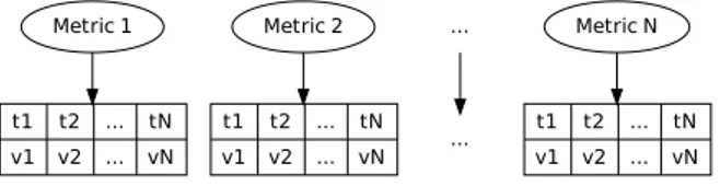
Metric 1 t1 v1 t2 v2 ... ... tN vN Metric 2 t1 v1 t2 v2 ... ... tN vN ... ... Metric N t1 v1 t2 v2 ... ... tN vN
Figure 1: Measurement Approach
Taking measures along a discrete-event simulation (Figure 1) can be performed in a number of ways. The most simple way consists in considering that all events will change the state of the system so as it is worthwhile to take new measures for all the defined metrics. Nevertheless, this approach fails to con-sider that a measure on the state of a system is not always obtainable in constant time complexity. Taking measure often requires additional –possibly time consuming– com-putations. Another approach consists thus in taking only the metrics that might have be affected after an event ex-ecutes. This approach reduces the computational overload presented hereinbefore but does not solve it: the event de-fines a set of metrics which are potentially affected by its execution but there may still exist metrics which were ac-tually not affected but for which new measures would still be computed. For this purpose, DRMsim uses a different approach which consists in taking a measure as soon as the corresponding metric has actually been affected. This ap-proach effectively reduces additional computations to the minimum. However, it introduces a dependency between the simulation and the measurement code: specifying a new measure imposes a modification of the simulation code.
3.5.2
Measures computed
As explained before, the main goal of DRMsim is to quan-titatively evaluate some of the main performance metrics of the routing models and especially those related to scalability
and stability. Thus, the metrics described below would be somehow the offspring of the simulations:
• Stretch: the stretch (of a routing scheme) is defined as the ratio over all source-destination pairs between the routing scheme path length and the minimum path length (actual distance) for the same source-destination pair. Intuitively, the stretch is a quality measure of the paths length increase as produced by a routing scheme compared to shortest path lengths. Shortest path rout-ing either AS-path length based (path vector routrout-ing) or cost metric based (link-state routing) are stretch 1. This metric is interesting to measure since compact routing schemes that produce reduced routing tables, are not always able to choose the minimum path for a given destination but on the other hand, the routing scheme should favor selection / computation of routes whose stretch remains closer to 1.
• Routing table size: It is calculated using the size of a single entry and the number of entries in the rout-ing tables (RT). RT size is directly related to routrout-ing system scalability because the less memory a router needs to store its entries, the more scalable the rout-ing system would be. Shortest-path routrout-ing schemes are incompressible: their lower bound on the number memory bits required to store the routing table en-tries they produce equal their upper bound -O(n log n) bits are required to store their RT entries [9]-. Note, when designing a routing scheme, there is a fundamen-tal trade-off between the stretch of a routing scheme and the size of the RT it produces.
• Communication cost: the dynamic nature of the rout-ing protocols such as those currently deployed over the Internet allows each router to be kept up to date with relation to non-local topological changes (result-ing from topological failures, addition/withdraw of routes and ASs). The latter information is exchanged be-tween routers by means of routing information updates (each router timely distributes to its own peers follow-ing specific selection criteria the routfollow-ing information received from other peers). Communication cost is de-fined as the number of routing update messages that need to be exchanged between routers to converge af-ter a topology change. Recently, [17] showed that the communication cost lower bound for scale-free graphs is at best linear up to logarithmic factors. The num-ber of routing updates may change according to the advertisement technique (time or event-driven). • Time Complexity : routing updates processing results
in recalculation of the RT entries and can lead to con-vergence delay, and instabilities but also processing overhead. The time complexity is defined as the num-ber of processing cycles needed by the routing scheme to recompute a RT entry for a given destination and insert it as part of the RT (or replace/remove an ex-isting entry in the RT).
By now, these metrics are the only metrics implemented in DRMsim but other ones can be implemented easily.
To validate and test DRMsim, we have implemented many different routing schemes, from simple ones such as source routing to more complex ones such as BGP. We describe these algorithms in the next Section.
4.
ROUTING PROTOCOLS IMPLEMENTED
4.1
Basic routing schemes
We first implemented a set of trivial routing models (source routing, random schemes, broadcasting, etc.). It allows us to check the correctness of the code and evaluate if our dif-ferent models described in the previous Section and the im-plementation of these models are able to scale on simple routing schemes. Then, we implemented the Routing Infor-mation Protocol (RIP) [11], a distance-vector routing algo-rithm, now obsoleted by more advanced techniques such as Open Shortest Path First (OSPF). Nevertheless, it is a good candidate to further validate our models and implementa-tion before implementing a scheme like BGP.
4.2
BGP
4.2.1
Full-fledge version
In The Full-fledge model, every node is considered as an AS. This means that it can simulate, in a way which is very close to reality, the external BGP communication (eBGP), but not the internal one (iBGP). In a router where BGP is running, many types of Routing Information Bases are stored. First, there is the Loc-RIB which contains all the paths known by the router and that are actually used in the forwarding process; in addition to this, a BGP router has an ADJ-RIB-IN and an ADJ-RIB-OUT for every adjacent node (which is linked to by a virtual TCP connection). The aim of these RIBs is to provide a neighbor-based filtering for both incoming and outgoing advertised routes. Only the loc-RIB was implemented. It is an aggregation of many routes taking into consideration the most important attributes (the path and its destination network) while leaving the flexibility for adding new ones according to simulation needs. The main characteristic of this version is the abitity to handle all events needed to establish, maintain, retrieve or to close a BGP session as defined in the finite state machine of a BGP peering session.
4.2.2
First optimization
In the first optimisation, we mainly relied on intuition and tried to simplify the Full-fledge model (previously described) by reducing the number of events and assuming that a BGP session has only two possible states. It is either IDLE or ESTABLISHED. This only has an impact on the establish-ment of the sessions. But after, there is exactly no difference between the two models. In term of performance, the ini-tial phase in every simulation will end faster if we consider similar scenarios.
4.2.3
Second optimization
Since intuition is never enough for getting an efficient model, we profiled the latter on different topologies. The lookup operation in the routing table (but also the forwarding ta-ble) was taking the largest part of the simulation execution time. This led us to write a third version of BGP which uses customized data structures: We had first to choose be-tween keeping or removing the forwarding table. It’s the
data structure containing just the necessary information for forwarding a packet. In a router it’s implemented on a spe-cial hardware whereas it’s not the case on our computers. Therefore keeping a forwarding table synchronized with the routing table is worthless. Having only a routing table (the Loc-RIB in our case) and rely on it to forward packets was a better solution. Secondly, and in order to improve the processing of update messages, routers stores known desti-nations in the form of bitsets. Then efficient logical oper-ations on both bit-sets of the peering routers are used to determine the entries of update messages are useful/useless. Finally, by designing the simulator so as to pre-fetch some potentially needed entries and prevent repetitive computa-tion, this second optimisation was a real improvement.
4.3
NSR
DRMsim also provides an implementation of the NSR [19] routing protocol. NSR is labeled routing scheme, where the node are labeled with names containing some information about the topology of the network, the location of the nodes in the network. NSR is a tree-based routing scheme which takes advantage of the specific property of networks that have low (logarithmic) diameter and a high clustering coef-ficient (such as the Internet). It computes short routes in the class of k-chordal graphs, i.e., graphs with no chordless cycles of length more than k. NSR can be quickly computed in a distributed way and achieves good additive stretch for such graphs. However, the simplicity comes at a cost of O(log n) bits per port needed to store the routing tables. In Section 7, we present an example of the simulator execution which tests the stretch performance of this routing model when running over three different topologies.
5.
SOFTWARE ARCHITECTURE
In this Section, we describe the software architecture of DRMsim and explain the choices that were made so as to be able to simulate large-scale networks and maintain mod-ularity of the code.
5.1
Module dependencies
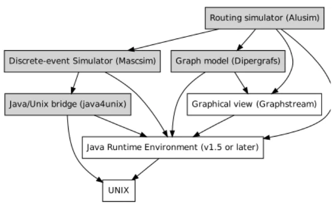
Java Runtime Environment (v1.5 or later)
UNIX Java/Unix bridge (java4unix) Discrete-event Simulator (Mascsim)
Routing simulator (Alusim)
Graph model (Dipergrafs)
Graphical view (Graphstream)
Figure 2: The dependencies of modules Figure 2 shows that DRMsim relies, through the java4unix framework, on UNIX facilities. DRMsim relies also on
for the discrete-event simulation engine. The Graphstream module can be used to obtain a view of the routing scheme.
5.2
Object-oriented model
DRMsim is an object-oriented application designed as a set of independent software components. In particular, it uses the Mascsim discrete-event simulation engine (itself derived from Madhoc[12], a mobile wireless network simulator), and
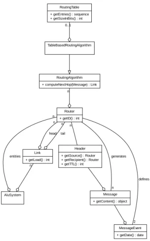
the Dipergrafs library. Corresponding simplified UML
class diagrams are represented on Figures 3 and 4. Figure 4 illustrates an important feature of the Mascsim simula-tion engine. A simulasimula-tion campaign is a set of execusimula-tion for individual simulation computations. Once all individ-ual simulation have been completed, the simulation cam-paign computes statistically confident results out of all re-sults collected. The way individual simulation are executed is called an ”execution strategy”. We have developed 3 dif-ferent strategies. First the ”sequential execution” takes the set of individual simulation jobs in a sequence and process them all in a row. Second, the ”multi-thread strategy” in-stantiates a predefined number of threads and uses them to execute the jobs in parallel. This technique allows to take advantage of multi-core workstations. Last, the ”distributed strategy”, which is still under tests, use the RMI technology to distribute the individual simulation jobs across a set of cooperating workstations.
The main objective of DRMsim is to enable the simula-tion of large networks. With this objective in mind, the main difficulty is the instantiation of large graphs. Graph libraries available to the community all exhibit poor per-formance when it comes to build graphs composed of thou-sands of nodes. We noticed three shortcomings. First, the data structures they use have significantly slow access time
which makes complex operations impracticable. Second,
their memory utilization when instantiating dense networks (networks having high average degree) overloads commod-ity PC hardware. Third, the graph model(s) supported are sometimes too restrictive, that is it turns out to be impossi-ble to models topologies like busses (Ethernet) or symmet-ric links. This motivated the development of Dipergrafs.
Dipergrafsdata model is designed with performance
ob-jectives in mind. In particular it makes uses of four coupled incidence lists (incidence lists are known to provide O(1) operations). Each graph element (either vertex or edge) is identified by an integer. This ID is used for indexing in the lists. Memory utilization is better when the address space is dense. The main drawback is that the simulator user needs to specify the number of vertex/edge the topology gener-ator will instantiate. This mechanism is also used in the routing table model, where indexing relies on vertex’ ID. Everywhere in DRMsim, we avoided the use of hash tables. Their convenience made them highly popular, but they se-cretly have an important role in the reputation Java has for poor computational efficiency.
5.3
Graphical monitoring of the routing
pro-cess
DRMsim comes with a set of command-line tools which al-low the execution of simulation campaigns and the extrac-tion of results. Also, for the purpose of monitoring, which is of paramount importance when prototyping distributed
ap-Router + getID() : int AluSystem entities n Link + getLoad() : int head n tail n Header + getSource() : Router + getRecipient() : Router + getTTL() : int n n Message + getContent() : object generates n MessageEvent + getDate() : date RoutingAlgorithm + computeNextHop(Message) : Link n TableBasedRoutingAlgorithm RoutingTable + getEntries() : sequence + getSizeInBits() : int 0..1 defines 2
Figure 3: The UML model for the
MeasureList Result + getID() : string n Metric + takeNewValue(System) : object + acceptValue(object) : boolean + getName() : string Unit + getName() : string + isCompatibleWith(Unit) : boolean n Measure + getDate() : date + getValue() : object stores n Simulation + getEventList() : sequence + process() : Result Configuration + getValues(string) : string + getID() : string System Event + getDate() : date + compute() : void schedules n ExecutionStrategy + process() : void MultiThreadExecution + getNumberOfCores() : int RMIDistributedExecution + scanLAN() : set process n
Figure 4: A summarized view of the core architec-ture of the Mascsim simulator.
Figure 5: Screenshot of the rendering pane
plications, an aircraft view of the network is also provided, as illustrated on Figure 5.
6.
COMPUTATIONAL INFRASTRUCTURE
An important objective of DRMsim is to enable simulation of large networks. In order to achieve this goal, it benefits from the Mascsim simulation engine to run distributed sim-ulations. The main idea is that simulation results are valid only if they were statistically computed out of the results of numerous simulations. The set of independent simulation processes can be seen as a pool of independent jobs to be executed. There are different possibilities to execute this set of jobs: on one computer, sequentially or in parallel by using multi-core CPUs or on several computers by using Remote Method Interface (RMI) or Web services.
6.1
Multi-core
Most today’s commodity workstations embed a multi-core computational unit (CPU). As of 2009, dual and quad core computers are commonly available on the market. It is in-teresting to use this capability to launch several threads, each computing one simulation.
6.2
RMI
The distribution strategy of Mascsim is to distribute this set of jobs among a set of calculators. In practice, jobs can be distributed amongst computers belonging to the same Local Area Network (LAN). They typically run Linux pre-configured distributions, which pose no firewall issues. Hence, discovering services on a LAN is easy: the Mascsim
simu-lation client scans the LAN to search for a Mascsim server, and it uses a random (uniform law) load-balancing scheme for distributing simulation jobs. Network communication is carried out using Sun’s Remote Method Interface (RMI). Just like any RMI remote objects, Mascsim remotes are passive: they wait from incoming request. The RMI-based
Mascsimarchitecture is decentralized in the sense that it
does not involve a central source of information or coordina-tor. Available peers dynamically discover themselves —by scanning the network— as they need computational effort. From a security point of view, Mascsim considers a trusted network environment.
6.3
Grid
Another possibility to compute the simulations is the use of a Grid. Communications in the grid are centralized and HTTP-based. It relies on a set of Web services (implemented in PHP).
An Mascsim grid peer is an active component. Instead of waiting for incoming connections (like traditional server ap-plications do), it actively notifies the central server that it is running and is waiting for simulation jobs. The central server is then always aware of the peers constituting the grid. It can then assign jobs to peers. The role of a peer is then to retrieve assigned jobs from the central server, to execute them and to send the result back to the server.
6.3.1
Deployment
Deployment consists in the initial installation of the dis-tributed software and in its steady update. It is a serious issue of distributed applications whose the emphasis linearly grows with the number of nodes involved. Mascsim solves the deployment issue by opting for a solution inspired from network booting. Mascsim peers do not have a copy of
Mascsim’s binaries. Instead they only store a tiny bootstrap
application (written in bash) that contains the minimum ex-ecutables to download the last version of the binaries and run them.
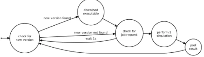
check for new version
download executable new version found
check for job request new version not found
wait 1s
perform 1 simulation
post result
Figure 6: Deployment state diagram
In practice, the bootstrap application connects to the
Masc-simcentral server from which it identifies, downloads, and
executes the last version of the code. Upon termination, the code is deleted from the hard disk (of peer(s)) and will have to be downloaded again on next startup. This mechanism ensures that only the last version of the simulation engine runs on the grid as well as it greatly simplifies deployment on the grid. This automatized deployment only requires that the bootstrap application is copied to network nodes.
6.3.2
Result caching
The Mascsim simulation engine takes a textual configura-tion as input and produces binary data as a result. It is a deterministic function, meaning that two same input config-urations will produce the exact same output. The hash code of a a textual input configuration is used as its identifier. It permits result caching. More precisely, once the Mascsim simulation engine has computed a result out of a given input configuration, it publishes it to the cache. If, in the future, the simulator is invoked with the same configuration, the computation of the result will be skipped, since it is already available in the cache. This behavior is very useful in the context of practical experimentation since we have observed that the same simulation is done many times.
The Mascsim architecture define two caches: the global cache and the local cache.
The global cache is located on the central server. It is acces-sible through a set of web-service implemented in PHP. This cache must take two things into account: it is shared by all users and it is accessed by encapsulated network protocol. Its design must optimize disk space and network utilization. Both objectives are optimized by the use of data compres-sion: all the result data files stored in the global cache are compressed according to the Lempel-Ziv algorithm (as im-plemented in gzip).
In the context of confidential experimentations, it is not ac-ceptable that results are deposited in a publicly available data set. In this case, the user can disable the use of the global cache. Instead, Mascsim will manage a cache located on the local hard drive.
6.3.3
Automatic error reporting
Mascsimmakes no compromise on its execution flow. For
the sake of code simplification and simulation accuracy, ex-ecution errors head to a brutal termination of the simulator and to the generation of a detailed error report. On the one hand, local execution errors are notified to the user by the termination of the simulator and the printing of the error report to the standard output (typically the console). On the other hand, remote execution errors do not terminate the simulation process: the faulting peer publishes the error report to the central server and terminates the simulation job that was assigned to him. The simulation job will be assigned to another peer.
7.
USAGE EXAMPLE
In this Section, we present a sample execution of DRMsim so as to evaluate its scalability. We evaluated DRMsim with the NSR [19] routing scheme. The choice of NSR is moti-vated by two facts: NSR is a complex routing scheme and NSR is a new routing scheme. Testing and evaluating new routing schemes is indeed the goal of DRMsim. All the sim-ulations were computed on a computer with an Intel Core 2 Duo T7500 2.2 GHz with 4 GB of RAM (the JVM was limited to 2 GB) running Ubuntu in 64 bits with a kernel 2.6.28 and with a JRE 1.6.0. The simulations never lasted more than 15 minutes on NSR even with 3500 nodes. On this same computer, we were able to simulate BGP with 10000 nodes in less than an hour.
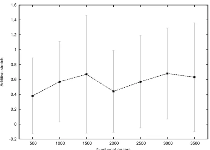
-0.2 0 0.2 0.4 0.6 0.8 1 1.2 1.4 1.6 500 1000 1500 2000 2500 3000 3500 Additive stretch Number of routers
Figure 7: The evolution on the number of nodes of the additive stretch (average and standard devia-tion) generated by the NSR routing protocol applied to power-law networks obtained using linear prefer-ential attachment.
DRMsim is able to export results in the gnuplot format. On the Figure 7, we present the results for the additive stretch functions of the number of nodes (up to 3500), obtained for NSR on a GLP Topology. The additive stretch is defined as the difference in number of hops between the routing scheme path length and the minimum path length (actual distance) for the same source-destination pair. For a given simulation, it was calculated by computing the average and the standard deviation of this metric over a hundred of random routings. For a given configuration (number of nodes), we ran 30 sim-ulations with a different seed for the pseudo-random gener-ator and compute the average over all the 30 simulations. These simulations show that the additive stretch of NSR turns out to be very small on power-law networks (with lin-ear preferential attachment) which are considered to be good representations of Internet AS network topologies.
In the same way, we ran simulations of NSR on chordal graphs and grids. These simulations confirmed the theoret-ical results: NSR has a small additive stretch (inferior to 1) in chordal graphs and has poor performance on graphs which include many big holes (chordless cycles) such as grids. Although some work still needs to be done to optimize parts of the simulator, these first results show that DRMsim is able to simulate complex protocols on large topologies in reasonable time.
8.
CONCLUSION
The expansion of the Internet results in a number of chal-lenges at the routing system level: the Border Gateway Protocol (BGP) starts to show its limits in terms of the number of routing tables entries it can dynamically pro-cess and control with satisfying performance and stability. More scalable routing protocols have to be proposed that overcome these limitations. Because experimenting under-development routing protocols on the Internet is not prac-ticable (partly due to the size of the Internet topology), research and development have to make use of large-scale
simulation. This paper presents DRMsim, a simulator tar-geted at the simulation of large-scale simulations of routing protocols. The motivation for developing a new simulator lies in the limitation of existing simulation tools in terms of the number of nodes they can handle but also in the models they propose. For this purpose, DRMsim proposes a general routing model which accommodates any network configura-tion. Aside to this, it includes specific models for GLP, and K-chordal network topologies, as well as implementations of routing protocols, including the NSR routing protocol and lightweight versions of BGP. The development of DRMsim has started recently. Nevertheless, lots of development work has been already performed and more features will be fur-ther incorporated into the simulator. In particular, to ad-dress the challenge of simulation of larger networks (order of 10k nodes), the next step is to enhance the code as well as to go further with distributed simulation campaigns.
9.
REFERENCES
[1] BGP++. http: //www.ece.gatech.edu/research/labs/MANIACS/. [2] J-Sim. http://sites.google.com/site/jsimofficial/. [3] NS2. http://www.isi.edu/nsnam/ns/. [4] SSFNet. http://www.ssfnet.org. [5] Andreas Brandst”adt, Van Bang Le, and Jeremy P. Spinrad. Graph classes: a survey. Society for Industrial Mathematics, 1999.
[6] Tian Bu and Don Towsley. On distinguishing between Internet power law topology generators. In IEEE INFOCOM, volume 2, pages 638–647, June 2002. [7] Lixin Gao. On inferring autonomous system
relationships in the internet. IEEE/ACM Trans. Netw., 9(6):733–745, 2001.
[8] Cyril Gavoille. Distributed data structures: A survey. In SIROCCO, page 2, 2005.
[9] Cyril Gavoille. An overview on compact routing. In Workshop on Peer-to-Peer, Routing in Complex Graphs, and Network Coding, March 2007.
[10] GNU. Madhoc: a mobile ad hoc network simulator. http://www.zebra.org/zebra/index.html. [11] C.L. Hedrick. Routing Information Protocol. RFC
1058 (Historic), June 1988. Updated by RFCs 1388, 1723.
[12] Luc Hogie. Madhoc: a mobile ad hoc network
simulator. http://agamemnon.uni.lu/ lhogie/madhoc/, 2003-2008.
[13] Luc Hogie. Dipergrafs: a framework for directed hypergraphs applied to network simulation.
http://www-sop.inria.fr/members/Luc.Hogie/dipergrafs/, 2008/2009.
[14] Geoff Huston. Interconnection, peering, and
settlements – part i. Internet Protocol Journal, march 1999.
[15] Geoff Huston. Interconnection, peering, and
settlements – part ii. Internet Protocol Journal, june 1999.
[16] Cheng Jin, Qian Chen, and Sugih Jamin. Inet: Internet topology generator. Technical Report
CSE–TR–433–00, University of Michigan at Ann Arbor, 2000.
[17] Amos Korman and David Peleg. Dynamic routing schemes for general graphs. In ICALP (1), pages 619–630, 2006.
[18] Alberto Medina, Anukool Lakhina, Ibrahim Matta, and John Byers. Brite: Universal topology generation from a user’s perspective. Technical report, 2001. [19] N. Nisse, I. Rapaport, and K. Suchan. Distributed
computing of efficient routing schemes in generalized chordal graphs. In Proceedings of the 16th
International Colloquium on Structural Information and Communication Complexity (SIROCCO), Lecture Notes in Computer Science. Springer-Verlag, 2009. [20] J. Qiu. SimBGP, a simple BGP simulator.
http://www.bgpvista.com/simbgp.php.
[21] Bruno Quoitin and Steve Uhlig. Modeling the routing of an autonomous system with C-BGP. IEEE network, 19(6):12–19, November 2005.
[22] Y. Rekhter, T. Li, and S. Hares (Eds). A border gateway protocol 4 (bgp-4). RFC 4271, January 2006.