Publisher’s version / Version de l'éditeur:
Technical Note (National Research Council of Canada. Division of Building
Research), 1964-06-01
READ THESE TERMS AND CONDITIONS CAREFULLY BEFORE USING THIS WEBSITE.
https://nrc-publications.canada.ca/eng/copyright
Vous avez des questions? Nous pouvons vous aider. Pour communiquer directement avec un auteur, consultez la première page de la revue dans laquelle son article a été publié afin de trouver ses coordonnées. Si vous n’arrivez pas à les repérer, communiquez avec nous à [email protected].
Questions? Contact the NRC Publications Archive team at
[email protected]. If you wish to email the authors directly, please see the first page of the publication for their contact information.
NRC Publications Archive
Archives des publications du CNRC
For the publisher’s version, please access the DOI link below./ Pour consulter la version de l’éditeur, utilisez le lien DOI ci-dessous.
https://doi.org/10.4224/20358672
Access and use of this website and the material on it are subject to the Terms and Conditions set forth at
Use and calibration of Dunmore-type electrical humidity sensors
Hedlin, C. P.
https://publications-cnrc.canada.ca/fra/droits
L’accès à ce site Web et l’utilisation de son contenu sont assujettis aux conditions présentées dans le site LISEZ CES CONDITIONS ATTENTIVEMENT AVANT D’UTILISER CE SITE WEB.
NRC Publications Record / Notice d'Archives des publications de CNRC:
https://nrc-publications.canada.ca/eng/view/object/?id=b71be4ac-e8e1-494d-a1cc-36a954ff35ea https://publications-cnrc.canada.ca/fra/voir/objet/?id=b71be4ac-e8e1-494d-a1cc-36a954ff35eaセ
セ
NATIONAL RESEARCH COUNCIL OF CANADA
•
No .
DIVISION
OF
BUILDINGRESEARCH
e
. ;¥ 421TECIHIN ][CAL
NOTJE
PREPARED BY C. P. Hedlin CHECKED BY GOH APPROVED BY NBH
PREPARED FOR General information
June 1964
SUBJECT USE AND CALIBRATION OF DUNMORE -TYPE ELECTRICAL
HUMIDITY SENSORS
This brochure has been prepared primarily as a guide to users of calibrated Dunmore -type humidity sensor s in the interest of obtaining optimum accuracy and performance. It includes information on the characteristics, use, and calibration of these sensors. The information provided is based in part on manufacturers' literature and on the results of investigations and experience with this type of sensor at the National Research Council. Instructions for users who may wish to submit sensors to the National Research Council are given, beginning on page 5.
GENERAL CHARACTERISTICS
The commercial Dunmore -type humidity sensor consists of a pair of electrodes covered with a thin, hygroscopic film, usually mounted on a polystyrene base. The electrical resistance of this film varies markedly with relative humidity and, to some degree, with temperature. The usual
instrumentation employs an ac bridge circuit, with the current flow through the sensor indicated in the range from 0 to 100 microamperes. Conversion to relative humidity is made by reference to a series of calibration curves,
showing the relationship between relative humidity and instrument reading for a number of temperatures
These sensors are extremely sensitive, being capable of detecting variations of less than O. 1
%
R. H. Partly because of their high sensitivity, the range of relative humidity that can be covered by a single sensor is limited to about 15%. Multiple sensors must therefore be used, either insequence or by suitable electrical interconnection, to pr ovide a wider hurridity span.
2
-The accuracy of indbidual sensor s is normally guaranteed by the manufacturer at ± 1 or ± li% R. H. , but shifts in calibration can occur through
exposure to contaminants and by normal aging. Under ideal conditions of
handling and calibration, accuracies of the order of ±O. 2 to ±O. 5% can be
realized.
CONSIDERATIONS IN THE USE OF SENSORS Aging Effects
Experience with commercial sensors indicates a progressive shift
in calibration with time. In general, the sensor calibration will move to a
slightly higher range, the amount of shift being greatest for low humidity
sensors. Some high humidity sensors have, however, moved to a slightly
lower range under long-term exposure to laboratory conditions.
Storage over mineral desiccant is recommended for calibrated
sensors which are used infrequently for measurement purposes. Under such
conditions, a shift in calibration of less than 1% R. H. per year can be
expected, with higher range sensors showing a downward shift and low range
sensors an upward shift in calibration. Sensors that have been stored over
de siccant, particularly those of high humidity range, appear to require a rehydration period before exhibiting their correct calibration characteristic. Exposure to a relative humidity near their upper limit for several hours is recommended, but in most cases one hour may be adequate.
Temperature Effects
The maximum recommended operating temperature of the sensor
varies from 130° F to 160° F, depending on the manufacturer. It is pointed
out by one supplier that aging is accelerated at higher temperatures and that a drift in calibration from 3 to 5% R. H. may be expected in 3 to 6 months at
140°F, and in one month at 160°F. Where such high operating temperatures
are required, the sensor should be exposed for as short a period as is necessary for equilibrium conditions to be established.
The rate of response to changes in relative humidity is markedly
affected by temperature. A sudden change in relative humidity at 100° F
results in a new equilibrium point being established in 30 seconds or less, while the response time at 0° F for the same change might be over 30 minutes.
Accurate measurement of the temperature of the sensor and assurance of thermal equilibrium is important, not only because of their inherent temperature coefficient, but also because of the dependence of
relative humidity on temperature. If the sensor is in thermal equilibrium
with the surrounding air, an error of 1 ° F in the measurement of its
temperature will result in an error in R. H. of from O. 1 to O. 2%, depending
•
differs from that of the surroundings by 1°F, the assumption of thermal equilibrium will result in an error of as much as 2% R. H.Contamination
Since the sensor operation is based on an electrolytic system, it may
be affected by any material that adds ions to the film. It should not be exposed
to acid vapours, ammonia, or other alkaline vapours, or atmospheres
con-taining any salts in the form of dust or spray Studies have indicated that
exposure of sensors to sulphur dioxide results in a marked shift in calibration, as does exposure to saturated solutions of antimony trichloride and calcium
chloride. No, significant shift in calibration was observed for sensor s exposed
to mercury, iso-octane, iodine, calcium bromide, or silica gel.
The sensor is hygroscopic and will consequently be affected by
wetting, by condensation or, in some cases, by exposure to humidities greatly
in excess of its operating range. The danger of condensation on the sensitive
film is imminent when the sensor.is being transferred to a higher ambient
temperature. Under such conditions, an arrangement should be made to seal
the element in a suitable capsule and to heat the sensor above the new dewpoint
temperature before transfer. Exposure of sensors to humidities much in
excess of their range, or to condensation, may result in a downward shift in calibration of from I % to 20% R. H., depending on the normal sensor range. Calibration
Commercial sensors are normally sold with a guaranteed accuracy of
±1. 0% R. H. to ± 3% R. H., depending on the manufacturer and the class of
sensor. With special calibration equipment, the characteristics of such sensor s
can be established within closer limits, perhaps ±O. 2% R. H. to ±O. 4% R. H. All sensors will be subject to a gradual change in calibration with age, regard-less of the conditions of storage or use and may be inadvertently subjected to
exposure extremes which will more markedly affect their calibration.
Conse-quently, it is desirable to recalibrate or recheck sensors periodically if optimum
results are required. Suggested approaches would be to have an inventory of
several sensors in the same range for cross -checking purposes, or to employ simple techniques, such as saturated salt solutions, to recheck individual sensors.
Saturated Salt Solutions
The relative humidities over a number of saturated salt solutions have been accurately established, and offer a means by which a sensor can be
checked at at least one temperature and relative humidity. The characteristics
of a number of salt solutions which have been fairly accurately established a.re
listed in Table 1. Unfortunately, the possible contamination effects of all of
these salt solutions have not as yet been investigated, but those marked with
an asterisk are regarded as suitable for use with Dunmore sensors The
4
-Saturated salt solutions have a very limited capability for maintaining their established relative humidity under conditions where absorption or
evaporation from the solution is taking place. The equilibrium relative
humidity is also a definite function of temperature. In their use as humidity
standards, it is therefore important that the sensor to be checked is placed in a sealed container over the solution and held at a constant known temperature.
If a precise temperatur e -controlled chamber is not available, satisfactory
results can be obtained by placing the container in an insulated box in a reason-ably constant temperature room, or by using an ice-water mixture bath.
Sufficient time, up to several hours, must be allowed after insertion of the
sensor to allow for equilibrium conditions to be established. It is also
recom-mended, in preparing the salt solution, that only sufficient water be added to the salt to create a slushy mixture.
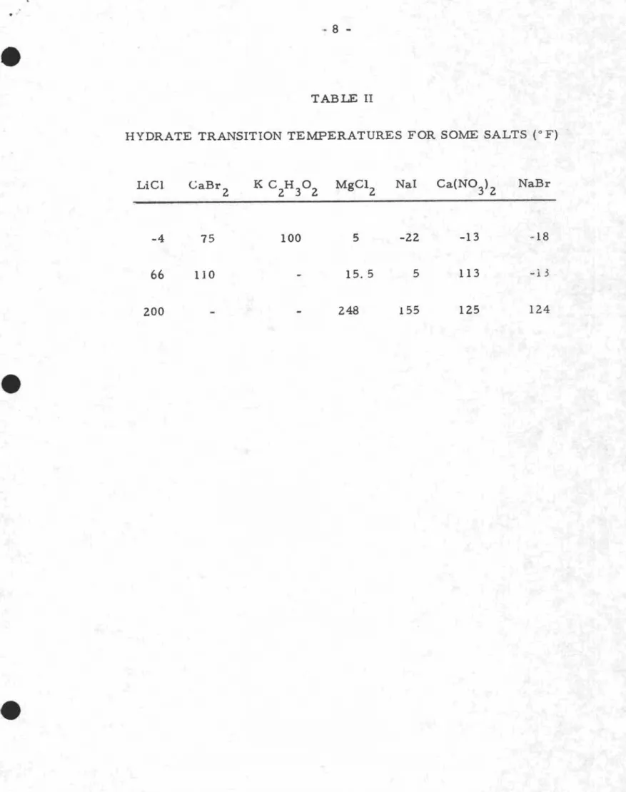
It is important to recognize that salt solutions assume different levels of hydration, depending on their temperature, and the transition from one level to another may be accompanied by a sharp change in the equilibrium. relative
humidity. Also, a salt may have two different equilibrium relative humidities
at a temperature near to the transition point. Consequently, it is pr eferable
to avoid their use in a temperature region within 5 or 10 degrees Fahrenheit
of the transition value. Hydrate transition temperatures for a number of
salts are shown in Table II.
CALIBRATION FACILITIES AT THE NATIONAL RESEARCH COUNCIL The primary calibration facility at the Prairie Regional Station, National Research Council, Saskatoon, is a two-temperature,
recirculation-type atmosphere producer. A recirculated stream of air is saturated with
respect to water or ice at one temperature, and brought to a higher
temperature before entering a calibration chamber. The temperatures and
pressures in the saturator and calibration chamber are accurately controlled
and measured to determine the air condition in the calibration chamber. An
accuracy of the order of ±0.20/0 R. H. at low humidities, and of ±0 40/0 at high humidities, is obtained.
The operating specifications of the unit are as follows: Dry bulb temperature range
Dewpoint temperature range
Capacity - 20 sensor s
O°F to 100°F
_30° F to 75° F
Sensors to be calibrated are normally precondition",j overnight in
the calibration chamber. They are then exposed to a series of conditions at
fixed dry bulb temperature, involving five relative humidity levels of increasing humidity, and five of decreasing humidity.
•
The secondary calibration unit at the Station is a flow -through, two- 5 -pressure system, having a cali'Qration tolerance of±O.
5% R. H., but with a higher dewpoint and dry bulb temperature capability. In operation, air issa.urated at atmospheric pressure and expanded to a calibration chamber at the same temperature but at lower pressure to provide the_ required relative humidity. The same general procedure in calibrating sensor s is followed.
The operating specifications for the unit are as follows: Dry bulb temperature range 32°F to 150° F
Dewpoint temperature range 32°F to l50°F Capacity - 3 sensors (to be increased to 5)
Calibration information is provided in tabular form showing the observed relationship between relative humidity and electrical resistance for each dry bulb temperature. Electrical resistance values only are given, since the microampere vs. resistance characteristics are not necessarily the same for all instruments. Calibration of a particular instrument in terms of electrical resistance is normally the responsibility of the user.
INSTRUCTIONS FOR SUBMISSION OF SENSORS FOR CALIBRATION TO THE NATIONAL RESEARCH COUNCIL
1. Completed application for test Form NRC 32 (available on request) listing the type and number of sensors to be calibrated and the temperature(s) at which calibration is desired, must be submitted to:
Mr. G. O. Handegord, Head, Prairie Regional Station, Division of Building Research, National Research Council, Saskatoon, Saskatchewan.
2. Following receipt of the application, a shipping container with the
appropriate number of sensor vials will be sent to the applicant for shipment of the sensor( s) to:
The Prairie Regional Station, Division of Building Research, National Research Council, Saskatoon, Saskatchewan.
3. Upon completion of calibration, the sensor( s) will be returned to the sender in the shipping vials for storage and future shipment for recalibration when ·.tequired.
- - -
6
-A. Calibration at a single エセュー・イ。エオイ・ throughout a resistance range of approximately 0.1 to 10 megohms. Calibration will be done at at least five different relative humidities.
(1) Temperature range 0 to 800 F (dewpoint teplperature down
to _300
F). The primary calibration facility will be used. I cell - $40.00, plus $2.00 for each additional cell in
the same humidity range, up to a totfl.l of 20 cells. (2) For temperatures above this range, a secondary
cali-bration facility may be used, and the charges will be as follows:
I cell - $40.00, plus $2.00 for each additional cell in the same range, up to a total of 5 cells.
B. Calibration at a second temperature:
Same as A(1) and A(2), except $20.00 for first cell. C. Calibration at a single temperature and humidity:
Same as A(1) and A(2), except $20.00 for first cell and $1. 00 for each additional cell.
If cells are damaged during calibration, they will be replaced by cells of equivalent value with as little delay as possible.
e
e
e
.,
TABLE 1
EQUILIBRIUM RELATIVE HUMIDITIES FOR SOME SALT SOLUTIONS
Temp. of lゥcQセG CaBr セL K C H
° ':'
l'v1gC 1 ':' NaI ':' Ca(NO ) セL NaBr':' CuC12 NH4C I':' KN03 K2S04 2 2 3 2 2 3 2 + 0 17.5 29 5 27. 33. 48.
-
69.5 68. 5 +10 16.5 28. 26. 5 33. 5 47 70. 68. 68. 5 83. 5 +20 15. 5 26 5 26. 33. 5 46. 67.5 66.5 68. 5 82. 5 +30 15. 25. 25. 33.5 45. 65. 64. 5 68. 5 82. 98. 99. 40 14. 23.5 24.5 33.5 44. 62. 5 63. 68.5 81. 96. 5 98. 5 50 13. 21. 5 24. 33. 5 42. 5 59. 5 61. 5 68.5 80. 95.5 98. -.] 60 12. 20. 23.5 33. 41. 56. 5 60. 68. 5 79. 5 94. 5 97.4 70 11. 2 18. 22. 5 33. 39.5 53. 58. 5 68. 5 78. 5 93 97. 80 11. 2-
22. 32. 5 37.5 50. 57. 68. 5 77.5 91. 5 97. 90-
-
-
32. 5 36. 46. 5 55. 5 68.5 76. 5 90. 96. 5+ The relative humidities at subfreezing temperatures are referred to subcooled water.
..
8
-TABLE II
HYDRATE TRANSITION TEMPERATURES FOR SOME SALTS (0F)
Lie}
-4 CaBr 2 75 100 5 -22 -13 -1866
200 110 15.5 248 5 155 113 125 -13 124v
,
..
9
-SUPPLEMENTARY NOTE TO DBR/NRC TECHNICAL NOTE 421, USE AND CALIBRATION OF DUNMORE-TYPE ELECTRICAL HUMIDITY SENSORS by C. P. Hedlin
WHEN CALIBRATION IS REQUIRED
Technical Note 421 describes NRC calibration facilities and cost of calibration services, and discusses pertinent characteristics of sensors in
relation to use and calibration. Some further comment is required as the cost of calibrating a sensor may be much greater than the cost of a new one. Several sensor s having the same range can be calibrated together at little increase in cost over that for a single one, but the cost of calibrating a single sensor may be five or more times its original cost. The user must consider carefully when it is appropriate to have sensors calibrated.
Manufacturers offer sensors having a stated accuracy of ± 1 or ± li%. It is not reasonable to expect that the manufacturer can guarantee absolutely that the accuracy of every sensor sold will fall within his stated tolerances over the full range of conditions. He must in the nature of things establish some acceptably low probability of failure which he maintains through quality control.
When sensors are suspect as to calibration because of use or age it will obviously be more economical to replace them with new sensors obtained from the manufacturer rather than to pay the higher cost of calibrating. Sensors which are suspect may also be checked against a new sensor or against some other reference, and re -used if there is no reason to suspect that they have shifted seriously in calibration or if it appear s that a correction can be made. When, however, the user cannot accept the probability that the accuracy is less than that stated by the manufacturer, or when improved accuracy must be
obtained, or when he must have a certificate of calibration from an independent laboratory he has no choice but to have a calibration carried out.