Publisher’s version / Version de l'éditeur:
Vous avez des questions? Nous pouvons vous aider. Pour communiquer directement avec un auteur, consultez la première page de la revue dans laquelle son article a été publié afin de trouver ses coordonnées. Si vous n’arrivez pas à les repérer, communiquez avec nous à [email protected].
Questions? Contact the NRC Publications Archive team at
[email protected]. If you wish to email the authors directly, please see the first page of the publication for their contact information.
https://publications-cnrc.canada.ca/fra/droits
L’accès à ce site Web et l’utilisation de son contenu sont assujettis aux conditions présentées dans le site
LISEZ CES CONDITIONS ATTENTIVEMENT AVANT D’UTILISER CE SITE WEB.
Report (National Research Council of Canada. Division of Building Research); no. DBR-R-62, 1955-12-01
READ THESE TERMS AND CONDITIONS CAREFULLY BEFORE USING THIS WEBSITE. https://nrc-publications.canada.ca/eng/copyright
NRC Publications Archive Record / Notice des Archives des publications du CNRC :
https://nrc-publications.canada.ca/eng/view/object/?id=4ac8342b-d52e-43e3-8e22-de5209549859 https://publications-cnrc.canada.ca/fra/voir/objet/?id=4ac8342b-d52e-43e3-8e22-de5209549859
Access and use of this website and the material on it are subject to the Terms and Conditions set forth at
Structural Testing of an Experimental House
DIVISION OF BUILDING RESEARCH STRUCTURAL TESTING OF AN EXPERIMENTAL HOUSE by D.B. Dorey Report No" 62 of the
Division of Building Research
Ottawa December
1955
Housing research continues to occupy a vital position in the planning of all the work within the Division of
Building Research. Early studies in this field suggested that there was a good deal yet to be learned about the
strength of the frame of the standard Canadian house. This report is a first statement on the work done on this problem.
The author was a member of the Building Design Section when he prepared this report, the project being a major one of that Section, under the leadership of its Head,
W.R. Schriever. Mr. Dorey has now been transferred to the Atlantic Regional Station of the Division, of which he is
in charge, but his interest in the sUbject matter of this report continues.
Tne testing of the house as described in this report was a pioneer effort on the part of the Division. Advantage was taken of information in the few reports available dealing with similar test work. It was realized, however, that to a
large extent the work would be exploratory.
The Division has learned a great deal from the work described which will form the basis of further studies in the same direction. The report is presented in this form, and with full details, for the benefit of those specially interested. A paper summarizing the more significant aspects of the work is being prepared and it is hoped that it may be presented at a meeting of the ASTM late in
1956.
R.F. Legget, Director.
Ottawa
D.B. Dorey
Unlike industrial bUildings and other larger structures, a house does not lend itself to the refinements in design
afforded by engineering analysis. For this reason the design for strength and rigidity in house construction in Canada, as well as in other countries with similar climatic loads, has depended largely on local building regulations and past experience in the art of home construction.
It is generally believed that most established methods of house construction have an inherent factor of overdesign and that substantial economies could be effected if a means could be found of evaluating the ウエセオ」エオイ。ャ aspects of a completed house. This need for a means of evaluating the structural sufficiency of a house design has become even more pronounced with the introduction of new materials and new methods of combining both old and new materials in house construction. In" some cases, a new method of construction
can be compared structurally with older and established methods with some success, but in other cases there is no direct basis
of comparison. Even when a comparison is possible, there is always the factor of overdesign to be considered in the
economics of the construction. The structural assessment of
ィセオウ・ designs must, therefore, rely upon information obtained through a program of full-scale house testing.
The ヲッイュ。セゥッョ of the Division of Building Research in
1947
marked the beginning of organized bUilding research in Canada on a national basis. As a special service to the bUilding industry and to Central Mortgage and HousingCorporation, the Division works on many problems that require special facilities and trained personnel. Local building regulations are often based on, or adopted from, the National Building Code, the continuous revision of which is the
responsibility of the Associate Committee on the National Building Code, technical work for which is carried out by the Division. With these obligations and needs to the fore, the Division, shortly after its formation, initiated a
research ーイッェセ」エ on the structural testing of full-scale house frame::?
Work on this project began by making a literature survey of pertinent work by other research organizations. Although the results of many tests were reviewed, only those dealing with tests on complete dwelling assemblies will be mentioned in this report.
In Great Britain a special Interdepartmental Committee on House Building, The Burt Committee, was appointed in
1942
to pool and summarize the available knowledge on unconventional methods of house bUilding and on house bUilding in general. The findings of the Burt Committee were published in Post-War BUilding Studies, Nos. 1 and
23.
At the request of thisCommittee the British Building Research Station examined the functional efficiency of a considerable number of house
types with regard to strength and stability and other relevent properties.
In South Africa, again as a means of furnishing urgently needed information, the National Building Research Institute conducted a program of performance tests on native houses for the National Housing and Planning Commission. The structural behaviour of each house under loads was compared with that of traditional houses and only the expected loads, with a load factor, were applied during the tests.
In
the United States, the U.S. Naval Civil Engineer-ing Research and Evaluation Laboratory at Port Hueneme,California, have conducted several full-scale loading tests on prefabricated Service structures. Each structure is
subjected to a loading test as a direct means of determining whether the structure meets the Service structural require-ments under simulated live loads.
2. DBR EXPERIMENTAL HOUSE
In
1947
the Division of Building Research and the Central mッセエァ。ァ・ and Housing Corporation agreed on the construction of two experimental houses on the grounds of the National Research Council Laboratories, Montreal Road, for testing purposes in a number of fields of interest and for use in developing structural testing techniques.Plans for Experimental Houses Nos. 1 and 2 were drawn up by CMHC in consultation with the Division and
construction of the units was carried out by Wartime Housing Limited (then a subsidiary of CMHC). Construction of these units was completed by the end of June,
1948 (1).
The experimental house chosen for the structural test is a basementless, one-storey, wood-frame dwelling
36
feet8
inches long by24
feet4
inches wide. It has threebedrooms, a living room, a kitchen, a bathroom, and a utility room. A floor plan and cross-section of this unit are shown in Figs. 1 and 2 respectively.
The foundation walls, constructed of concrete blocks, extend to a depth of 3 or 4 feet below grade to bed-rock. Approximately one-half of the crawl space beneath the house was excavated to bed-rock. A doorway in the foundation wall serves as an access to the crawl space. The 2- by 6-inch sills were fastened to the top of the foundation wall with anchor bolts.
Floor joists, 2- by 8-inches placed on 16-inch centres, span each half width of the house and are supported at the
centre of the house by a wood beam made up from 2- by lO-inch planks, running lengthwise through the centre of the house. This supporting beam is supported in turn by the end walls of the concrete block foundation and at approximately the third points of its span.
Diagonal subflooring, 13/16 inch thick, was put down over the floor joists. Hardwood flooring (a mixture of birch and maple), 3/4 inch thick, was laid in the bedrooms, living room, and hallway. Asphalt tile was laid in the kitchen and utility room.
The exterior walls were constructed of 2- by 4-inch wood studding placed on 16-inch centres, and braced by 1- by 4-inch diagonal wood members let into the studs at each corner of the セッオウ・N Horizontal wood members, 2- by 4-inches, were placei between the studs at the mid-height of the studs.
'I'ne scudding was covered on the outside with 12-pound asphalt-saturated felt paper, over which interlocking aluminum siding, 6-7/8 inches in width, was nailed to the studs. This feature of the exterior wall is shown in Fig.3. Figure 4 shows part of the unclad framing and the aluminum siding being applied to Lue \;a.il studs over the saturated felt on the rear wall of the house.
An important research aspect associated with the
construction of the exterior walls of this unit is the omission of any form of exterior sheathing, During the planning of this house it was considered that an excellent opportunity existed for making a study of the strength and stability of such a dwelling unit when the exterior sheathing is omitted. It was decided, therefore, that the exterior walls should be constructed without using exterior sheathing, which normally contributes
to the strength and stiffness of conventional exterior wall construction.
The roof framing consists of a ri'1ge board and 2- by 4-inch rafters placed on 16-4-inch centres キゥセィ 1- by 4-inch collar ties for each pair of rafters, The collar ties were ヲ。ウセ・ョ・、
to each other at midspan by a 1- by 4-inch longitudinal member nailed to their underside. Battens, 1- by 6-inches, were
naile1 to the top of the rafters at approximately 6-inch
intervals, and were covered by 12-pound asphalt-saturated felt. V-crimp aluminum roofing, 30 inches wide, and running the full
length of the rafters, was applied parallel to the rafters,
over the asphalt-saturated felt. The aluminum sheets overlap
one another
7
inches and are double V-crimped at the joints. The slope of the roof is6
inches vertically to 12 inches horizontally.The ceiling construction consists of 2- by 6-inch ceiling joists, spanning across the house and supported near the centre of the house by a partition wall. No attempt was made during construction to fasten each ceiling joist securely to the lower end of each corresponding rafter at the exterior Viall plates, and at some points the celing joists were
approximately 2 inches from the nearest rafter. Gypsum board
3/8··inch
thick, was placed on the underside of the joist as interior finish.A central Load-ibear-Lng partition, running parallel with the side walls, was constructed of 2- by 4-inch studs placed on 16-inch centres. Fibreboard セMゥョ」ィ thick was put on both sides of this partition, followed by
3/8-inch
gypsum board applied over the fibreboard. All other partitions were framed in the same way, except for the walls and closets of one bedroom, but do not have the セMゥョ」ィ fibreboard under the gypsum board.A second experimental feature of this house was the construction of the three partition walls and the closets of the bedroom just mentioned. Sheets of gypsum board, 4 by 8 feet, were keyed into grooved strips of wood which were fastened to the floor and ceiling. Adjacent sheets were fastened together at the joints with metal clips. Plaster made from カ・セョゥ」オャゥエ・ instead of sand for the rough coat, in the proportion of one bag of vermiculite to three bags of hard-wall plaster, wae applied to both sides of the gypsum board to make a solid wall 2 inches thick. Corners were reinforced and protected by strips of wood and where closet walls were of solld construction, shelves and clothes poles were supported by wooden hangers nailed to the ceiling joists.
Aluminum door and wLndow units were installed and
3.
PURPOSE AND SCOPE OF STRUCTURAL TESTSThe field of structural testing is a very broad sUbject. It is therefore necessary when dealing with any specific test, to outline the principal objectives, and to limit the scope of the investigation. In even the simplest structural tests, the testing method and techniques are important. The development of testing methods and techniques was therefore a necessary part of this investigation.
The purpose of the structural test on the DBR experimental house was twofold:
(a) To obtain information on the strength and stiffness of a full-scale single-storey house from which exterior sheathing had been omittedj
(b) To obtain information which will assist with the
development of full-scale testing methods and procedures for evaluating the relative strength of house frames.
The various structural tests which may be conducted on elements, components, and complete assemblies of domestic dwellings are all inter-related. The degree of
inter-relationship depends upon the type of construction. Structural tests on individual elements such as studs, joists or rafters or components such as floors, walls, or roofs, will reveal the strength and stiffness of the specimens, but will not establish an accurate indication of the strength and rigidity of a
dwelling assembled from these elements and components. It is for this reason and because of the indeterminate nature of house construction that full-scale dwellings must be tested if a useful attempt is to be made in correlating the results of such investigations. 'rhe testing of reduced-scale models would be difficult because of scale effects, and also with regard to nailing.
Apart from correlating the results of tests, there is the important question of performance requirements which a full-scale dwelling must fulfil under loading. Under design loadings, for instance, deformations in the load-supporting members may, and often do, cause unsightly cracks to appear in walls and ceilings. The danger of such damage appearing under load was especlally prevalent in the experimental house tested, as it had no exterior sheathing. The aim, therefore, in this structural test was to apply the design loadings of the
1953
edition of the National Building Code for wind and snow loadings, and to make observations on deformations, and other relevent phenomena, during the various loading phases.Since it was not the intention of the Division to damage the test house extensively, loading would only be carried to a point of relatively minor damage.
4. PREPARATIONS FOR TESTING EXPERIMENTAL HOUSE 4.1 Choice of a Loading System
One of the problems in the planning for this test was the selection of a method by which the necessary loads might be applied to the test house. A review of the methQds used by other research organizations revealed two possible methods. The first method makes use of a ウケウエセjィ of steel cables that are anchored to the ground at one end and are directed over columns through a loading mechanism and a load-measuring device to the load-distributing bearing pads on the roof or side wall. The second method makes \.lse of a reaction frame-work over the test house, inward and outward thrusts being applied by double-acting hydraulic rams.
The first method has the advantage of simplicity of assembly but is not readily adaptable for applying outward thrusts to moderately sloping roof surfaces. Undesirable features of this method are: openings are also required in walls, roof, ceilings, and floors to accommodate the cables; the loading cannot normally be controlled at one central position, as some of the loading mechanism operators are inside while others are outside of the test house. This
method is adequate for certain structural tests but is limited in its application.
The second method, which uses a reaction framework is much more complicated to design and assemble but the extra planning is justified if the facilities are available. With a rigid reaction framework spanning the test house simultaneous inward or outward thrusts may be applied and controlled from a .Lセ・ョエイ。ャ position without altering the test house in any way .
\ .
After careful thought had been given to both methods, and since the Division had an available stock of Bailey
bridging components which could easily be adapted to use, it was decided that the reaction framework method should be used for this test.
Another question which arose during the planning of this test was the choice of a load distribution system on the side walls and roof. Maximum shears and bending moments could be developed in the house components, or a system of loading
could be used which would approach uniform loading on the structure as a whole and produce the over-all affect of wind 'or snow loads. This question was discussed at length and it was decided to distribute the loading as closely as possible to uniform loading condit.ions to produce the overall effect of the loadings which would be assumeo in the design. The roof and side wall loading distribution as shown in Fig, 8 was セィ・イ・ヲッイ・ adopted.
T,ligure Nセ c..1so shows that the loading system was
designed for the various loads to applied at right angles to the roof and side walls. The system adopted represents the normal wind loading conditions but does not represent the correct system of loading for snow loading which is a certain magnitude of loading per square foot of horizontally projected area. To represent snow loading, the roof loads should be applied vert.! ca lLy • Since, however, the test house did not hcive exterlor sheathing to contribute strength against
racking loads, it was thought that the wind loads would have the greatest influence on the interior finishes. As the additional work and expense involved in providing a loading system that could be used to apply loads either vertically or at right angles to the roof キッセャ、 be considerable, it was decided to provide a ウケウエ・セ that would apply loads at right angles to the rouf only ahd disregard the component of the snow loading parallel with the slope of the roof.
4.2 Reaction Framework and Loading Members
Plans for a reaction framework spanning over the top of the test house, composed mainly of Bailey bridging, with specially designed components, were completed auring the third quarter of 1953, and tenders were イ・アオセウエ・、 on the fabrication of the special components during the fourth quarter of the same year. Quotations were received from three steel
fabricating companies for supplying the steel and fabricating the items. The contract for this phase of the work was
awarded and delivery was made on April 6, 1954. Some welding work was done at a later date, by the same company on the
Bailey transoms, which were stockpiled on the National Research Council property.
Special ヲッオョ、。セゥッョ pads to accommodate the Bailey
reaction framework were fabricated by Plant Engineering Services of the National Research Council. Excavations were made by a group of N.R.C. workmen at the front and the rear of the test house, to a depth of 3 feet below the top of the foundation wall, and of sufficient length and width to take two foundation pads on each side of the house. Each excavation was partially
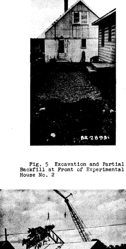
backfilled with crushed stone as shown in Fig.5. Twelve railway ties were embedded and levelled in each excavation. The foundation pads were each lifted by a tripod hoist truck, transported, and lowered down in position on the railway ties. Each foundation pad was then anchored to the six railway ties, after which crushed stone was placed level with the top of the 12- by l2-inch bedlogs of the foundation pads.
During the installation of the foundation pads, tenders were requested on the erection of the steelwork over the test house. Two quotations were received, and in view of the work done on the fabrication of the steelwork, that of the company which did the fabricating was selected. Erection of the
steelwork began on the morning of June 6, 1954 and was completed on the afternoon of June 11, 1954. Figures 6 and 7 show two different stages of the erection.
As work progressed on the erection of the steelwork, worKrflen from Plant Engineering Services prepared the test house for the structural investigation and erected a fence around the test site to discourage children and unauthorized personnel from interfering with the test site work.
All the aluminum sash windows in the side walls were removed and temporarily replaced by plywood panels, fitted to the window sash grooves. Triangular-shaped plaster tell-tales, t-inch thick, were put in all upper interior corners where a partition wall or end wall intersected a side wall and are numbered as shown in Fig.I. Each tell-tale was bonded to a prepared area of the gypsum board on each plane to
indicate relative movement between the three intersecting planes under loading.
Workmen from Plant Engineering SerVices prepared and mounted the loading bearing pads on the side walls and roof.
Hardwood members, 2 by
6
inches, running the full length of each pad, were bolted to the 4-inch I-beams. The hardwood members were then cut along their bearing faces to fit theーイッセャャ・ of the roof, for each position on the roof. The side wall load-bearing pads did not have to be profiled for special positions. Sponge rubber, l/8-inch thick, was bonded to the surface of the hardwood at each point of contact with the roof. The purpose of the sponge rubber was to provied a compressible
medi.uru uetween the two surfaces so that under pressure, during
bonding, the maximum area of contact might be effected. The roof was divided into sixteen equal tributary areas of loading as indicated in Fig.8 and each load-bearing pad was adjusted to its correct position and bonded to the aluminum sheeting with 113M Adhesive and Coating" compound so that both an upward and a downward force might be applied to the tributary area.
Each side wall was divided into eight equal tributary areas of loading again as indicated in Fig.8, and softwood strapping, t-inch by 4t-inches was nailed over the aluminum siding as furring strips for the load-bearing pads. The side wall load-bearing pads were fastened to each stud or studs they. crossed with two turns of No. 9 wire, above and be Low the I-beam section. The wire was drawn taut through the holes in the hardwood member, furring strips, and wall by wedges on the inside surface of the interior finish. The wedges were necessary because of the flexibility of the aluminum siding. At window openings, the load-bearing pads were fastened through the furring strips and plywood panels
in the same manner to distribute the loads to the window frames. Each pair of load-bearing pads on the side walls and roof were connected at their mid-point to a cross-whiffletree by.a universal joint. This cross-whiffletree was connected by a pin joint at its centre point to a tension and compression strut. Each of the twenty-four tension and compression struts were restricted to unidirectional movement at right angles to the plane being loaded. Bailey transoms, U-bolted to the
outside of the Bailey panel chords, passing between the 3-inch channels of the tension and compression struts, and angle-iron guides'U-bolted to each transom, restricted the movement of the tension and compression struts to a ヲoセGャ。イ、 and reverse movement so that tension and compression loaqs might be applied to each tributary area. Batten plates on the struts, and lugs welded to the transoms, provided pin-jointed connections for the hydraulic rams,wpich were later mounted between the chanrels of the tension ano. compression struts. The details
jUbt described are illustrated in Fig.9, which shows a general view of the test assembly.
The ballast bins, shown at the base of the reaction framework in Fig.9 were construsted to confine crushed stone which was required to stabilize the reaction framework against uplift and lateral movements. Approximately thirty-two cubic yards of crushed stone were required as ballast. Standard Bailey sway-braces with special end connections were bolted together in lengths of two's to act as tie rods across the foundation pads through the foundation walls of the house. 4.3 Deflection Measuring Apparatus
As work was progressing on the installation of testing equipment around the test house, a system of pUlleys and wires was being installed inside the test house to measure the
The chimney, which is near the centre of the house, was taken down to a point approximately one and one-half feet below the ridge board in the attic. All the material wittin 4 inches of the outside of the chimney was removed from the top to the concrete foundation in セィ・ crawl space on all four sides so that, when used as a large dial stand from which the interior deflection apparatus was suspended, it would be
unaffected by movements in the house when the loads were applied, Piano wire, 0.010 inch in diameter, running over a system of
2i
inch low-friction aircraft pulleys, was installed to register horizontal and vertical movements on four deformation planes, one at each of the third points in the interior and one at each end wall on the exterior as shown in Fig.lO.Wires to register horizontal movements in the interior planes of deformation were attached at the base, mid-height, and at the ceiling level on the side walls. Similar wires to register horizontal movements in the roof were attached at the centre span of a pair of opposite rafters and at the ridge board on each interior plane.
Wires to register vertical movements or the interior planes of deformation were attached at ceiling level on the side walls and at the centre span of a pair of opposite rafters and at the ridge board, making a total of fourteen pains セ which deflections could be measured on each of the two interior planes. .
Wires to indicate horizontal movements in each of the end wall planes were attached to the floor, eave, and ridge levels. Two additional \'Tires were installed on each of the end-wall planes to indicate vertical and endwise movement at the r-Ldge vboar-d level of the test house. TvlO wires to indicate if the deflection apparatus had been disturbed, and to indicate the effects of temperature on the battery of wires, were
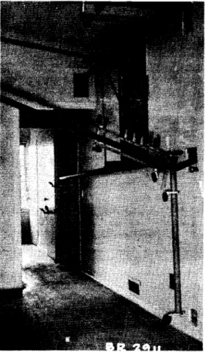
。セエ。」ィ・、 to the interior セオ}ャ・ケ supporting framework. All the wires leading from the various points of interest in the house were concentrated by the pulley system inside the house so that they could be brought through one window opening in the end wall of the house to terminate, and be tensioned equally by identical recording weights, on the deflection board in the instrQment house. Figure 11 is a view of the deflection apparatus io the living room and hall-way, and shows the way Ln which the system was attached to the chimney through the larger opening made in the partition wLII. Fi.gure 12 shows the termination of each of the forty-four
Deflection pulleys and wires were mounted on three tubular steel columns on which to mount the set in concrete piers in the ground at each end of the test house. It was necessary on the end walls, as well as in the interior of
the house, to mount the deflection apparatus on an independent framework.
A concrete slab,
6
by8
feet, was placed5
feet from the west end, and on the centre line, of the test house. This slab was designed to provide a rigid foundation for theinstrillnent house which housed the deflection board, hydraulic console unit, the power supply transformers, and the four
:_l1s01e operators. The instrument house was designed so
セィ。エ it could be disassembled in panels of convenient sizes for handling. Shutters, hinged at their lower edge, were made for the openings in the end next to the test house and on the sides. Double doors to accommodate the testing
apparatus, which was later moved into the instrument house, were put in the end farthest away from the test house. All the deflection wires were brought through the opening nearest to the test house. A general view of the instrument house is shown in Fig.13.
4.4
Hydraulic Loading EquipmentThe amount of hydraulic equipment required for this test included twenty-four lightweight hydraulic rams, air
。」」Gセオャ。エッイL console unit, and special hydraulic lines and fittings. Lacking this special equipment, the Division was fortunate in obtaining the co-operation of the Structures Laboratory of the Division of Mechanical Engineering in the loan of their equipment for this first full-scale loading
test. •
The twenty-four hydraulic rams were calibrated, usLng a hydr-au l tc hand pump and a standard pressure gauge, in th8 Divisionis 60,OOO-pound testing machine, prior to their being mounted in the tension and compression struts of the testing framework. Each hydraulic ram was calibrated fer hydraulic pressures ranging from 0 p.s.i. to 2,000 p.s.i, The connections to the hydraulic rams on the struts and
Bailey transoms were designed so that the direction of the force exerted by the hydraulic rams could be reversed, thus making it possible to apyly either a push or a pull to the area of loading,
Four pressure channels, each operating at a different
rams on the four surfaces of the test house. The distribution of the hydraulic rams on the four loading surfaces of the test house consisted of four rams of equal thrust capacity on each of the side walls, and eight of equal thrust capacity on each of the two roof slopes. Each of the four pressure channels was connected tc a pressure gauge and operating valves on the hydraulic com.';'!e unit in the instrument house.
An air accumulator which could be charged with a booster
ーセー to pressures in accord with the イ・アオゥイ・ュセョエウ of the hydraulic rams was connected to the fifth pressure channel outlet on the console unit to maintain pressures in the other four channels during loading. A standard pressure gauge was coupled to the hydraulic pressure channel connecting the accumulator to the console unit to indicate the operating pressure of the accumulator at any particular time during
the test. Each hydraulic pressure gauge was calibrated before being used in the loading circuits.
5.
STRUCTURAL TESTING OF EXPERIMENTAL HOUSEThe sequence of loading phases decided on for this test was to begin with wind loads, followed by a combination cf snow load plus wind loads, and finally to complete the investigation with the snow loads, i.e., the order of loading would be from minimum to maximum conditions as follows:
(a) Wind loads - internal suctionj (b) Wind loads - internal pressurej
(c) One-half des1.gr: snow load plus wind loads;
(d) Snow 1 oads.
According to the
1953
edition of the National Building Code, go miles per hour is the design wind velocity for the Ottawa area and 120 miles per hour is the highest wind velocity that woul; ;«,1: セェャセO be encountered in the populated areas of Cariada , 1: "' _ L d , therefore, that the wind loads wouldfirst be carried tu the design velocity of go miles per hour and maintained for one hour, then released and re-applied up to a velocity of 120 miles per hour for both an internal' suct ion and an intern9.1 pre ssure condit ion.
There was some doubt as to what percentage of the design snow loading should be used for the combined loading condition
which is not stipulated in the National Building Code
(1953).
After careful consideration, it was decided that the maximum amount of' snow which might be expected to remain on the roof under high wind velocities and favourable conditions would be approximately 50 per cent of the design snow loading. For the 」ッュ「ゥョ・セ loading phase, one-half of the design snowloading was therefore used.
The magnitude of the design snow loading was arrived at by direct computation from the information given in the National Building Code
(1953).
The computed loads appearing in the loading schedule are the components of the vertical loads acting at right angles to the slope of the roof.Preparations for the testing of the experimental house were completed on August 27,
1954
and the first phase of loading began on September 1, 1954.501
Wind Loads - Internal Suction5.1.1
Wind velocities 70 to 90 miles per hourAfter the air cylinders of the accumulator were charged with air to pressures varying from 450 p.s.i. to 800 p.s.i., the wind loads given in Table I were applied in increments of
10 m.p.h. wind velocity, beginning at 70 m.p.h. wind velocity and ending at the design wind velocity of go m.p.h. for the ottawa area. Loads corresponding to wind velocities of 70 and 80 m.p.h. were maintained for a period of one-half hour and the design loads for a wind velocity of go m.p.h. were
maintained for a period of one hour. Deformations were
recorded on the deflection chart in the instrument house by one of the four console operators before and after each
increment of loading and after the loads were removed.
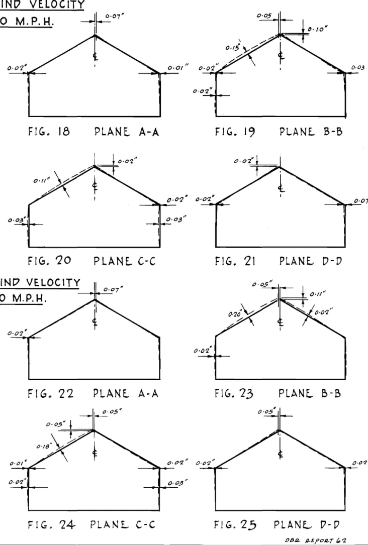
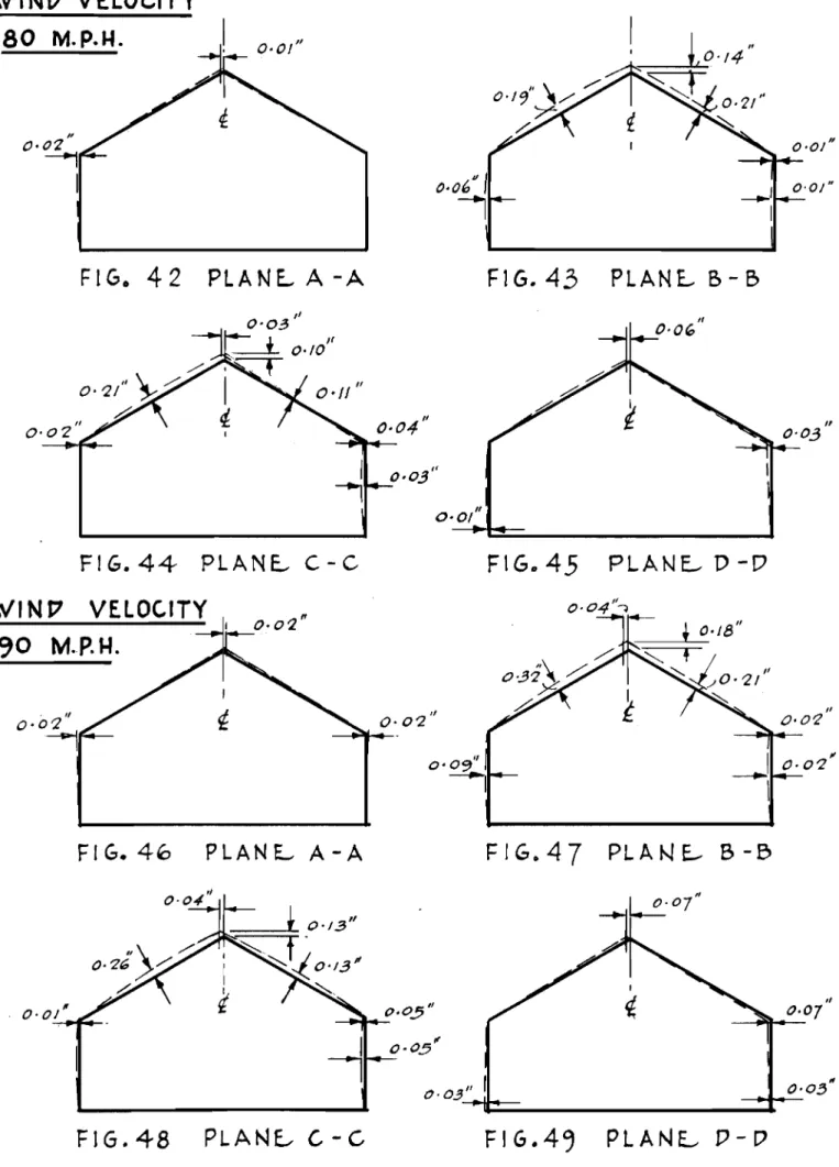
Correspondingly, a visual inspection was made of each of the thirteen plaster tell-tales before and after each loading increment to see if any cracks had developed. No cracks appeared, however, during this loading phase. Deformations that resulted from the loads applied to the test house in this first phase of loading are shown in Figs. 14 to 25. 5.1.2 Wind velocities 90 to 120 miles per hour
The next loading phase was a continuation of the
loading schedule given in Table I up to, and including, loads c0rresponding to a wind velocity of 120 m.p.h. Each wind load was sustained for a perion of one hour after a go m.p.h. wind velocity loading was reached.
Loading equivalent to a go m.p.h.wind velocity was applied in two stages. Console pressures were raised on all four channels from zero to one-half those required for a
go m.p.h. wind velocity simultaneously, and after all pressures became stable, a further increase was made until pressures
equivalent to a go m.p.h. wind velocity were reached. An
inspection of the interior of the house revealed a large crack in tell-tale No.5 soon after this loading had been 。ーーャゥ・、セ
Toward the end of the one-hour period of sustained loading, a second Jarge crack became visible in tell-tale No.9. All
loads were then increased to simulate the affect of a 100 m.p.h. wind velocity. At the end of the one-hour period of susttined
loading there were no further cracks visible in the tell-tales. Loads equivalent to a wind velocity of 110 m.p.h. were then applied and maintained for a period of one hour. Further inspections of the tell-tales did not reveal any additional cracking under this loading. The final loading equivalent to a wind velocity of 120 m.p.h. acting on the test house was then applied and maintained for one hour. During this period of sustained loading, large cracks appeared in two more tell-tales, Nos. 6 and 10. The deformations resulting from this phase of loading are shown in Figs.
26
and37.
At theend of the one-hour period of sustained loading equivalent to a wind velocity of 120 m.p.h., all pressures on the console were released simultaneously in increments of one-third of the maximum pressures reached on each of the four channels,
Unfortunately, further testing operations were delayed for a period of approximately one week. This delay was caused by a period of rainy weather and by a breakdown in the bond between some of the beartng pads and the aluminum roofing. In the latter case, the pUlling away of the bearing pads di.scouraged any further Lvpe of avoiding extensive damage to the aluminum sheeting on the roof. After several unsuccessful attempts to rebond successive bearings pads to the flexible aluminurn sheeting, and since the failure of one bonded pad meant a hold-up of the test until repairs were made, it was decided that each roof bearing pad should be fastened to the roof in the same manner as the bearing pads were fastened to the side walls, but with the wedges omitted. Holes were drilled through the roof at each point where a bearing pad crossed a rafter and two turns of No.9 wire were drawn taut around the rafter and the bearing pad, Over the wall plates, where it was impossible to use wire, lag screws were put down through the bear5.ng pads and roof into the rafters. Caulking compolli1d was applied to the bearing pads and roof at points where water nlight find its'way through to the interior.
5.2 Wind Loads - Internal Pressure
5.2.1 Wind velocities 70 to 90 miles per hour
When work on the roofing bearing pads was finished, the test was resumed, but with loads corresponding to a different wind loading condition, that producing internal
pressure (windows open on windward side only). This condition is more severe as it produces greater loads except on the
windward wall. The loads which were applied for this condition are given in Table II.
Console pressures were tncreased simultaneously to values giving loads cn the test house equivalent to a wind velocity of 70 m.p.h. After the console pressures became
stable, this loading was maintained for a period of 20 minutes. During this period of sustained loading, no further cracks
were visible in the tell-tales. Allillads were then increased to values simulating the effect ッセ a wind velocity of 80 m.p.h. This loading was also sustained for a period of twenty minutes, during which time a new crack became visible in tell-tale
No.6. At the end of this period of sustained loading all
loads were increased to simulate the effect of a wind velocity of go m.p.h. This loading, which is the design velocity for the Ottawa area, was maintained for a period of one hour but no further cracks appeared in the plaster tell-tales. At the end of the one-hour period of sustained loading, pressures
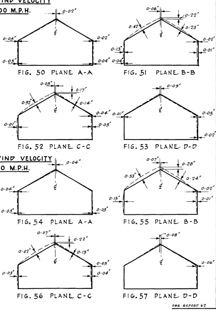
were released on the console simultaneously, and in three steps, to zero. The deformations resulting from loading phase are
ウィッセョ in Figs.
38
to49.
5.2.2 Wind velocities 90 to 120 miles per hour This phase of loading
schedule given in Table III. loads corresponding to a wind applied.
was a continuation of the loading Final loading was reached when velocity of 120 m.p.h. had been As before, when loads ウゥュセャ。エゥョァ an internal suction condition were applied, console pressureb were raised from zero to values equivalent to a wind velocity of go m.p.h. in stages. At pressures simulating a wind velocity of 80 m.p.h., a small
crack appeared in tell-tale No.2. During the process of
increasing and maintaining loads equivalent to wind velocities of 90, 100 and 110 m.p.h., no further cracks appeared, but during the one-hour period of sustained loading for a wind velocity of 120 m.p.h., a crack which appeared in tell-tale No.5 earlier in the test, extended noticeably. At the end of the loading period, all loads were released simultaneously
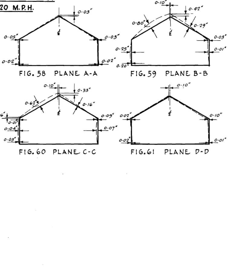
in three ウセ。ァ・ウ to zero. The deformations resulting from this phase of loading are shown in Figs. 50 to 61.
Up to this ーッセョエ in the test, the roof loads were in the form of an outward thrust at each of tne loading points.
Havi.ng ccmpl e ted the wind loading schedule, the next phase of
Loadtng in the dt r-ect Lon of increasing severity of loading
was that of a combination of wind and snow loading. Since the net result of such a combination of loading required an inward thrust on the roof .. a brief period of time was allotted for the 」ィ。セァゥョァ of the sixteen hydraulic rams acting on the roof sUlfaces. During this interlude, the plaster tell-tales were rephotographed to record the extent of cracking which
had taken place under- the applied wind loads.
5.3 One·-half Design Snow Load plus Wind. Loads
5.3.1
One-half 、・セゥァョ snow load plus wind velocitie::;70
to120 miles per hour
After the hydraulic rams had been reversed in the
teneLon and oompr-e s si on struts on the roof and photographs had
been ta.ken of the plaster tell-tales, the combined loading of
wind and snow was applied for wind velocities varying from 10 m.p.h. to 120 m.p.h. as given in Table III.
As before, all pressures were raised simultaneously
in stages until those giving combined loads equivalent to
one-ィセャエ 、・セャァョ snow loading and a wind カ・ャッセャエケ of 70 m.p.h. were
セ・。」ィ・、N Under this condition of sustained loading a small
new crack 。ーー・。イセ、 on the ceiling side of tell-tale No.4.
No
further cracking took place in the plaster tell-tales asセHG・ァオャ。ZNB Lncr-ease s of 10 mi psh , wind velocity were applied u..nt i.I
an 1'3<'}'11va lent ccnc i t Lon of a 110 m,p vh , v.;ln.d veLoc tty' was HLLセ。NZ「YLェN Unde:, t.ht.s cond tt ion of sustamed Lcading , a small new craak became カャセゥ「セN・ in tell-tale No.8. A final loading
o.f o!1e-hal.f design. snow loading plus a wind veLoci t.y of 120
m.p.!\. was r-eached witnout any further apparent cracking in the tell-tales. After being maintained for a given period of エゥュ・セ all loads were reduced simultaneously to zero in three etage s as before. The deformations resul ting from this phase of loading are shown in Figs. 62 to
85.
5.4
Snow Loadsnit? next phase of' loading consisted of applying regular
increments were applied as given percentages of the design snow loading fer the ottawa area as found in the
1953
edition of the National Building Code. The snow loading schedule for this phase of loading is shown in Table TV.During the application of the snow loading, two members from the Photogrammetry Section of the Division of Physics were ーセ・X・ョエ to measure deformations in the test house by a photogrammetrlc method. Two cameras, acting in unison, were positioned and ッセゥ・ョエ。エ・、 on the front of the test house to form a stereocamcxa, As the loading progressed, photographs were taken of the tesv house with these cameras to record the deformations produced.
When this loading phase began, the console pressures were raised un Lrcr-mLy r.n the two pressure channels actuating
tne hydraulic rams on the roof until loads equivalent to a 50 per cent snow loading were applied. After a period of s ueta Lned loading, the crack which had appeared in tell-tale No. 9 earlier in the test extended noticeably and the
deflection weights on the chart in the instrument house showed large deformatlons in comparison to previous load_ngs. At the end of one-half ィPuセL the loading was increased to
75
percent of the design snow loading. As the loading was increased from 50 to '?5 pe r ,:..?n.t snow loading many new cracks occurred in. tne tel;-tales and sounds of cracking could be heard in the house. At エ・ャャMセ。ャ・ No.9, the exterior wall and the solid p La et er' pa.r t.LtLon separated to the extent of 1/8 inch
near the ceiling and ended near the floor. After a ッョセMィ。ャヲ
hour period of sustained loading, a further increase was made to 100 per cent snow ャッ。、ゥョセN This loading, (the design snow
QiI。Hlセ⦅ョァ for t.he Ott awa area) was s uat af.ne d for approximately
one haUl' withe'uT: any T'ur-t.he r- ee r Lous damage. At the end of
セョ・ hour エセ・ loading was increased from 100 to 125 per cent of the 、セbセウョ snow leading. During this increase in loading t'urt.her- eounds of di8' r-es s wer . audible, and the increase in r.r.e de£"orma.t lr')na:ohu\A n on the del j eCGion chart indicated
t nat a ヲウNNNuNjNyGHセ l,.j,::>:'ld s oon occur, BNLNセ ter- one-half hour had
セャ。ーウ・、N エィセ sセgw loading was again ircreased, but before
150 per セ・セエ 8DUW jNッ。、ゥセァ was reached the test was suspended because of the large deflection occurring on the deflection
」ィセイエN An inspection of the interior of the attic showed
that all the collar ties were buckling horizontally to the extent of' ::.pp;:'oxi.mately 12 inches. Under the maximum load r-eached セ 143 per セ\^Zョエ deB; p>YI ariow Load Lng ) 'two collar ties
snapped suddenly, one at the end of the house, and one over the living room and kitchen. A splice in the longitudinal member attached to the u..nderside of the collar ties gave way at apprOXimately the same time as the end collar ties broke.
The break in the splice of the longitudinal member and the buckling of the collar ties is shown in Fig.
86.
The failure of the two end collar ties is shown in Fig. 87. Under this loading, an additional failure occurred at a knot in arafter on the side over the utility room. Except for a brief period of time during which failures were taking place in the roof assembly, it was possible to maintain stable console pressure for approximately one hour at 143 per cent design snow loading. During this period of sustained loading, careful observations were made of the interior of the test house and photographs were taken of the damage to the interior finishes and to the roof members. When this information had been gathered, all loads were gradually removed and this phase of loading was completed. The deformations resulting from the application of the snow loading are shown in Figs. 88 to 107.
6. DISCUSSION OF RESULTS
When wind loads equivalent to wind velocities of 70 to 90 m.p.h. were applied for an internal suction condition, no apparent damage resulted, but when this loading condition was repeated and carried to a wind velocity of 120 m.p.h.,
cracks became visible in tell-tale.s Nos.
5, 6, 9
and 10. This cracking was more pronounced in tell-tales Nos.9
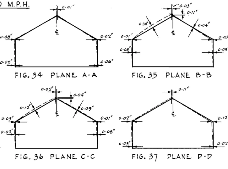
and 10 which were located at the junccdon of the exterior wall and the solid plaster partitions than it セ。ウ in tell-tales Nos. 5 and 6, at the same loads. The extent of cracking in tell-tales No.9 and No. 10 Clan be seen by comparing Figs. 108 and 109 with Figs. 110 and 11.1 which show the tell-tales before and after this loading condition was applied. The greatest lateral movement registered under this wind loading condition occurred at the end wall (Fig. 37, Sect. D-D) and reached a maximum value inward of 0.12 inch. The largest deflection in the rafters occurred at the third point of the house (Flgo 31, Sect. B-B) and reached a maximum valueoutward of 0.31 inch at the mid-span.
Dur-Lng the application of the more severe condit ions of loading, when loads simulating wind velocities of 70 to 90 mvp rh , with an internal pressure wer-e applied, a small crack which occurred earlier in tell-tale No.
6
extended across the ceiling side, as shown in Fig. 113. Thisextension took place at loads simulating a wind velocity of 80 m.p.h., and for comparison purposes, the uncracked tell-tale is shown in Fig. 112.
When this loading condition for internal pressure was repeated for wind velocities up to 120 m.p.h. very little
further damage took place, except for a small hairline crack in tell-tale No.2 and an extension of a previous crack in tell-tale No.5. The greatest deflection in the rafters occurred at the same point as it did during the application of loads for an internal suction condition. Under loads
simulating a wind velocity of 120 m.p.h. the rafters deflected outward to a maximum of 0.80 inch at the mid-span (Fig. 59, Plane
B-B).
Under the same loading, the greatest lateral movement in the exterior walls took place at the same cross-section.Under the combined loading of wind and snow there was no further significant damage caused to the test house. This condition of loading entailed a reversal of the direction of loading on the roof because of the greater magnitude of the downward thrust of the snow loading. It may be seen by a review of Figs. 62 and 85 that, as the wind loading was increased, the rafter deflections decreased because of the uplifting effect of the wind on the roof, hence the largest deflections in the roof under the combined loading were inward and occurred at the lowest value of wind velocity.
As the snow loading increments were applied in the final phase of the loading test, the deformations in the test house became more and more pronounced, (Figs. 88 to 107)
until failures began to occur in some parts of the roof
ウエセオ」エオイ・ 。セ 143 per cent of the design snow loading. At
100 per cent of design snow loading the largest deflections in the rafters reached values of 1.72 inches inward on the front slope and 0.55 inch inward on the rear slope. The allowable deflection (N.B.C., 1953) for a rafter having a horizontally projected span of 12 feet 2 inches, is 1/240 of the horizontal projection of the rafter or 0.61 inch, neglecting the support offered by the buckled collar ties. Therefore, in this test, the allowable deflection was exceeded on the front slopes by 182 per cent at design snow loading for this particular roof slope. When failures occurred.in the end collar ties and one rafter at 143 per cent of design snow loading, the rafter deflections had reached values of 3.87 inches on the front slope and 1.07 inch on the rear slope (Fig. 106, Sect. C-C) and there was a total of 1.96 inches of deflection in the ridge board towards the front slope on this plane of deflections.
The longitudinal 1- by 4-inch member which was fastened to the underside of the collar ties, and at
approximately their mid-point, was neither attached to the
gable ends nor, because of the central location of the chimney, continuous over the full length of the house. Consequently,
as the more severe conditions of snow loading were applied, the collar ties were free to buckle as two units in each end of the house on opposite sides of the chimney, thus affording little support to the rafters after initial buckling had
taken place. The action of the force set up by the opposing forces causing buckling in the collar ties can be seen in Fig. 86 which shows the failure of the splice in the
longitudinal 1- by 4-inch member, and the extent of lateral buckling. Figure 114 also shows similar buckling and the point of discontinuity in the longitudinal member near the chimney.
As the snow loading was applied, progressive damage took place in the interior of the test house, particularly at the intersection of interior partitions and exterior walls. The apparent action of the framing of the test house was for the exterior walls to move outward at eave level in most cases. This pattern of deformation was produced largely by the
spreading effect of the deflecting rafters and by ゥョ・ヲヲ・」エゥカセ
resistance of the ceiling joist to prevent this movement. At 75 per cent of design snow loading the exterior wall and the solid plaster partition separated at ceiling level at
tell-tale No.
9
to approximately the extent shown in Fig. 115. Under further loading this separation grew larger and asimilar separation took place on the opposite side of the room at tell-tale No. 10. This type of separation was due largely to the absence of studding in the partition and a double 2- by 2-inch wall plate which, in frame construction, is securely fastened to the exterior wall at the ceiling level. Although there was extensive cracking in the plaster tell-tales at other points in the test houseJ there were no
signs of apparent separation at the Junctions of the con-ventional partition walls and exterior walls, as shown in Figs. 116 and 117. Further evidence of the spreading of the exterior walls is shown in Fig. 118 where the front wall moved outward between the conventional partition walls of the
entrance and produced a fracture in the gypsum board ceiling.
7.
CONCLUSIONIt is difficult to compare the strength and rigidity of house frames because of their complexity of form, varia-tions in materials, workmanship, method of construction and may other factors which made a direct comparison obscure.
It is also realized that, before sUlficient information can
セセN gathered to establish criteria for assessing the relative strength of house frames, a number of structural tests are necessary. The investigation carried out on this experimental
house has been the first step by the Division in obtaining this requisite information and the results may be summarized as follows:
7.1 Roof
Excessive deflections occurred in the roof structure at design snow loading ゥョ、ゥ」。エセョァ (a) that the 2- by 4-inch rafters (which do not meet the requirements of the National Building Code,
1953,
or the present Central Mortgage and Housing Corporation Building Standards) on l6-inch centres were structurally inadequate; (b) that the 1- by 5-inch collar ties were sUbjected to compressive lQads and were not capable of resisting the induced compressive rorces effectively after initial buckling had taken place; (c) that the 1- by 4-inch longitudinal member attached to the underside of the collar ties was of little value in preventing the collar ties from buckling, because it was not continuous nor adequatelyattached to the gable ends. 7.2 Exterior Walls
Separations began to occur at the junction of the
.I.'ear exterior wall and the solid plaster partition walls under 75 per cent of design snow loading, indicating (a) that the load on the rafters tended to deflect the exterior side walls outward at the ceiling level at points where insufficient
resistance was afforded by the ceiling joists and the irterior cross-partitions; and (b) that the connections between the rear exterior wall and the interior solid plaster partitions was structurally inadequate in preventing this separation.
7.3 Racking Strength
Cracking of plaster tell-tales in the four corners of the test house was confined to tell-tale No.5, indicating
(a) that movements in the end walls which are confirmed by measured deflections, were small under racking loads; (b) that the let-in 1- by 4-inch corner bracing セイッカゥ、・、 sufficient resistance to the racking loads; and (c) that exterior
sheathing was not required for additional racking strength in the experimental house.
This report has been prepared to record the results of the Division's first full-scale loading test on a house. Much has been learned from this test which points the way to improvements in house design and improvements in testing
technique, whhiJ are now the subje ct of further studies.
8. ACKNOWLEDGMENTS
The author wishes to thank all those whose time and efforts contributed to the successful completion of this
project. Special acknowledgment is given to Mr. J.C. Elliott and assistants of Plant Engineering Services who helped with the preparations and dismantling of the testing equipment; Mr. F.R. Thurston and assistants in the Structures Laboratory
of the Division of Mechanical Engineering who gave freely of their time and equipment; Mr. J.D. DeBlois and assistants in the Photographic Section of the Division of Mechanical
Engineering who made photographic records during this investigation; and Mr. C. Moser and Mr. R.C. Latta of the Division of Physics who were present during the final stages of the test to measure deformations in the test house by a photogrammetric method.
The author also wishes to record his thanks to
Mr. W.R. Schriever who supervised testing during the author's absence and all present and former colleagues in the Building Design Section who assisted in this work.
To Mr. R.F. Legget, Director of the Division of
Building Research, acknowledgement is gratefully made for his encouragement and sustained interest in this project.
Reprinted April 1954. 88pp.
Housing and Home Finance Agency. Performance Standards (Structural and Insulation Requirements for Houses). Housing and Home Finance Agency Technical Ofrice. Washington 25, D.C. June 1947.
Isaacs, David J. The Structural Sufficiency of Domestic
Buildings. Department of Works an( Housing, Commonwealth Experimental BuiJrl1ng Station. Bulletin No.1. North Ryde, Sydney, nNセNwN June 1946.
Laurie, J.A.P. and Chas. A. Rigby. Some Further Investigations into the Structural'Requirements of Single Storey Urban Bantu Houses. South African Council for Scientific and Industrial Research. Bulletin No. 12. Pretoria, South Africa. June 1954.
55
pp.Ministry of Works. Studies No.1. London 1944.
House Construction. Post-War Building His Majesty's Stationery Office.
Ministry of Works. House Construction. Post-War Building Studies No. 23. His Majesty's Stationery Office. London 1946.
Nathan, N.D. Structural Requirements of Single-Storey Native Houses. South African Council for Scientific and
Industrial Research. Bulletin No.9, South Africa. December 1952.
National Research Council, Canada. National BUilding Code of Canada, 1953. Ottawa, 1953.
Short, A. and L.G. Simms. Survey of Loading Tests on Some Post-War Prototype Houses. The Structural Engineer. , p. 67-98. February 1949.
Thomas, F.G. Structural Engineering Research at the Building Research Station. The Structural Engineer. Vol. XXVI, No.2, 1948.
inomas, F.G. structural Requirements for Houses. Department of Scientific and Industrial Research. National
Building Studies. Special Report, No.1, 1948.
ャLセN Naval Civil Engineering Research and Evaluation Laboratory. Evaluation of a 4o-ft. by 100-ft. Arch Rib Prefabricated Metal Utility Building. Final Technical Memorandum M-039.
Port Hueneme, California. May 1, 1952.
U.S. Naval Civil Engineering Research and Evaluation Laboratory. Evaluation of a 40-ft. by 100-ft. Frameless Straight
Sided Prefabricated Metal Utility BUilding. Final 'I'ecrud ca l Memorandum M-,050. Port Hueneme, California. April 1, 1952.
オNセN Naval Civil Engineering Research and Evaluation Laboratory. Evaluation of a 20-ft. by 48-ft. Arch Rib Prefabricated Metal Barracks Building. Final Technical Memorandum M-055.
Port Hueneme, California. April 1, 1952.
Whittemore, H.L., and Ambrose H. Stang. Methods of
Determining the Structural Properties of Low Cost House Construction. National Bureau of Standards. Building Materials and Structures Report No.2. August 10, 1938. Yeates, C.S. The Application of Testing Methods to Modern
buゥャ、ゥョセ Techniques. Engineering Inspection. Vol. 12, No.4, p. 4-25. Winter, 1948.
-d-L.S. - Leeward Slope @...
+-CD
L.W. - Leeward Wall - Pressure Channel
Net
Surface Ib/sq.ft. Load Loading Load per Tare Net Pressure Head Pressure Pressure
(lb) Points Point Weight Load (p.s.i. ) (p.s.1. ) (p.e.i.) Channel
70 W.W. +5.5 +1665.9 4 +416.4 0 +416.4 310 1.7 311.7 1 " W.S. -0.2 -117.9 8 -14.7 +310.3 -325.0 100 3.8 103.8 2 " L.S. -2.7 +1591.1 8 -198.8 +310.3 -509.1 110 3.8 113.8 3 " L.W. -2.1 -636.1 4 -159.0 0 -159.0 110 1.7 111.7 4 80 W.W. +7.1 +2150.5 4 +537.6 0 +537.6 400 1.7 401.7 1 " W.S. -0.3 -176.8 8 -22.1 +310.3 -332.4 101 3.8 104.8 2 " L.S. -3.5 -2062.5 8 -257.8 +310.3 -568.1 114 3.8 117.8 3 " L.W. -2.7 -817 .8 4 -204.4 0 -204.4 145 1.7 146.7 4 90 W.W. +9.0 +2726.1 4 +681.5 0 +681.5 510 1.7 511.7 1 " W.S. -0.4 -235.7 8 -29.5 +310.3 -339.8 102 3.8 105.8 2 " L.S. -4.4 -2592.9 8 -324.1 +310.3 -634.4 121 3.8 124.8 3 " L.W. -3.4 -1029.8 4 -257.4 0 -257.4 185 1.7 186.7 4 100 W.W. +11.2 +3392.5 4 +848.1 0 +848.1 640 1.7 641.7 1 " W.S. -0.4 -235.7 8 -29.5 +310.3 -339.8 102 3.8 105.8 2 " L.S. -5.4 -3182.2 8 -397.7 +310.3 -708.0 140 3.8 143.8 3 " L.W. -4.2 -1272.2 4 -318.0 0 -318.0 230 1.7 231.7 4 110 W.W. +13.5 +4089.2 4 +1022.3 0 +1022.3 780 1.7 781.7 1 " W.S. -0.6 -353.6 8 -44.2 +310.3 -354.5 103 3.8 106.8 2 " L.S. -6.6 -3889.3 8 -486.2 +310.3 -796.5 160 3.8 163.8 3 " L.W. -5.1 -1544.8 4 -386.2 e -386.2 285 1.7 286.7 4 120 W.W. +16.1 +4876.7 4 +1219.1 0 +1219.1 940 1.7 941.7 1 " W.S. -0.7 -412.5 8 -51.5 +310.3 -361.8 105 3.8 108.8 2 " L.S. -7.8 -4596.5 8 -574.5 +310.3 -884.8 180 3.8 183.8 3 " L.W. -6.1 -1847.7 4 -461.9 0 -461.9 340 1.7 341. 7 4 pep. REpOP,T G'Z
0
L.S. - Leeward SlopeL.W. - Leeward Wall
.
....
- Pressure Channel
Wind Hydraulic Pressure Net
Ve1ocit
1
Surface 1b/sq.ft. Load Loading Load per Tare Net Pressure Head Pressure Pressure(m.p.h. (lb) Points Point Weight Load (p.s.i.) (p.s.i.) (p.s.i.) Channel
70 W.W. +2.1 +636.1 4 +159.0 0 +159.0 110 1.7 111.7 1 " W.S. -3.6 -2121.4 8 -265.2 +310.3 -575.5 170 3.8 173.8 2 " L.S. -6.1 -3594.7 8 -449.6 +310.3 -759.9 150 3.8 153.8 3 n L.W. -5.5 -1665.9 4 -416.4 0 -416.4 310 1.7 311. 7 4 80 W.W. +2.7 +817.8 4 +204.4 0 +204.4 145 1.7 146.7 1 " W.S. -4.7 -2769.7 8 -346.2 +310.3 -656.5 195 3.8 198.8 2 " L.S. -7.9 -4655.4 8 -581.9 +310.3 -892.2 180 3.8 183.8 3 " L.W. -7.1 -2150.5 4 -537.6 0 -537.6 400 1.7 401.7 4 90 W.W. +3.4 +1029.8 4 +257.4 0 +257.4 185 1.7 186.7 1 " W.S. -6.0 -3535.8 8 -441.9 +310.3 -752.2 220 3.8 223.8 2 " L.S. -10.0 -5893.0 8 -736.6 +310.3 -1046.9 215 3.8 218.8 3 " L.W. -9.0 -2726.1 4 -681.5 0 -681.5 510 1.7 511.7 4 100 W.W. +4.2 +1272.2 4 +318.0 0 +318.0 230 1.7 231.7 1 " W.S. -7.4 -4360.8 8 -545.1 +310.3 -855.4 260 3.8 263.8 2 " L.S. -12.4 -7307.3 8 -913.4 +310.3 -1223.7 245 3.8 248.8 3 " L.W. -11.2 -3392.5 4 -848.1 0 -848.1 640 1.7 641.7 4 110 W.W. +5.1 +1544.8 4 +368.2 0 +386.2 285 1.7 286.7 1 " W.S. -9.0 -5303.7 8 -662.9 +310.3 -973.2 290 3.8 293.8 2 " L.S. -15.0 -8839.5 8 -1l04.9 +310.3 -'1415.2 290 3.8 293.8 3 " L.W. -13.5 -4089.2 4 -1022.3 0 -1022.3 780 1.7 781.7 4 120 W.W. +6.1 +1847.7 4 +461.9 0 +461.9 340 1.7 341.7 1 n W.S. -10.7 -6305.5 8 -788.2 +310.3 -1098.5 325 3.8 328.8 2 " L.S. -17.8 -10489.5 8 -1311. 2 +310.3 -1621.5 335 3.8 338.8 3 " L.W. -16.1 -4876.7 4 -1210.1 0 -1219.1 940 1.7 941.7 4 V'AA^iGセ セ E.poセt (;,'2
W.W. - Windward Wall
L:J
セwQョ、
W.S. - Windward Slope Wnm
LOADS +t
DES IGN SNOW LOAD @).. _ ....L.S. - Leeward Slope INTERNAL SUCT ION 4 .. ...
CD
L.W. - Leeward Wall - Pressure Channel
Wind Wind
t
Snow Load Net Hydraulic Pressure Net PressureVelocity Surface Net Load per Point Load Pressure Head Pressure Channel
(m.p.h. ) (p.6.1. ) (p.B.1. ) (p. s.1. ) 70 W.W. +416.4 0 +416.4 310 1.7 311. 7 1 " W.S. -325.0 +1463.0 +1138.0 340 3.8 343.8 2 " L.S. -509.1 +1463.0 +953.9 196 3.8 199.8 3 " L.W. -159.0 0 -159.0 110 1.7 111. 7 4 80 W.W. +537.6 0 +537.6 400 1.7 401.7 1 " W.S. -332.4 +1463.0 +1130.6 338 3.8 341.8 2 " L.S. -568.1 +1463.0 +894.9 180 3.8 183.8 3 " L.W. -204.4 0 -204.4 145 1.7 146.7 4 90 W.W. +681.5 0 +681.5 510 1.7 511. 7 1 " W.S. -339.8 +1463.0 +1123.2 335 3.8 338.5 2 " L.S. -634.4 +1463.0 +828.6 165 3.8 168.8 3 " L.W. -257.4 0 -257.4 185 1.7 186.7 4 100 W.W. +848.1 0 +848.1 640 1.7 641.7 1 " W.S. -339.8 +1463.0 +1123.2 335 3.8 338.5 2 " L.S. -708.0 +1463.0 +755.0 150 3.8 158.8 3 " L.W. -318.0 0 -318.0 230 1.7 231. 7 4 110 W.W. +1022.3 0 +1022.3 780 1.7 781.7 1 " W.S. -354.5 +1463.0 +1108.5 330 3.8 333.8 2 " L.S. -796.5 +1463.0 +666.5 140 3.8 143.8 3 " L.W. -386.2 0 -386.2 285 1.7 286.7 4 120 W.W. +1219.1 0 +1219.1 940 1.7 941.7 1 " W.S. -361.8 +1463.0 +1101.2 329 3.8 332.8 2 " L.S. -884.8 +1463.0 +578.2 131 3.8 134.8 3 " L.W. -461.9 0 -461.9 340 1.7 341.8 4 D 6 R.. l<E-pO R..T G'2
- Pressure Channel OTTAWA AREA rRONT
d
REARHydraulic Pressure Net
Percentage Surface Ib/sq.ft. Load Loading Pt. LoadL Tare Net Pressure Head Pressure Pressure Design Load (lb) Points to Surface Weight Load (p.s.i.) (p.s.i. ) (p.s.i.) Channel
50 Rear +25.4 +13096.2 8 +1463.0 +310.3 +1152.7 345 3.8 348.8 2 " Front +25.4 +13096.2 8 +1463.0 +310.3 +1152.7 240 3.8 243.8 3 75 Rear +38.1 +19644.9 8 +2194.5 +310.3 +1884.2 525 3.8 528.8 2 " Front +38.1 +19644.9 8 +2194.5 +310.3 +1884.2 381 3.8 384.8 3 100 Rear +50.8 +26193.5 8 +2926.0 +310.3 +2615.7 782 3.8 785.8 2 " Front +50.8 +26193.5 8 +2926.0 +310.3 +2615.7 548 3.8 551.8 3 125 Rear +63.5 +32740.6 8 +3660.0 +310.3 +3349.7 1005 3.8 1008.8 2 " Front +63.5 +32740.6 8 +3660.0 +310.3 +3349.7 710 3.8 713.8 3 150 Rear +76.2 +39288.7 8 +4392.0 +310.3 +4081.7 1215 3.8 1218.8 2 " Front +76.2 +39288.7 8 +4392.0 +310.3 +4081.7 865 3.8 868.8 3 175 Rear +88.9 +45836.8 8 +5122.0 +310.3 +4811.7 1425 3.8 1428.8 2 " Front +88.9 +45836.8 8 +5122.0 +310.3 +4811.7 1020 3.8 1023.8 3 200 Rear +101.6 +52384.9 8 +5852.0 +310.3 +5541.7 1650 3.8 1658.8 2 " Front +101.6 +52384.9 8 +5852.0 +310.3 +5541.7 1175 3.8 1178.8 3 225 Rear +114.3 +58933.0 8 +6543.0 +310.3 +6232.7 1850 3.8 1858.8 2 " Front +114.3 +58933.0 8 +6543.0 +310.3 +6232.7 1320 3.8 1323.8 3 I I
= <o::t-I .q-c BEDROOM セ 2 ・LeNNoセoom
1t3
UTILITY TRAP Door;r---y
II
II
I I I L __---l セ l- I-
r--r
I
r
FUP,NACE.•
.L---
-セ
""I•
セII
TIl
0
l:JATH r -.::::::::; e - - - LtVI ヲLedセoom"1
(
]
r-....5 4..1セ
r--...2 r-KtTCHE.N D!NING 13 NGL
E. (:,E...N D: c:::::::J \vOOD pAp.r /TION - '2tI PLAS TE..R PARTInON (SOLID)セ plaUteNセ TE.LL-TALE.S
FIGURE. J FLOOR PLAN OF
E.XPE..RIME-NTAL
HOUSE. N° 2I " , " SCALE.: Y4"'/-0
ALL STUDS 2Kx41 'fi) 1G1" O.C-. • • II 2 x8 JOISTS tW 1£0 O.G セ <f) - I co
B
i I " ,I Ix4 R UNNE..fl, II • II 2 "<D JOISTS Q iセ O.C...
セセ....
"W/h:--WA.i 。ャセャ. セOOL セi|G I n I II SCALE.: 14=1-0 :.
pLocセFIG U
P.
f.'2
CROSS SE.CT ION OF E.XPE..RIME..NTAL HOUSE.N° 2
.3"
aoc«
,VOOL INSUL.t
VAPOUR, BARR1E.p, PApEP. /I-%
GYPSUM BOARD 1" INSULATION BATT'S -r": 4# /::J ,1 J:. セ セ iセ c.c. : \ 12# SATURATED FELT ALUMINUM ALUMINUM SIOING 12.r' 5ATUR.AT£D FELTSCAL..E-\'1'; ... ' -
0"Fig. 6 First Bailey Bridge A-Frame Being Erected
tV1-1IFFLE.--TRE..£, !VALL 8£ARING
PAD
LLセN・ 1Z1!.?O/2.r {"'2
J..IYD!?ALlLIC RAM ANO TEN:iION AND COMPP,£SS/ON 5TRUT
of
LOADING
NOTE..:
t)
IG TRIBUTARY AP,EAS lVITH 4 POINT LOADING-f
RAFT£RS ON セoof2)
8 TP.IBUTAR,Y AR,£AS \VITI-/2
POINT LOAOING
Df
STUDDINGON 51D£ \VALLS.
POINTS
IV!-IIFFL£1R,£L
ROOF 8EARING PAD ... 24'- 4-'1 L.a,e:,E-,N D :
+
INWARD Tf-IP,UST¢
OUTWARD Tf-IRUSTfiH[uセl
8
·
ll::·
I:Q·
A\V :
Y'2
\V !7 D B/fOTJ./of
HOLlS£-,Y'2
\Vc.
c
B BFRONT
E..LE..VATION A A \V :: lVlOTI-I 0 HOL/!>E.. PLANE...SA'
II LE.Ga..ND:0+ /-lOR / ZONTA L DE..-FLE..-CTION IV /
RE..-セ HORIZONTAL AND veNMヲILイOcaセ O£FL£C.T/ON IV/A£""
PLANE...S B
4
c
NOTE.-:
arセoivU POINT A\VAY FRoM R£F£RENC&
pOINT IN OIRE-CTION ,,/ DEFL.E.CT/ON IVIR.£
FIGURE.... 10
P LA N E..-S
Fig. 12 Deflection Board and Recording Chart
ANO OE..fLE..CTION pOINTS
INTE...RNAl. sueTION
LE.GE..Nt7:
¢
\I/INO OIQ.E.,CTION NOT t..: tJ£FO/?MAT/ONS ARE- NOT TO 5CALE., " CENTRE.. " LINE-" セヲ UNOI5TORTE..D FRAME-l?ISTORTE-17 FRAME..\VIND
VELOCITY
70
mileNセPE.R
セour---00 0 . 3"
00 0 ' 2 '
FIG.. I
4-
P LAN L A-AFIGo
15
PLANE....- B-B" セ⦅ッ⦅ッ 0'2 0---=·ッセイッNMM I " 0·0'2 " 0-02
0_01" O.OtII 0-0'2"
MセM セセM
0-0,3
FIG .. 18
PLANE.. A-A
FIG.
19
PLANL B-I>
PLANl D-D
FIG. 21
PLANE..
c-c
0-07" ---it+--" 0-0'2FIG. 10
\VIND VE.LOC ITY
C}O
mMpNセNo·oi'
FIG" 22
PLANE...
A-A
FIC,.73
PLANE... &-B
II II
o-0'2 0-0'2
"
0·05
0·03
"
0·04 a.oz'
-
...+-=--FIGo
RセPLANE.-
A-A
FIGo
27
PLANE.. B - 8
II II 0·03 -0·0'2 0'02" ___-'t4--o- os' " 0-0'2
-If セ]]]ャ]BPGQOFIGo
2;
PLANL
D-{7
/I 0-0.5"
0'0'2 0.0'1" " a-o-z II 0-05 FIG.28PLANE...
c -
C
\V
\1\1
D VE.l 0CIT
Y
110M. P. H.
"
0·08
--=---...-FIG ..
';4-
PLANE..- A-AO.O'z" o-os" MMMエBGセ FIGo