Publisher’s version / Version de l'éditeur:
Vous avez des questions? Nous pouvons vous aider. Pour communiquer directement avec un auteur, consultez la première page de la revue dans laquelle son article a été publié afin de trouver ses coordonnées. Si vous n’arrivez pas à les repérer, communiquez avec nous à PublicationsArchive-ArchivesPublications@nrc-cnrc.gc.ca.
Questions? Contact the NRC Publications Archive team at
PublicationsArchive-ArchivesPublications@nrc-cnrc.gc.ca. If you wish to email the authors directly, please see the first page of the publication for their contact information.
https://publications-cnrc.canada.ca/fra/droits
L’accès à ce site Web et l’utilisation de son contenu sont assujettis aux conditions présentées dans le site LISEZ CES CONDITIONS ATTENTIVEMENT AVANT D’UTILISER CE SITE WEB.
Paper (National Research Council of Canada. Division of Building Research),
1979
READ THESE TERMS AND CONDITIONS CAREFULLY BEFORE USING THIS WEBSITE.
https://nrc-publications.canada.ca/eng/copyright
NRC Publications Archive Record / Notice des Archives des publications du CNRC :
https://nrc-publications.canada.ca/eng/view/object/?id=9f687213-1a61-4ad0-ab43-709bbb4a9720 https://publications-cnrc.canada.ca/fra/voir/objet/?id=9f687213-1a61-4ad0-ab43-709bbb4a9720
NRC Publications Archive
Archives des publications du CNRC
This publication could be one of several versions: author’s original, accepted manuscript or the publisher’s version. / La version de cette publication peut être l’une des suivantes : la version prépublication de l’auteur, la version acceptée du manuscrit ou la version de l’éditeur.
For the publisher’s version, please access the DOI link below./ Pour consulter la version de l’éditeur, utilisez le lien DOI ci-dessous.
https://doi.org/10.4224/40001222
Access and use of this website and the material on it are subject to the Terms and Conditions set forth at
Long-term performance of a machine-bored tunnel with use of an
unreinforced, precast, segmented concrete lining in soft clay
N21d
National Research
'Conseil national
0.864
I
$
Council Canada
de recherches Canada
LONGcTERM PERFORMANCE OF A MACHINEBORED
TUNNEL WITH USE OF A N UNREINFORCED, PRECAST,
SEGMENTED CONCRETE LINING I N SOFT CLAY
by J.H.L. Palmer
andD.J. Belshaw
Preptint for
TUNNELLING
'79The second international symposium, organized by the Institution
of Mining and Metallurgy
held in London, England, 12
-
16 March
19796 P*
DBR Paper No. 864
Division of Building Research
SOMMAIRE
Un tunnel a dt6 construit
I
Thunder Bay, au Canada,I
l'aide d'une machine foreuse et d'un revstement en bdton prBfabriqu6, segment6 et non boulonn6. Le revstement comporte des anneaux de 2.16 m de diamstre compos6s de quatre sections trap6zoPdales en beton non arm6 (1 rn delongueur et 11 cm d'dpaisseur). Chaque anneau a 6t6 assemble 3 l'abri du bouclier arribre de la machine foreuse. Les nombrew appareils qui ont fourni des donndes tout au long des travaux ont Btd protdgds aprSs la construction pour permettre une auscultation 5 long terme. On pr6voit continuer les observations pendant au moins cinq ans. Le present expos& decrit le projet et le rendement du systsme utilisd
pour les travaux, puis prssente des donnges pour les deux premieres ann6es d'observation qui ont suivi la mise en place des instruments. Au cours de cette pCriode, une surcharge d'environ 1 m de terre a kt6
ajoutCe sur une partie du tunnel oG se situait une des deux batteries d'instruments.
litted for um-to b 7 - discussic le held in I-*- - _ _ I. ~n at the London .-..-At-- This paper will be subrr
Tunnelling '79 symposi~
from 12 to 16 March, 1913. rreprlms are lssuea Tor
the use of symposium registrants. All papers presented at the symposium will be published, with discussion, authors' replies and name and subject indexes, in a volume of proceedings-
Tunnelling '79--obtainable in late 1979-early 1980 from the lnstitution of Mining and Metal- lurgy, 44 Portland Place, London W I N 4BR, England.
The second international symposium, organized by the Institution of Mining and Metallurgy, with the cooperation of the British Tunnelling Society, the lnstitution of Mining Engineers and the Transport and Road Research Laboratory
LONDON 12-16 MARCH 1979
Paper
19
Long-term performance of a
machine-bored tunnel with use
of an unreinforced, precast,
segmented concrete lining in
soft clay
J.
H.
L. Palmer
D.
J. Belshaw
Irma
ot a macn~ne-oored
tunnel with use of a
unreinforced, precasr,
segmented concrete
lining in soft clay
J. H. L. Palmer M.A.Sc., Ph.D., P.Eng.
Geotechnical Section, Division of Building Research National Research Council of Canada, Ottawa, Ontario, Canada
D.J. BelshawM.Sc.,M.I.C.E.,M.A.S.C.E.,P.Eng.
Morton & Partners, Ltd., Rexdale, Ontario, Canada
Synopsis
A tunnel has been constructed in Thunder Bay, Canada, by use of a tunnel boring machine and an unbolted, precast, segmented concrete lining. The lining consists of 2.16-m diameter rings composed of four trapezoidal sections of unreinforced concrete 1 m in length and 11 cm thick. Each ring was assembled within the protection of the tailpiece of the tunnel boring machine. Extensive field instrumentation that provided data on performance during construction was protected after construction so that long-term monitoring could be undertaken. I t is expected that observations will be continued for at least five years.
The project and the performance of the tunnelling system during construction are reviewed, and data from the first two yean of observations following the installation of the instruments are presented. During this period a surcharge of about 1 m of soil was added over part of the tunnel alignment, including one of the two instrument arrays.
In March, 1976, construction was begun on a
3.3-km section of a 2.16-m diameter sanitary trunk
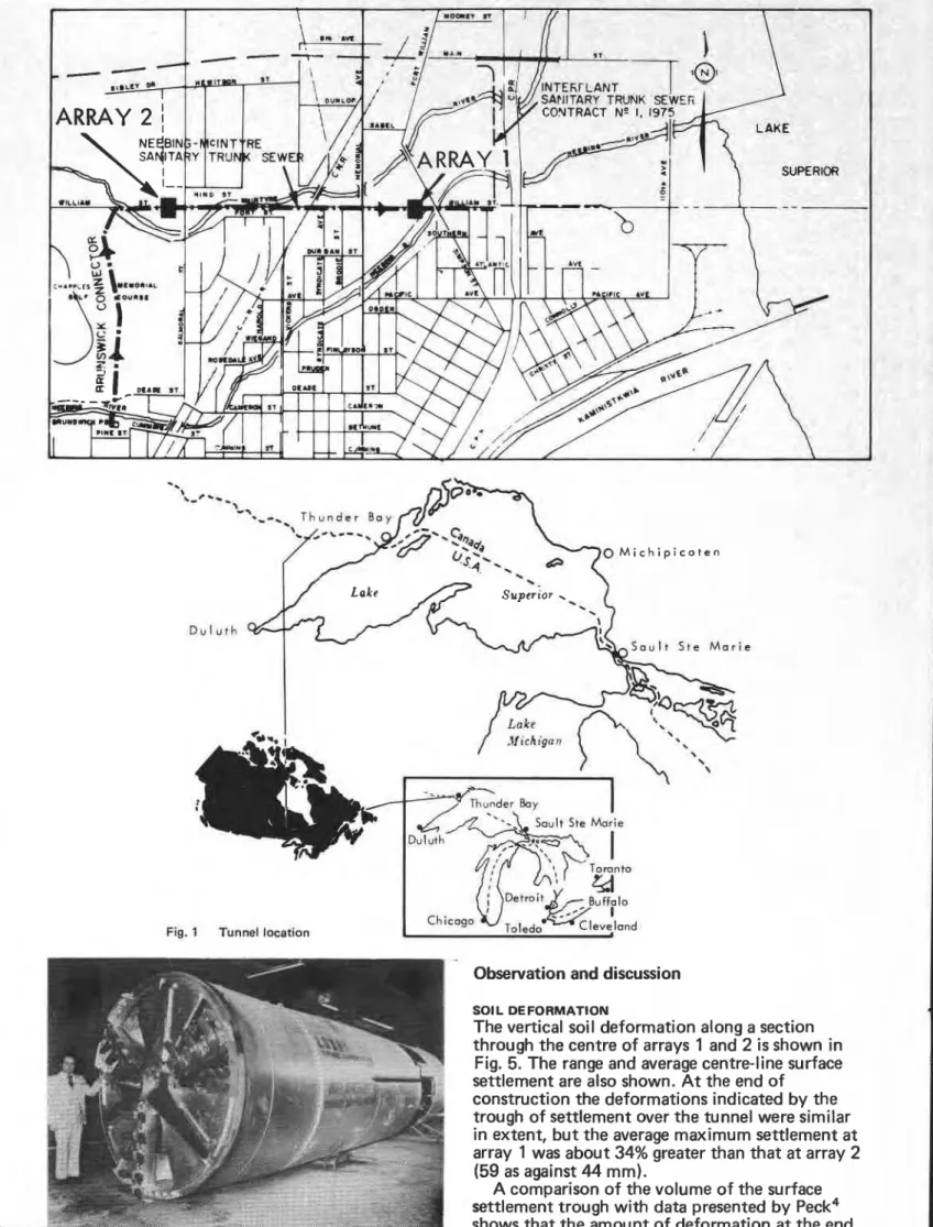
sewer in the city of Thunder Bay, Canada ( Fig. 1). Although the subsoil of soft to firm clay overlain by saturated loose sand was known to be difficult
for tunnelling, the contractor chose to use a
technique novel to North America, i.e. a tunnel
boring machine together with an unreinforced, unbolted, segmented precast tunnel lining. The tunnel was constructed within the clay deposit with a depth to invert of about 11-12 m.
An extensive field instrumentation programme was undertaken to document the performance of the tunnelling system and to permit long-term monitoring of the completed tunnel. Two arrays of instrumentation were planned for the project. The first, installed close to the start of construction, provided very satisfactory documentation of the initial overall performance of the tunnel.' Because of the success of the first array, the second array was redesigned to provide more detailed
information on the spatial distribution of
deformations and pore pressure, with less emphasis on overall behaviour. The data obtained during construction and for the following eleven months have been reported by Palmer and ~ e l s h a w . ~ Most of the instruments have been protected to permit long-term monitoring.
The current paper will summarize and compare the information previously published and present the first two years of observations. Approximately one year after construction a fill of about 1 m was
aced ove st array Ir a porti of instri .., e tunnel, on, and dori thls surcnarge WIII De IncluL,,.
,
includii the influ ng the ence ofThe achine Tunne~~lng
A detailed UCXXI~LIUII UI L I I ~ t u n n e ~ ~ r ~ ~ y tJ~-edure
has been given by Morton and
co- worker^.^
system employs a full-face tunnel boring m,
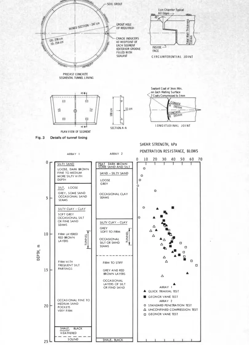
(Fig. 2) together with an unbolted, precast, segmented concrete tunnel lining. Each ring lining i s 1 m long and is composed of four trapezoidal-shaped segments of unreinforce
concrete 1 1 cm thick (Fig. 3). The mined d ~ a ~ IIGLGI
of the tunnel i s 2.47 m and the outside diameter of the completed lining is 2.38 m. The lining is
designed to serve as both the primary and secondary support. Because the soil i s not
self-supporting, the lining must be assembled within the protection of the tailpiece of the tunnelling machine, which then advances by thrusting on the completed lining. During the advance, clay grout is injected into the tailpiece void. A key element in the system is an erector arm specially designed to lift and erect the segments. One ring can be assembled in 5-10 min and progress rates of 29 m of completed tunnel per 8-h shift have been achieved.
Subsoil conditions
The tunnel is constructed within a deltaic plain formed a t the confluence of the Neebing, Mclntyre and Kaministikwia Rivers in the City of Thunder Bay, Ontario. The stratigraphy a t the site of each array is shown in Fig. 4. Some 6-7 m of postglacial fluvial s i l t and sand i s underlain by about 17-18 m of late glacial lacustrine deposits of layered and varved clays that extend to the black shale bedrock. The granular deposits are generally very loose to loose in relative density; the cohesive deposits are of soft to firm consistency and are lightly
overconsolidated. Instrumentation
I t is not within the scope of this paper to present the details of the instrumentation for the project
(see Belshaw and Palmer1 and Palmer and ~elshaw?. At each site observations were taken of vertical and lateral soil deformation, pore-water pressure and total pressure on the tunnel lining. Surface
settlement was monitored a t array 1 for 22 m on
either side of a 60-m length of tunnel, commencing
about 90 m from the first shaft. All other
instruments were concentrated near the centre of the array. A t array 2 surface settlement was
monitored over the centre line of the tunnel
-
alonga length of about 48 m and a t one cross-section only. All other instrumentation was concentrated as close as possible to the cross-section, with emphasis on pore pressure changes and spatial soil deformations in the vicinity of the tunnel.
Additional information obtained during the construction period included detailed observations of the tunnelling procedure through the array, closure of the lining, weight of spoil removed
(array 1) and stress in the tunnel lining. After the completion of the tunnel construction the principal instruments in array 3 and all instruments in array 2 were protected to permit long-term monitoring of the project
*. '. ,* -,, 0 M i c h i p i c o t e n D u l u t h S o u l t S t e M a r i e
Fig. 1 Tunnel location
Duluth
Chicago
Observation and discussion Sol L DEFORMATION
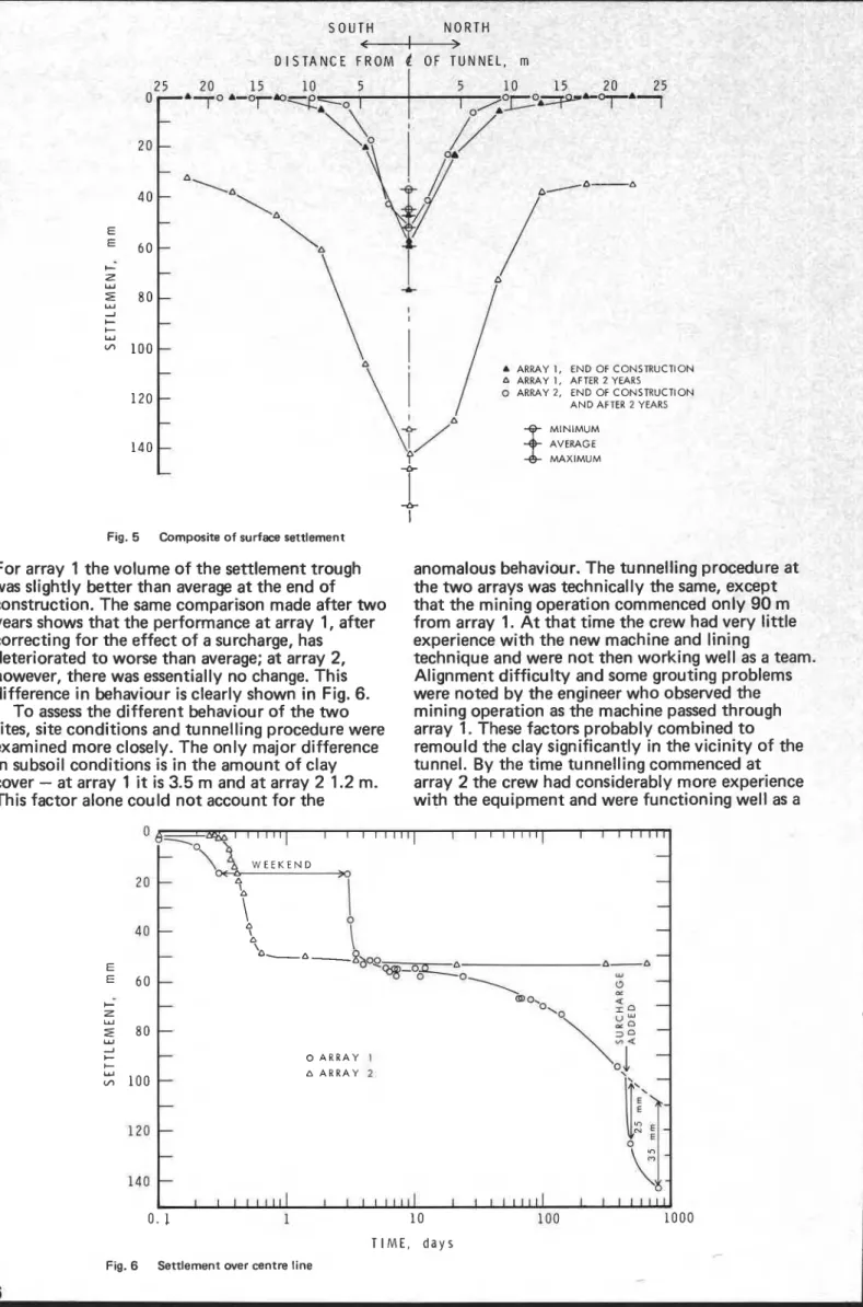
The vertical soil deformation along a section through the centre of arrays 1 and 2 i s shown in Fig. 5. The range and average centre-line surface settlement are also shown. At the end of
construction the deformations indicated by the trough of settlement over the tunnel were similar in extent, but the average maximum settlement a t array 1 was about 34% greater than that a t array 2 (59 as against 44 mm).
A comparison of the volume of the surface settlement trough with data presented by Peck4 shows that the amount of deformation a t the end
Fig. 2 M-97 Lovat tunnel machine. Reproduced by courtesy of of ~ 0 n ~ t r ~ ~ t i 0 n for array
2
is substantially betterCRACK INDUCERS ATMIDPOINT OF EACH SEGMENT (EXTERIOR GROOVE:
FILLED WITH FACE
CIRCUMFERENTIAL JOINT
PRECAST CONCRETE SEGMENTAL TUNNEL LINING
Sealant Coat of 3mm Min.
s [ # c m I
5
E u SECTION A-APLAN VIEW OF SEGMENT Fig. 3 Details of tunnel lining
ARRAY 1 ARRAY 2
SILTY SAND LOOSE, DARK BROWN FlNE TO MEDIUM MORE SILTY WITH DEPTH
SILT, LOOSE
-
GREY, SOME SAND OCCASIONAL SAND SEAMSSILTY CLAY - CLAY SOFT GREY OCCASIONAL SlLT OR FlNE SAND SEAMS FIRM LAYERED
1
RED BROWN LAYERS 2 FlRM WlTH FREQUENT SlLT PARTINGS OCCASIONAL FlNE TO MEDIUM SAND POCKETS VERY FlRM SHALE, BLACK-
WEATHERED- - -
SOUNDPEAT DARK BROWN SOME SAND A N D SILT
SAND - S I L N SAND LOOSE GREY OCCASIONAL CLAY SEAMS SILTY CLAY - C L A Y GREY S OTO FIRM
4[
OCCASIONAL SlLT OR SAND SEAMS---
FIRM TO STIFF GREY A N D RED BROWN LAYERS OCCASIONAL LAYERS OF SlLT OR FIND SAND SHALE. B U C K.on Each Matina Surface
LONGITUDINAL JOINT
SHEAR STRENGTH, kPa
PENETRATION RESISTANCE, BLOWS 0 10 20 30 40 5 0 6 0 70 0 A a A ARRAY 1
A QUICK TRlAXlAL TEST GEONOR VANE TEST
ARRAY 2
0 STANDARD PENETRATION TEST A UNCONFINED COMPRESSION TEST
0 GEONOR VANE TEST
I I I I I I .
SOUT 4 . - - NORTH
-
. - - . . .Fig. 5 Composite o f surface settlement For array 1 the volume of the settlement trough was slightly better than average a t the end of construction. The same comparison made after two years shows that the performance a t array 1, after correcting for the effect of a surcharge, has deteriorated to worse than average; a t array 2, however, there was essentially no change. This difference in behaviour is clearly shown in Fig. 6.
To assess the different behaviour of the two sites, site conditions and tunnelling procedure were examined more closely. The only major difference in subsoil conditions is in the amount of clay cover
-
a t array 1 it is 3.5 m and a t array 2 1.2 m. This factor alone could not account for theanomalous behaviour. The tunnelling procedure a t
the two arrays was technically the same, except
that the mining operation commenced only 90 m
from array 1. A t that time the crew had very little experience with the new machine and lining
technique and were not then working well as a team.
Alignment difficulty and some grouting problems were noted by the engineer who observed the mining operation as the machine passed through array 1. These factors probably combined to remould the clay significantly in the vicinity of the tunnel. By the time tunnelling commenced a t
array 2 the crew had considerably more experience
with the equipment and were functioning well as a
' - o < ~ ' i ~ ~ ~ \ ~ ~ > I
' " "
I I 1 1 I l l 1 1 I 1 1 1 1 1 1 1 --
-
-
-
't,
I
-
0-
n-
-
-nib\8,
n-
n-a 'Q8-OO--
"J-
4-
-
0 A R R A Y I n A R R A Y 2-
-
-
-
-
1 I 1 1 1 1 1 1 1 I I 1 1 1 1 1 1 1 I I l l 1 10 100 TIME, d a y sFig. 6 Settlement over centre line
team (2 shift mil
. - .
workma cover. 1 m of tl ning thrc..
-
nship ca eted in the 8-h le most significar ractors, tneretore, seem to be the quality ofwith the amount of clay
INFLUENCE OF SURFACE SURCHARGE
Array 1 is located in the centre of a large field
-
part of the Lakehead Exhibition Grounds. The area has been subjected t o minor flooding each spring and when fill from nearby road construction became available it was a logical, though
unexpected, disposal site. Approximately 1 m of fill, consisting of mixed granular materials and
slabs of asphalt and concrete, was placed over a
large area of the tunnel, including the instruments of array 1. When the filling was completed the instruments were extended to the new ground surface and reprotected.
The best indication of the overall influence of
the surcharge is the settlement of the two most
northerly points in Fig. 5
-
points that lie outsidethe influence of the tunnel. On the south side the depth of surcharge was about 0.6 m a t 20 m from the centre line and gradually petered out to the south. About 35 mm of settlement can be attributed to the surcharge load alone. Of that amount, 25 mm had already occurred within six
weeks of the filling operation. This behaviour is
consistent with the fact that consolidation tests for the upper 6 m of clay stratum indicate an
overconsolidation ratio of about 1.4, so the
surcharge load is within the preconsolidation range.
Data obtained from magnetic extensometers in the vicinity of the tunnel indicated that most of the settlement attributable to the surcharge load had occurred within the clay stratum. I f the settlement curve is corrected for the effect of surcharge
(Fig. 61, there is indication that reconsolidation of
the clay near the tunnel is approaching completion.
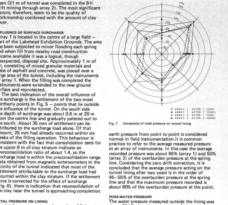
TOTAL PRESSURE ON LINING
The total pressure measured on a ring of lining a t each array is shown in Fig. 7. Ei3ht pressure cells were installed in each ring a t 45 intervals and duplicate cells were installed a t the crown, invert and spring lines. At each array 1 1 cells are still functioning after two years. The total pressure distribution on each ring is symmetrical, but not uniform. A t array 2 there is some evidence of redistribution of pressure in the second year and an overall slight decrease in pressure. A t array 1 the pressure has increased significantly in the same period, but this increase includes the effect of the surcharge load, which was about 20 kPa. A set of readings was not obtained just before the fill was
added, so it is not possible to differentiate
precisely between pressure increases due to
reconsolidation and those due to surcharge, but the effect of the surcharge appears to have been an approximately uniform increase in pressure. The maximum recorded pressure on each ring after two years was about 95% of the overburden pressure a t the measuring point. These readings have not been corrected for zero drift of the pressure transducers. The correction after two years has been difficult to establish, but it may be in the order of -7 to -1 4 kPa, so the recorded pressures represent the probable maximum a t each point.
Because a variation of *25% in the measured
0 A R R A Y I AFTER 1 Y E A R A R R A Y 1 AFTER 2 YEARS A A R R A Y 2 AFTER 1 YEAR A A R R A Y 2 AFTER 2 YEARS
Fig. 7 Composite of total pressure on tunnel lining
earth pressure from point to point is considered
normal in field instrumentation it is common
practice to refer to the average measured pressure a t an array of instruments. In this case the average recorded pressure was about 65% (array 1) and 50% (array 2) of the overburden pressure a t the spring
line. Considering the zero drift correction, it is
concluded that the average pressure acting on the
tunnel lining after two years is in the order of
45-55% of the overburden pressure a t the spring
line and that the maximum pressure recorded is
about 90% of the overburden pressure a t the point.
PORE-WATER PRESSURE
The water pressure measured outside the lining was about 60 kPa (maximum) a t array 2, but only about 15 kPa a t array 1 two years after
construction. This difference is mainly a result of early problems with the joint seals. As the work progressed, the sealant, which was an elastomeric compound, was modified and better seals were achieved.
A t the time of the two-year readings the site of array 2 was flooded and it was not possible to read most of the piezometers. Readings after one year indicated very little effect on water pressure except in the immediate vicinity of the tunnel, i.e. within 1 m. This minimal effect has been interpreted as an indication that the clay grout and the disturbed soil around the tunnel are acting effectively as a sealant for the tunnel.
TUNNEL PERFORMANCE
At both instrumented arrays visual inspection of the tunnel indicated that the segmented lining was performing satisfactorily, although the performance and sealing of the joints could be improved. A t the beginning of the project there was some difficulty with breakage of the segments, particularly during transport by truck 1440 km from the casting plant to the job site. Once essential routines were
established there were no handling problems either during shipping or during erection. The mechanical
erector arm performed very well and excavation and lining could be achieved as fast as, or often faster than, materials could be transported in or out of the tunnel. Observations of lining performance within the limits of each array indicated that cracking of the segments was occurring as planned along the line of the crack inducer. Less than 4% of the segments cracked otherwise.
Conclusions
Two years of observation of the performance of the tunnel after construction have led to the following conclusions.
(1) The tunnel is performing satisfactorily, confirming an earlier conclusion that the combination of a tunnel boring machine and a
precast, unreinforced, unbolted, segmented lining is
a successful tunnelling procedure in soft to firm clay.
(2)
The quality of workmanship, combined with the amount of clay cover, seems to have a dramatic effect on the amount of long-term settlement over the tunnel. Settlement over the section constructed during the 'shakedown' stage of the contract has been more than double that recorded for a later section of tunnel and i s continuing to increase slowly.(3) A 1-m fill over the tunnel caused an overall increase in settlement and a uniform increase in pressure on the tunnel lining, but it has had no adverse effects on the tunnel itself.
(4) The average total pressure acting on the lining is in the order of 45-55% of the overburden pressure. The maximum pressure recorded is about 90% of the overburden pressure.
Acknowledgment
The instrumentation programme was funded, in part, by the Corporation of the City of Thunder Bay through their Consulting Engineers for the project, R. V. Anderson Associates, Ltd., in part through a contract between the Department of Supply and
Services of Canada (DSS) and Morton & Partners, Ltd., and in part by the Division of Building Research of the National Research Council of Canada. Morton & Partners, Ltd., were contract managers for the project and the Division of Building Research was the scientific authority for the DSS contract. R. V. Anderson Associates, Ltd., supplied personnel for some of the field work and provided the necessary liaison for the project.
This project could not have been undertaken without the permission and cooperation of the Corporation of the City of Thunder Bay, the
General Consultant, R. V. Anderson Associates, Ltd., and the General Contractor, Mole Construction Co. of Cleveland, Ohio, and Thunder Bay. In addition, the cooperation of the tunnel boring machine manufacturer, Lovat Tunnel Equipment, Inc., of Toronto, Ontario, and the segment fabricators, Pre-Con, .Ltd., of Brampton, Ontario, is gratefully acknowledged.
This paper is published with the approval of the Director of the Division of Building Research, National Research Council of Canada, of
R. V. Anderson Associates, Ltd., Consultants to the Corporation of the City of Thunder Bay, and of Mole Construction Co., the General Contractor.
hrences Belshaw C A - - -A-A. 1. J. and Pal .-
.-..-
,..:--.
Results o ---*-A ) f a progran I -83. I. D. Use of clay. In Get . . a precast, o technical lmer J. H. Ilnsrrumenrarlon lnvolvlng a precast, seynrel8rar. ~;UIILI~;~C-IIIICU tunnel in clay. Can. sotech. J., 15,1978,573-
2. Morton J. D. Palmer J. H. L. and Dunbar 0
segmented, concrete lining for a tunnel in soft
aspects of soft clays: proceedings of the internaaona~ symposrum on soft clays, Bangkok, 1977 Brenner R. P. and Brand E. W. I
(Bangkok: Asian Institute of Technology, 19771,587-98
3. Palmer J. H. L. and Belshaw D. J. Deformations and p
pressures in the vicinity of a precast, segmented, concrete. tunnel in clay. Paper presented to 31st Canadian geotechn conference, Winnipeg, October 1978.
4. Peck R. B. Deep excavations and tunnelling in soft grc
Proceedings 7th international conference on soil mechanic* drru
foundation engineering, Mexico, 1969, state of the art volume
(Mexico City: Sociedad Mexicana de Mec6nic.a de Suelos, 19691, 225-90. eds ore .I Urn,."" innrl I ical und. In
__
__-I -- -8 - -- P r i n _ t g e @ a n d by Stt phen AustinIHertfordThis publication is being distributed by the Division of Building R e s e a r c h of the National R e s e a r c h Council of Canada. I t should not b e reproduced i n whole o r i n p a r t without p e r m i s s i o n of the original publieher. The Di- vision would b e glad t o b e of a s s i s t a n c e i n obtaining s u c h permission.
Publications of the Division m a y b e obtained by m a i l - ing the a p p r o p r i a t e r e m i t t a n c e (a Bank. E x p r e s s , o r P o s t Office Money O r d e r , o r a cheque, m a d e payable to the R e c e i v e r G e n e r a l of Canada, c r e d i t NRC) t o the National R e s e a r c h Council of Canada, Ottawa. K1A 0 R 6 . Stamps a r e not acceptable.
A l i s t of a l l publications of the Division i s available and m a y be obtained f r o m the Publications Section, Division of Building R e s e a r c h , National R e s e a r c h Council of Canada. Ottawa. KIA OR6.