3
Bimanual Cross-Coupling in Space Telerobotics
byVictor Wang
Submitted to the Department of Mechanical Engineering on January 26, 2012 in partial fulfillment of the requirements for the degree of
Master of Science in Mechanical Engineering
Abstract
Astronauts spend much time training to control the robotic arm aboard the International Space Station, and must perform a variety of challenging, three-dimensional tasks. They use a unique, bimanual control system to control the velocity of the end-effector; the left hand controls
translation in three axes while the right hand simultaneously controls rotation in three axes. Operator inputs to the bimanual controllers can cross-couple through not only intermanual neuromotor pathways, when movement of one hand affects movement of the other hand, but also through intramanual pathways, when movement of one hand affects movement of the same hand in an unintended control axis.
We developed a measurement technique to quantify these directional cross-coupling pathways based on the detection of frequency-coded command signals in a bimanual tracking task. The technique allowed us to characterize the interactions among all six control axes in the form of a cross-coupling matrix of coupling strengths. An experiment using these techniques suggested two principal pathways of intermanual coupling and one of intramanual coupling. By combining information across 18 human subjects to typify the cross-coupling response due to the bimanual control system, we found that the two intermanual pathways exhibited 21% yaw to lateral
translation and 15% pitch to vertical translation mean coupling even after significant training. The intramanual pathway exhibited 41% roll to yaw mean coupling.
We found significant differences in bimanual cross-coupling between subjects, and
demonstrated that subjects could significantly reduce intermanual cross-coupling with practice, suggesting that these metrics may be useful indicators of control device mastery. We found statistically significant negative correlations between early-stage intramanual coupling and subsequent performance in a simulated space telerobotics track and capture task, suggesting that an intramanual coupling metric may be useful as a predictor of human telerobotic
performance. The test technique could ultimately be applied to evaluate cross-coupling during astronaut training and also to reduce undesired cross-coupling through improved hand
controller design. Our results supported an ergonomic basis for intermanual cross-coupling that incorporated both biomechanical effects and sensorimotor effects.
Thesis Supervisor: Charles M. Oman
4
Acknowledgements
Thanks to Dr. Charles Oman for providing the direction and grounding wisdom for this project. Your mentorship and advice were indispensable.
Thanks to Dr. Alan Natapoff for sharing your experience in statistics, useful research insights (such as the conception of the multiplicative gap filter), interesting anecdotes, granola bars, enthusiasm and friendship.
Thanks to Dr. Andrew Liu for inviting me into the MVL, helping with many software and hardware aspects of the RWS simulator, and always being supportive.
Thanks for Dr. Neville Hogan for your ongoing educational and research support, both during the 2.151 recitations and also as my thesis reader.
Thanks to Dr. Dagmar Sternad for introducing us to your lab at Northeastern University and providing interesting research perspectives.
Thanks to Rachel Forman, Caroline Lowenthal, Raquel Galvan, Dominic Gallegos, Corine Sinnette, Erin Evans, Melanie Rueger, Dr. Steven Lockley and everybody else involved in the fatigue study who helped make those sleepless nights tolerable.
Thanks to Teresa Pontillo for providing information about your previous research, and giving me a head start on my own literature search.
Thanks to Liz Zotos for always being there and for making sure my subjects were happily paid. Thanks to all of my subjects for your patience and enthusiasm.
Thanks to all the other present and former MVL students and postdocs who provided never-ending opportunities for fun as well as different research perspectives. You helped make my time here both enjoyable and productive.
Thanks to all my friends and other outstanding people I have had the privilege to meet, know, or work with during my time in Cambridge. Your encouragement, companionship, and inspirational excellence at whatever you do have forever enriched my life both personally and professionally. Finally, thanks to my family. Thanks to my brother for always supporting me, and especially thanks to my parents, whose love and personal sacrifice over the years have made possible all of this and more.
This research was supported by the National Space Biomedical Research Institute through NASA Contract NCC9-58, and by a Canadian National Sciences and Engineering Research Council (NSERC) Postgraduate Scholarship to the author.
5
Table of Contents
Abstract…….. ... 3 Acknowledgements ... 4 Table of Contents ... 5 List of Equations ... 8 List of Figures ... 8 List of Tables ... 8 1 Introduction ... 9 2 Background ... 112.1 Intermanual Cross-Coupling Phenomena ... 11
2.1.1 Alternatives to a Neuromotor Cross-Coupling Pathway ... 13
2.2 Space Telerobotics ... 13
2.2.1 Overview of Equipment and Training ... 13
2.2.2 Bimanual Cross-Coupling Issues ... 14
2.3 Bimanual Cross-Coupling Measurement Prior Research ... 16
2.3.1 Task Specification ... 17
2.3.2 Input Methodology ... 19
2.3.3 Output Methodology... 20
2.3.4 Cross-Coupling Analysis Techniques ... 20
3 Specific Research Goals ... 25
3.1 Motivation ... 25
3.2 Key Hypotheses ... 26
3.2.1 Stability ... 26
3.2.2 Validity ... 26
3.2.3 Utility ... 27
4 Bimanual Cross-Coupling Test for Space Telerobotics ... 28
4.1 Cross-Coupling Test Design ... 28
4.1.1 Overview ... 28
4.1.2 Task Specification ... 28
4.1.3 Input Methodology ... 30
4.1.4 Output Methodology... 32
4.1.5 Cross-Coupling Analysis Techniques ... 33
4.1.6 Trial Structuring ... 35
4.2 Human Experiments ... 37
6
4.2.2 Participants ... 37
4.2.3 Apparatus, Stimuli, and Procedure ... 37
4.2.4 Protocol Overview ... 39
4.3 Validation of Metrics ... 39
4.4 Refinement of Metrics ... 41
5 Applications of Results ... 44
5.1 Applications in Space Telerobotics ... 44
5.1.1 Understanding Cross-Coupling Behavior ... 44
5.1.2 Reducing Cross-Coupling and Improving Manual Controller Design ... 45
5.1.3 Measuring and Predicting Space Telerobotics Performance ... 46
5.1.4 Supporting Measures of Spatial Ability ... 47
5.2 Neuromechanics and the Study of Manual Control ... 48
5.2.1 Causes of Intermanual Cross-Coupling... 48
5.2.2 Dimensionless Squared Jerk as a Measure of Skill Smoothness ... 50
6 Conclusions & Suggestions for Future Work ... 51
7 Glossary. ... 53
8 References ... 54
Appendix A: Hand Controller Characteristics ... 62
A.1 Translational Hand Controller ... 62
A.2 Rotational Hand Controller ... 63
Appendix B: TCT Drift and Control Parameters ... 64
Appendix C: Logistical Details of Human Experiment ... 65
Appendix D: Questionnaires ... 67
D.1 Pre-study Questionnaire ... 67
D.2 Pre-session Questionnaire ... 69
D.3 Post-session Questionnaire ... 71
D.4 Post-study Questionnaire ... 72
Appendix E: Spatial Ability Tests ... 74
E.1 Perspective Taking Ability (PTA) Test ... 74
E.2 Mental Rotations Test (MRT) ... 74
Appendix F: Summarized Subject Data ... 81
F.1 Cross-Session Data ... 81
F.2 Per Session Data ... 85
Appendix G: Cross-Correlations of Interest ... 93
Appendix H: Software Code ... 95
7
H.2 MATLAB ... 113
Appendix J: Multiplicative Gap Filter ... 125
J.1 Abstract ... 125
J.2 Introduction to FIR Filters ... 125
J.3 FIR Filter for Identifying Multiple Peaks of Known Separation ... 128
J.4 Multiplicative Gap Filter ... 129
J.5 Results ... 129
Appendix K: Intermanual Cross-Coupling Cancellation ... 131
8
List of Equations
Equation 2.1 ...20 Equation 2.2 ...21 Equation 2.3 ...21 Equation 2.4 ...22 Equation 2.5 ...23 Equation 4.1 ...33 Equation 4.2 ...34 Equation 4.3 ...41 Equation 4.4 ...42List of Figures
Figure 1.1 – An astronaut attached to the end effector of the SSRMS. ... 9Figure 2.1 – A general model of why bimanual actions are coupled ...11
Figure 2.2 – A simplified model of bimanual crosstalk. ...12
Figure 2.3 – Illustration of the RWS, showing the THC and RHC ...15
Figure 4.1 – Early two-dimensional, two-object version of the BCCT ...30
Figure 4.2 – Screenshot of the updated, single object, 3D BCCT display ...31
Figure 4.3 – Example of time series data. ...33
Figure 4.4 – Example of the processed spectral data ...35
Figure 4.5 – A photo of the RWS simulation environment ...38
Figure 4.6 – Comparison of BCCT with SBCCT ...40
Figure 4.7 – Histograms of intraday fractional differences in BCCT/PBCCT ...41
Figure 5.1 – Pitch to vertical translation (M52st) boxplots, showing session effects ...44
Figure 5.2 – Pitch to vertical translation (M52st) boxplots, showing subject effects ...45
List of Tables
Table 4.1 – Structuring of commanded pairs of axes...36Table 4.2 – The values of the matrix Mavg3 ...42
Table 4.3 – Correlation coefficients between the two principal intermanual coupling ratios ...43
Table 5.1 – Correlation coefficients between TCTsuccessst and M46st ...46
Table 5.2 – Mean ± standard deviation of the TCT performance metrics for each session. ...47
9
1 Introduction
Pat your head and rub your stomach at the same time. If you found that too easy, switch
spontaneously to rubbing your head and patting your stomach. This popular game for children is a pertinent example of the topic of this thesis. An important aspect of any bimanual task is the inherent neuromotor coordination between each hand. Often, as in the game described, this coordination manifests as undesired intermanual cross-coupling. Telerobotic control of the Space Station Remote Manipulator System (SSRMS), shown in Figure 1.1, requires simultaneous coordinated motion of both hands using a unique, asymmetric, six degree of freedom hand controller system, and intermanual cross-coupling may impact the performance of these tasks. This research project aimed to develop a methodology to allow quantitative
measurement of the extent of such cross-coupling in space telerobotics, and to apply these metrics to the betterment of astronaut training, hand controller design, and our understanding of neuromotor behavior.
Figure 1.1 – An astronaut attached to the end effector of the SSRMS.
This thesis provides background firstly on the possible causes of intermanual cross-coupling, secondly on why this phenomenon is particularly interesting in the context of space telerobotics,
10
and lastly on prior research regarding the measurement of the cross-coupling. With this background and conceptual framework, we summarize our motivation to develop a bimanual cross-coupling measurement technique that is relevant to space telerobotics, describing our key hypotheses, both regarding the behavior of such a metric and its utility in practice. To provide this metric, we then detail the design and implementation of our novel Bimanual Cross-Coupling Test (BCCT). Next, we describe a series of human experiments which were conducted to validate and refine the BCCT techniques, and which also provide data to test our practical hypotheses. Using the refined BCCT techniques, we discuss the results of analyzing the experimental data with applications to astronaut training, hand controller design, and our general understanding of neuromotor phenomena. Finally, we conclude the discussion and provide suggestions for future work. In essence, we first provide the motivation and design for the BCCT, and then we analyze the results of human experiments using the BCCT.
11
2 Background
2.1
Intermanual Cross-Coupling Phenomena
Possible models of bimanual coordination have been studied previously in the literature. The most commonly accepted model appears to be the “intermanual crosstalk model”, in which independent motor plans are created for each limb in its contralateral brain hemisphere, and the overall behavior of each limb is influenced by mutual interaction between each motor plan [1-3]. Different studies attribute this interaction, or cross-coupling, to different factors, such as the pareto-premotor areas of the right hemisphere [3], a large system of intercerebellar relationships [4], and a subcortical locus of temporal coupling for discrete movements, with communication across the corpus callosum helping to synchronize continuous movements [5]. Most of the findings currently published appear to be in agreement with the general model in Figure 2.1, showing communication between hemispheres, the bi-hemispheric thalamocortical radiations which carry feedback signals from both hands back to the cortex, and the low-level crosstalk due to uncrossed corticospinal projections (generally, nerve fibers from the left hemisphere control the right hand, and vice versa, but 8%-15% of fibers are not crossed this way [6]).
12
The general model can be simplified to the equivalent model in Figure 2.2. Although
computational time in the brain as well as nerve signal propagation time and muscular response time likely result in variable time delays in each path, these may be essentially ignored if
average coupling strength over a period of time much longer than the delay times is deemed to be representative of the magnitude of overall cross-coupling.
Figure 2.2 – A simplified model of bimanual crosstalk. rBA and rAB are the directional coupling ratios, uA and uB are the input commands to the human, and yA and yB are the output signals. The signal weighting and connectivity is shown in terms of the directional coupling ratios, rAB and rBA. For example, assuming a symmetric coupling relationship such that r = rAB = rBA, if only peripheral ipsilateral pathways exist, then r = 0. If only peripheral pathways exist, and they are split into 80% contralateral fibers and 20% ipsilateral fibers, then r = 0.8. If equally weighted thalamic projections were the only connection topology, then r = 0.5. If callosal fibers are also included, then r will increase towards 1. [2]
However, because some aspects of bimanual behavior are computed only in the hemisphere contralateral to the dominant hand [7], because the non-dominant motor cortex is in fact suppressed during bimanual finger movements [1], and because in bimanual tasks the drive from the dominant to the non-dominant sensorimotor cortex has actually been shown to be stronger than the other way around [8], the model in Figure 2.2 reflects an allowance for unequal coupling ratios between the hands, rAB and rBA.
Even with this extension, it is not possible to unambiguously identify the underlying connection topology (for example, as represented generally in Figure 2.1) from knowledge of only the coupling ratios, but it will still be possible to obtain a quantitative measure of the degree of time-averaged mutual interaction, which has practical utility for training and hand controller design.
13
Note that this interaction occurs not only in the form of hand displacements, but also shows similar cross-coupling behavior when measured through isometric experiments where subjects produce force with no net motion [9]. Also, this interaction may be similarly present in bipedal motions, which, although fundamentally different in neurophysiology, may share some similar neural roots [10].
2.1.1 Alternatives to a Neuromotor Cross-Coupling Pathway
Although it has been shown that cross-coupling primarily emerges at the efferent level of movement planning and organization rather than the afferent level of sensing [11], research using highly asymmetric magnitudes of visual feedback from the motion of each hand has created evidence for a visually related bimanual interaction pathway [12]. To prevent this pathway from influencing the simplified model described above, it will be necessary to ensure that the magnitude of visual feedback from each hand is similar, and that visual cues to bimanual movement are as unambiguous as possible.
Another possible cross-coupling pathway that may be related to the visual pathway is through cross-coupling of right and left hand motor control learning response to error. It was recently shown in a bimanual discrete tracking task that gradual manipulation of the visual error feedback of one hand resulted in not only adaptation of the motion of that hand, but also coupled adaptation of the motion of the other hand [13].
Moreover, it is possible, depending on the experimental setup, that any bimanual interactions detected are a result of a phenomenon other than neuromotor or even visual cross-coupling. For example, a test subject’s hands may be directly coupled by a mechanical linkage, possibly in the form of the subject’s own torso. The distinction between terms bimanual “crosstalk” and bimanual “cross-coupling” is not always clear in the literature, but since “crosstalk” tends to imply a neuromotor interaction at the signal level, the author will from this point onwards refer to the general interaction phenomenon as “bimanual cross-coupling,” and use qualifiers such as “neuromotor,” “visual,” or “mechanical,” as appropriate. Please refer to the Glossary for details of terminology.
2.2
Space Telerobotics
2.2.1 Overview of Equipment and Training
1Teleoperated robotic arms have been used onboard both the Space Shuttle and the International Space Station (ISS) to perform tasks such as satellite deployment, payload maintenance, repair and inspection of the Space Shuttle, and construction of the ISS. Although the Payload Deployment and Retrieval System (PDRS) aboard the Space Shuttle has been retired along with the Space Shuttle program, the Space Station Remote Manipulator System (SSRMS) is still actively used for inspection, maintenance and repair tasks aboard the ISS.
1
Portions of this section were adapted from a 2007 research proposal titled “Advanced Displays for Efficient Training and Operation of Robotic Systems”, NSBRI RFA-07001-52, CM Oman, Principal Investigator, with the permission of the authors.
14
The robotic arm is controlled by a human operator via a Robotic Workstation (RWS), which consists of a number of displays and two joystick hand controllers. The translational hand controller (THC) controls three axes of translational motion and the rotational hand controller (RHC) controls three axes of rotational motion. Together, these two joysticks allow six degree of freedom control over the velocity of the end effector of the robotic arm, with the corresponding arm joint motions calculated using inverse kinematics.
The time commitment for a NASA astronaut to become qualified as a robotic arm operator is significant. The first course, Generic Robotics Training (GRT), consists of fifteen lesson modules that teach basic manipulation tasks and strategies such as controlling the arm, grappling objects, and choosing appropriate camera views. After GRT, two more training courses provide specific instruction for the ISS arm since the Space Shuttle has stopped flying. After this training and once astronauts are assigned to a mission, candidates must complete flight specific training, with in-flight roles determined by performance during previous training. Due to the extensive time and resources required to train astronauts in telerobotic tasks, any means of quantitatively validating performance or improving teaching methods would be greatly beneficial to NASA. One useful way to evaluate an astronaut’s inherent ability or training progress may be to measure the astronaut’s degree of bimanual cross-coupling.
2.2.2 Bimanual Cross-Coupling Issues
The cross-coupling phenomenon is particularly problematic in space telerobotics because astronauts frequently use the robotic arm to perform inspection or track and capture tasks that require simultaneous, coordinated, and smooth movements of both hands in multiple degrees of freedom. These conditions seem to be where bimanual interaction problems are most evident. Astronauts practice making coordinated movements early in their training, for example by flying the arm along a curving pathway using the end-effector camera view, keeping the camera centered on the path and the bottom of the frame aligned with the path. Although some astronauts find bimanual coordination easier than others, all require significant practice to perform well. Quantifying the amount of undesired bimanual movement would allow NASA to quantify individual differences between astronauts in bimanual control ability.
The use of bimanual cross-coupling as a performance metric or inherent ability indicator has not been investigated adequately. To evaluate operator performance, NASA currently uses
subjective metrics such as situational awareness, spatial and visual perception, collision
avoidance, motion smoothness, and the ability to maneuver along more than one axis at a time. Even specialized neuromotor tests for pilot or crane driver selection, such as the Vienna Test System which consists of a sensorimotor coordination test, a two-hand coordination test, and a time movement anticipation test, do not specifically measure intermanual cross-coupling [14]. In a bi-manual, two axes per hand tracking task, it was found that cross-coupling between hands tends to decrease with practice [15], so the use of an objective metric derived from or
representing the aggregate amount of intermanual cross-coupling could provide useful insight into the skill development of an operator, helping in decisions to undertake either additional training or early advancement. In addition, spatial ability tests such as the Vandenberg Mental Rotation Test or the Purdue Spatial Visualization Test have been investigated as means of predicting operator performance and potential [16, 17]; while spatial ability addresses one important characteristic of an effective operator, a standardized test to measure bimanual cross-coupling may be representative of inherent neuromotor coordination ability and may therefore
15
provide another predictor of performance that can be useful in candidate selection. For example, experiments using transcranial stimulation (TMS) combined with electromyography (EMG) have shown that movement-related facilitation from the right premotor to left primary motor cortex (rPmd-lM1) may be predictive of performance in anti-phase bimanual movements [18].
On a more basic scientific level, it would be helpful to understand why it is difficult for humans to generate the required movements, and there are a number of issues which make space
telerobotics a particularly interesting area to study bimanual cross-coupling.
2.2.2.1 Mechanical Asymmetry
Figure 2.3 – Illustration of the RWS, showing the THC (left) and RHC (right) joysticks While bimanual cross-coupling has been studied in the literature, the phenomenon has not been adequately studied in the context of the RWS, which has a unique mechanical configuration. Refer to Figure 2.3 for an illustration of the RWS. The RHC side resembles a typical consumer joystick one might use to control a flight simulator or similar computer game. However, its center of rotation is designed to be nominally at the center of the user’s grip, such that it can rotate about this point in three degrees of freedom (roll, pitch and yaw). The THC is unique in that it consists of a hand grip on a special mount, allowing its grip point to be displaced in three orthogonal degrees of freedom (x, y, z translation). The THC is also outfitted with a hand rail to permit the negation of reaction forces caused by displacing the controller (generally, a pinky is hooked around the hand rail, “anchoring” the hand in place). Both joysticks are spring-loaded to return to a default position, and they control the robotic arm end effector through first-order (velocity) control. Together, these controllers present an interesting problem when bimanual cross-coupling is considered because it has been suggested that bimanual control should use
16
physically similar control devices for each hand [19], and previous studies of bimanual cross-coupling have been performed in this way [15, 20-22]. Therefore, the physically asymmetric configuration of the RWS presents a novel research area; it is not clear how movement of one hand couples with movement of the other.
2.2.2.2 Unnatural Control Paradigm
The well-established kinematic chain (KC) theory of bimanual action suggests that our hands naturally operate like a pair of motors in series, with the dominant hand conducting higher frequency, smaller amplitude movements relative to the preparatory action of the nondominant hand [23]. For example, in a right-handed person the left hand may position a block of wood while the right hand whittles, or the left hand may act as the fulcrum of a broom and control the overall position while the right hand generates the periodic sweeping action. The two hands often cooperate to control overlapping degrees of freedom, despite operating at different temporal and spatial scales. The right-hand-rotation, left-hand-translation scheme of the RWS does not fully conform to this natural bimanual behavior, and it has been shown that
decomposition of motor commands into orthogonal axes (as the RWS decomposes control into independent axes of translation and rotation) is computationally demanding for the operator [24]. From observing operators during computer simulated operation of the robotic arm, it is clear that simultaneously moving and coordinating both hands is one of the most challenging aspects of the operation, and understanding the role of bimanual cross-coupling in the context of the RWS may allow improved training practices or even an improved design for the control devices.
2.2.2.3 Variable Hand Grip
Another complicating factor in the consideration of cross-coupling on the RWS is the hand grip used by the operator. Since the left and right finger representations in the motor cortex do not receive callosal fibers, they are functionally independent of one another, unlike the rest of the motor cortex, and it has also been suggested that the premotor neurons can control hand movements independently of the primary motor cortex [25]. Manual movements using only the fingers and hand may thus have different cross-coupling characteristics compared to
movements involving the entire arm. It is therefore important to establish what kind of
movements operators actually perform while using the RWS, and this depends on the grip used. From experience, the typical grip used results primarily in motions of the right wrist with
concomitant motion of the arm for controlling the rotational joystick, while motions of the left fingers and wrist with concomitant motion of the arm control the translational joystick. If the wrist is controlled more like the fingers than like the arm, the physiological difference may not be as important because both joysticks will be controlled through the finger/wrist neural pathways. Nevertheless, it would be prudent to ensure that the hand grip and manipulation techniques used in this research are consistent with what is normally used in space telerobotics. Moreover, using a power grip versus a precision grip can also change which areas of the brain are
involved in motor control and therefore cross-coupling [25], but this is not a probable
complicating factor in the context of the RWS due to the low forces and high precision involved.
2.3
Bimanual Cross-Coupling Measurement Prior Research
Many techniques have been used successfully in the context of bimanual interaction and the study of neuromotor phenomena to quantify the extent and nature of cross-coupling between two signals. This section will describe a conceptual framework for categorizing the methods
17
according to their implementation of the four general procedural requirements of specifying the task (this affects the nominal transfer function from input to output, which in Figure 2.2 is simply a unitary constant, or pass-through), sending a human subject a set of command inputs (uA and uB in Figure 2.2), reading the resulting outputs from the human (yA and yB in Figure 2.2), and then performing some kind of analyses on the output data to characterize the coupling strengths (for example, rAB and rBA in Figure 2.2, although there are alternative representations).
2.3.1 Task Specification
Generally, as properties of the overall task, task specification choices will reflect both the properties of the inputs to the human and the outputs from the human.
2.3.1.1 Musculature
Due to the aforementioned evidence that different body parts may have fundamentally different neural control pathways, the physical musculature used in execution of the desired task is important. For example, a button pressing task involving only index finger motion [26] may activate different cross-coupling mechanisms compared to a bimanual reaching task involving gross arm movement. Because it is not clear how physical body parts map to neural control pathways, and in particular, where specific delineations in neural representation occur, it is also important to understand and potentially control to what extent the task is isolated to a nominal body part. For example, it is apparent that the neural pathways responsible for generating finger movements are different compared to those controlling the upper arm [27], and unless restricted in some way, either pathway could be used to position a fingertip.
2.3.1.2 Directionality
There is evidence to suggest that high-level motion planning has less to do with which body parts or muscles are involved and more to do with the perceived motion in real space, or to a higher-level congruency of goals [28]. Tasks used in bimanual cross-coupling experiments generally specify the movement directions of the task, whether it is a linear translation of each hand [20], moving the hand along a curve in a plane [29], or a simple flexion/extension of the index finger [26].
2.3.1.3 Continuity
Discrete tasks consist of individually separate and distinct motions whereas continuous tasks consist of relatively long sequences of uninterrupted motion. Certain tasks may be ambiguous in their continuity. For example, a finger tapping task may include discrete pauses when performed at low tapping frequencies, whether or not the tapping is intermittent or at a fixed frequency, but may become essentially continuous at higher frequencies. There is evidence to suggest that continuous and discrete tasks have different underlying control processes [5, 30-32].
2.3.1.4 Periodicity
To the subject, aperiodic tasks do not appear to repeat themselves and are therefore generally unpredictable by the subject, whereas periodic tasks repeat over perceivably short intervals. Periodic tasks may be continuous or discrete, as in bimanual circle drawing tasks with or without intermittent pauses [30]. Periodic motions are often called “rhythmic” in the literature [32].
18
2.3.1.5 Magnitude/Amplitude
It has been shown that bimanual cross-coupling can manifest itself in the magnitudes of simple point-to-point hand translations [22], and moreover the magnitude, or distance covered, by a given motion may influence its underlying neuromotor causes. For example, research on submovements shows that upper limb movement is produced by centrally generated discrete building blocks [33]. The number of submovements can vary with the magnitude of the movement, but the literature is inconclusive about the actual neuromotor cause of the phenomenon.
From a periodic point of view, it is customary to use the term “amplitude” to refer to the maximum magnitude of oscillatory motion.
2.3.1.6 Speed/Frequency
Continuous or periodic tasks may be described by their frequency content, with higher frequencies generally corresponding to faster movement. Faster movement may involve different neural control pathways compared to slow movements, which have inherently more submovements [34] and also due to implicitly different accuracy requirements may manifest through a different neuromotor control loop [35]. Note that magnitude and speed/frequency are inherently related to each other according to the well-known “Fitts’s Law,” which describes with an empirical mathematical formula the tradeoff between speed and accuracy [36] (assuming that the required accuracy is implied relative to the magnitude of the movement). A task may not necessarily specify a speed or frequency, as in a circle drawing task in which the only timing requirement is to keep the hands synchronized [37], or in the “pat your head and rub your stomach” game described in the Introduction.
2.3.1.7 Symmetry
Symmetry here refers to the degree of similarity of the tasks assigned to each hand. There are many possible measurands with which to judge symmetry or asymmetry and it is useful to group them into the same three properties of task type that we used above:
• Musculature – if the tasks assigned to each hand nominally activate homologous muscles, then the task may be considered symmetrical with respect to the
musculature used. If heterologous muscles are activated however, the task would be considered asymmetric. However, it is not clear that musculature is representative of the neural correlates of motion.
• Directionality – assuming similar translational movements of each hand for example, each hand may be tasked to translate in the same real-world axis, which would be symmetric, or they may be tasked to move in orthogonal axes to each other, which would be asymmetric. Moreover it is possible for one hand to be tasked with
essentially a rotation while the other hand performs a translation, which would clearly represent asymmetric directionality, in addition to asymmetric musculature. There is evidence to suggest that both musculature and directionality contribute to neural cross-coupling of bimanual signals [26].
• Continuity and Periodicity – in most experiments, both hands are similarly continuous or periodic, but this need not be the case. For example, the novel pilot experiment in bimanual cross coupling cancellation as described in the appendices (see Appendix I:
19
Multiplicative Gap Filter) uses a continuous, periodic task on one hand with a discrete, aperiodic task on the other hand to introduce binary white noise as a coupled disturbance.
• Frequency – frequency content can be similar or dissimilar for each hand. Assuming a single frequency of periodic motion at each hand, it has been shown that
asymmetric frequencies are much more difficult to produce, especially for certain non-multiple ratios of frequency such as 1:4.8 [29]. Assuming that each hand moves periodically and shares an identical frequency, another important characteristic of the task becomes the relative phase:
o Phase – the hands may move either in or out of phase. Of course this depends on how the axes for each hand are defined, and the commonly accepted definition of symmetry is “mirror-symmetry” whereby each hand moves in opposite directions in real space. When this happens, movements are said to be “in-phase”, whereas movements in which the hands move at any instant in the same direction in real world coordinates are considered “anti-phase” [38]. It has been shown that mirror-symmetrical, in-phase motion is easier to perform than anti-phase motions [26], and that either of these conditions are easier to maintain than any situation in which the relative phases are different by a non-multiple of π radians [38]. This can be
interpreted as supporting the hypothesis that musculature forms an important aspect of the neural representation of the motion, since it is generally the case that mirror-symmetric motions activate homologous muscles.
• Magnitude – the movement tasked to each hand may be specified to be of similar or different magnitude [20] such that magnitude cross-coupling effects can be
measured. If this is not specified, it has been shown in Down Syndrome subjects that continuity of the task tends to increase naturally chosen movement amplitude [38], and therefore, perhaps nonintuitively, magnitude may be related to the choice between continuous or discrete motion.
2.3.2 Input Methodology
The inputs to the human can be typified by the type of sensory channel or perception used and also whether a feedback input is provided. Note that although we will not consider it as a practical means to achieve our goals here, transcranial magnetic stimulation (TMS) has been used to disable brain functionality and observe the resulting impact on bimanual tasks for the purposes of discovering the neural correlates of bimanual motion [29], and could be considered an alternative, non-command input to the subject.
2.3.2.1 Sensory Channel
Command inputs to the subject can be presented through a multitude of sensory channels including visual, auditory, or tactile. Examples of visual inputs include the movement of a pair of projected dots for target tracking [15], intermittently appearing dots to indicate which finger to tap [37], or a video of drumsticks moving up and down [38]. Examples of auditory inputs include the tick of a metronome used to indicate a desired hand movement frequency, verbal cues by an examiner [38], or the sound of a drum or symbol being hit [38]. An example of tactile inputs is the gentle guiding forces provided by a pair of human assistants, one on each hand of the subject [39]. There is evidence to suggest that, at least in Down Syndrome subjects, the
20
sensory channel used for input and the implementation of that input can significantly impact performance on continuous tasks [38].
2.3.2.2 Feedback
The inputs to the subject can either be closed-loop, in which the results of the subject’s actions are fed back to the subject, or they can be open-loop (as in Figure 2.2), in which case the subject performs so-called “feed forward” control based only on the command inputs, oblivious to the outputs.
2.3.3 Output Methodology
The outputs from the human can by typified by the signal type and also where those signals are read.
2.3.3.1 Signal Type
The output signal can either be measured as bioelectromagnetic signals through functional magnetic resonance imaging (fMRI) of the brain [29], electroencephalography (EEG) through the scalp [40], or electromyography (EMG) of specific muscle groups [40, 41], or it can be measured as a mechanical signal through force and displacement of one or more body parts. In the case of a simple button press [26], the signal may essentially be a binary representation of displacement, which is generally used with an analysis based on reaction time.
2.3.3.2 Signal Locations
While MRI is able to generate complete 3D models of brain activity, EEG and EMG require careful choice on where the electrodes are placed and therefore what is actually measured [40]. Similarly, mechanical force or displacement readings require a careful choice of the locations from which to take readings. The output signal locations generally correspond to the task musculature.
2.3.4 Cross-Coupling Analysis Techniques
Dependent on the task type chosen and the output signals available, a variety of analysis techniques may be used to quantify the extent of cross-coupling of the output signals.
2.3.4.1 Time-Series Methods
Time domain methods may include variations on the following techniques:
• Sample covariance. Calculated between a pair of time-series datasets and with samples each:
≡ − 11 ( − ̅)( − ) !
"#
21
where ̅ and denote the sample mean of and , respectively.
A related concept is the correlation, which is normalized to unit variance and is given by
$ ≡ % % Equation 2.2
where % and % denote the sample standard deviation of and , respectively. Either of these techniques will give a single metric of the extent to which the two signals vary in time with each other. However, these simplistic techniques are often poor choices due to strong sensitivity to phase uncertainty. For example, two sinusoids that are perfectly out of phase, mirror images of each other would have a covariance and correlation of zero, despite being highly related.
Multivariate correlation can be analyzed between multiple signals, and the resulting matrix of raw signal-signal correlations is sometimes referred to as “full correlation” to distinguish it from partial correlation, which is the form of that the full correlation takes after each signal-signal correlation value has been adjusted by regressing out the influence of all other signals [42]. However, despite being a superior measure of the direct, real relationship between signals, partial correlation shares a fundamental weakness with full correlation: the causality between each pair of signals remains ambiguous. Besides the fact that one cannot judge based on correlation which signal is physically influencing the other, analyses based on these techniques may be confounded by external factors which causally influence both signals.
• Time-series correlation, also known as sliding dot product. The
cross-correlation operator is defined between sampled time-series datasets and with N samples each as a function of the delay
( )[ ] ≡ ∗[)] [ + )] !
"+
Equation 2.3
where -∗ denotes the complex conjugate of -. This gives a series of measures of correlation in a way that is robust to phase offsets and time delays. Cross-covariance is similarly defined.
However, despite phase robustness and insight as to which signal appears to lead in time, without a detailed model of the underlying time delays in the system, leading in time does not unambiguously determine which signal is causally influencing the other. • Comparing magnitudes [20] or reaction times [22] at specific times corresponding to
the unpredictable, discrete stimuli. Increased reaction times represent increased motor programming time and can be used to make inferences about the neural processing and pathways involved [20, 22, 26, 30]. Directional causality is intuitive to determine given reasonable assumptions regarding the neuromotor model because, for example, the tasks can be specified such that one hand is known to require more task planning time, and therefore increases the reaction time of the other hand
22
through coupling in the neuromotor system at the level of movement command generation.
• Other causality methods. The causality limitations of the above techniques have been noted in the literature, and although relatively new in the field of neuroscience, Time Series Interference (TSI) techniques have been developed based on the concepts of Wiener-Granger Causality (WGC) and other information-theoretic approaches [43]. Assuming a multivariate autoregressive (MVAR) model of the signals of interest, we can try to predict the next value in the time series of a signal using only known previous values of the signal itself, and if this prediction can be made more accurate by incorporating knowledge of a second signal, then that second signal is said to “G-cause” the first signal, according to WGC [43]. This theory has been implemented in a variety of ways for fMRI, EEG, and EMG data, but due to their MVAR models they are generally very sensitive to stochastic processes which are not wide-sense stationary [43] and may therefore may be difficult to apply to complex physical processes. Similar alternatives such as Dynamic Causal
Modeling (DCM) have been discussed, and nonlinear variants that do not depend on an autoregressive model constitute an area of active research [43].
2.3.4.2 Signal Transforms
Raw data is generally sampled as a time-series of real numbers (for example, representing hand displacement in a certain direction), so a mathematical transformation must be used to convert the data to a spectral representation if frequency domain or other spectral analyses are desired. If we let %(.) denote the neurophysiological signal of interest as a function of time ., then the time-dependent spectral representation of this signal can be represented as
/(-, .) ≡ |/(-, .)| ∙ 34(5,6) Equation 2.4 where the complex-valued representation consists of an amplitude value |/(-, .)| and a phase value 7(-, .), both of which may now be dependent on the frequency - [44].
Common transforms to obtain some representation of /(-, .) include Hilbert, Fourier, or wavelet transforms. In the literature, it appears that Hilbert transforms are most often used to analyze the time-course of phase at a specific frequency, Fourier transforms are most often used to analyze the “time-averaged” magnitude or spectral power across a range of frequencies, and wavelets are most often used to perform time-frequency analysis.
However, depending on how they are implemented, all of these transforms can be utilized so as to be functionally and even mathematically equivalent [44].
2.3.4.3 Spectral Methods
Once the spectral representations of the signals are obtained, frequency domain and other spectral cross-coupling analysis methods may be used, including variations on the following techniques:
• Coherence, or spectral coherence. This is certainly the most traditional approach to detect cross-coupling in electrophysiological signals [45] such as EEG, and is essentially the “normalized cross-spectrum”, calculated as:
23
8 (-) ≡9/ (-) ∙ // (-) ∙ / (-)∗(-)9 Equation 2.5
where the asterisk denotes complex conjugate, and the dot operator denotes the statistical expectation value, which can be obtained by averaging across time [44]. In the literature, this function is sometimes defined as the squared coherence [46], in which case the actual coherence would be essentially the square root of this function as presented here. Note that since some degree of time-averaging is implied with the Fourier transform, this would simply be equivalent to the element-by-element
multiplication of a pair of frequency-series vectors containing the Fourier transformed data. Thus, coherence at any given frequency is conceptually analogous to time-series cross-correlation at any given time. Analogous to cross-correlation methods, analysis techniques based on coherence suffer from lack of specificity regarding directional causality, and also suffer from sensitivity to external confounding factors. One example of an attempt to alleviate these external confounding factors is “task-related coherence,” which can be calculated between a pair of neurophysiological signals by subtracting the coherence at a resting state from the coherence in the active state (while performing the specified task) [40]. For example, if a bimanual hand tremor with certain frequency components is always present (if it is unrelated to the task), task-related coherence would help to remove the influence of this factor from the raw coherence measure and therefore provide a better measure of coupling caused by the specified task.
Although there is physical fMRI evidence to support this assumption of a linear superposition of task-evoked neuronal activity and ongoing spontaneous activity [47], even task-related coherence does not provide further insight into the directional causality between the observed signals, nor does it account for external confounding factors that are only present while performing the task. For example, imagine an experiment to measure bimanual movement coupling, in which the subject’s attention during the task is lost and regained at regular intervals, perhaps due to difficulty in concentrating on certain aspects of the visual command inputs, or difficulty in concentrating on both hands at once. Since attentional distribution affects manual movement magnitudes [48], attentional coupling would show up in task-related coherence, despite not strictly being a desired component of a neuromotor coupling measure.
Analogous to time-series correlation analysis, multivariate formulations of coherence have been devised, which can be decomposed into “lower order” measures of multiple and partial coherence, representing multivariate interactions among signals [46]. However these techniques remain weak in causal explanatory value.
• Phase consistency (occasionally called “imaginary coherence” [45]). By eliminating the amplitude term from the spectral representation in Equation 2.4, coherence from Equation 2.5 can be formulated with respect to phasing only [44]. This is a common treatment when using the Hilbert transform, allowing an analysis of phase coupling at any instant in time, given a pair of signals at a single frequency. It is possible to perform such an analysis at multiple frequencies by running a narrow band-pass filter on multispectral data prior to each Hilbert transform. As an alternative to phase
24
consistency measures, although less common, it is possible to derive “envelope correlation” by eliminating the phase and performing some consequent
manipulations involving mean shifting and normalization [44]. However, these techniques generally all present the aforementioned causality ambiguities.
• Comparing amplitudes or phases at specific frequencies. As mentioned above, the nature of the Hilbert transform has lent itself handily to the measurement of phase coupling at a specific frequency. Similar to the causality implied by time delay analysis, a phase lead can imply causality, although this is not necessarily the case. Comparing spectral phases at a specific frequency could be considered the spectral analog of comparing time series reaction times in response to a simultaneous timing stimulus. When framed this way, the spectral analog to comparing time series displacement magnitudes in response to a pair of simultaneous, different magnitude commands would be comparing spectral amplitudes (or alternatively, spectral power or absolute magnitude) at a pair of different frequencies. However, this latter
technique does not appear to have been used in the literature. In fact, as we will discuss later, multiple frequencies per hand can be detected in this way by using multispectral input commands, and the uniqueness of these resulting frequency codes can allow for unambiguous specification of directional causality.
• Analogous to the recent development of TSI in neuroscience, a formulation of Spectral WGC has been developed, along with similar techniques such as the Directed Transfer Function (DTF) and Partial Directed Coherence (PDC) [43]. In neuroscience, DTF and PDC are seeing growing use in analyzing EEG signals in order to alleviate the confounding (of any measure involving phase) by zero-phase artifacts in the form of the gradual change in electrode potentials known as “volume conduction” [49]. Interestingly, analogous to the distinction between full correlation and partial correlation in time series, DTF combines direct as well as indirect causal connections between signals, whereas DTF reveals exclusively direct connections [45] , which may make DTF more useful from an explanatory point of view. However, both of these measures express the interaction between, say one signal with another signal out of a multitude of signals, as a ratio of their directional interaction relative to the first signal’s interaction with all signals [45], such that they would need to
incorporate some measure of the total interaction in order to provide the coupling ratios as formulated in Figure 2.2. Moreover, both of these methods are based on an MVAR model, and suffer the associated practical issues [45].
25
3 Specific Research Goals
3.1
Motivation
We desire a bimanual cross-coupling test (BCCT) and a corresponding metric, or set of metrics, which quantify the nature of an individual’s bimanual neuromotor coupling (as modeled in Figure 2.2) over the course of the BCCT. However, to summarize 2.1 Intermanual Cross-Coupling Phenomena, there is presently no commonly accepted neurophysiological model of bimanual cross-coupling that is capable of explaining all the properties of the phenomenon as perceived in the myriad experiments conducted over the last two to three decades. In other words,
bimanual cross-coupling as we understand it is very particular to the specific context of the task, such that changing any aspect of the task could potentially change the observed cross-coupling characteristics as viewed by any kind of simplified model such that shown as in Figure 2.2. Thus, for our purposes we must tailor the BCCT to reflect the particular characteristics of space
telerobotics. Referring to 2.3 Bimanual Cross-Coupling Measurement Prior Research, we should strive to carefully choose our Task Specification, Input Methodology and Output Methodology to as closely emulate the conditions of space telerobotics as possible. This begs the question of why we should not just use an actual space telerobotic task to measure the cross-coupling. There are a number of important reasons:
1) Actual space telerobotic tasks are often highly ambiguous in multiple degrees of freedom and there is strong visual coupling between the inputs of each hand controller. It is therefore difficult to send a command input to a specific axis without inherently coupling that command to other axes.
2) Cross-coupling analysis of real telerobotic tasks would not be able to rely on any useful, known command inputs, since the tasks are free-form with respect to the movement of specific axis at specific times/frequencies. Typical space telerobotics tasks are of course more specific than the “pat your head and rub your stomach” task described in the Introduction, but are still not specific enough to easily allow the type of cross-coupling analysis we desire. It might be possible to derive some amount of information from a correlation-based analysis across axes or a nonlinear causal analysis, but the results would be ambiguous and incomplete at best, because in many tasks, the subject may choose to not even use certain axes.
3) If we are going to artificially design a telerobotics-like task that is visually
unambiguous and also provides specific, known command inputs, then we are really designing a specialized test. We will need to consider how closely it emulates actual space telerobotic tasks, and we might as well consider the parameters of such a test from the ground up in order to gain insight into the development of effective
neuromotor test design.
To decide on the cross-coupling analysis techniques, it is useful to refer to the guidelines of developing SMART (Specific, Measurable, Actionable, Relevant, and Timely) metrics [50], which are widely accepted in fields ranging from product and software development to
organizational and human resources management [51-53] in order to ensure the practical utility of the metrics. In the context of our cross-coupling metrics, “Specific” suggests that we
measure only undesired neuromotor cross-coupling, with separate directional coupling values between each of the six control axes, and for a task resembling space telerobotics. “Measurable” suggests that these coupling ratios must not only be quantitative measures, but must be
26
accurate and precise. “Actionable” suggests that the metrics are easy to understand,
performance can be charted over time, and it is clear which direction is “good” (i.e. smaller value of coupling) and which direction is “bad” (i.e. larger value of coupling). “Relevant” suggests that we must be careful not to measure phenomena that are not important or are not specified by the metric; for example, we need to ensure that the coupling values do not include other coupling phenomena such as described in 2.1.1 Alternatives to a Neuromotor Cross-Coupling Pathway. “Timely” suggests that the metrics must be able to be collected for a given individual when it is needed, such that the BCCT can be performed in a reasonable amount of time and
performance over time can be tracked by conducting multiple instances of the BCCT.
3.2
Key Hypotheses
Based on our knowledge of the phenomenon as described in the Background section, we can formulate a set of hypotheses about the “SMART” bimanual cross-coupling metrics. These hypotheses can be categorized by what they say about the stability (Measurable and Timely), validity (Specific and Relevant), and utility (Actionable) of the measures.
3.2.1 Stability
If the BCCT is designed properly, the coupling metrics will tend to take on repeatable and/or predictable values.
• Individuals exhibit characteristic, consistently higher or lower levels of coupling relative to other individuals, representative of some inherent neuromotor trait. • Measures of coupling for an individual are generally repeatable within days and
across days, although some variability is expected due to variations in, for example, sleep, motivation, or motor learning/retention effects.
3.2.2 Validity
The metrics represent undesired neuromotor cross-coupling phenomena.
• The metrics are greatly reduced when one hand is stationary [41], demonstrating that the measures are of a neuromotor origin.
• Specific metrics are correlated across subjects; certain axes have a higher tendency for coupling, which can be explained through physical reasoning and intuition.
o Measures can be averaged across subjects to generate a “device coupling matrix” that objectively validates physical intuition about stronger coupling in similar motion axes and represents how humans generally use a manual control interface.
• Coupling strengths between different axes are correlated within subjects; they are aspects of a general neuromotor trait.
• The metrics increase for BCCT cases in which visual coupling is expected to be a strong component of the effect.
27
3.2.3 Utility
The metrics are related with other performance and ability measures in useful ways.
• Measures of higher bimanual cross-coupling are correlated with poorer performance in space telerobotics metrics, since the ability to rotate and translate independently is useful in telerobotic operations.
o Early measures of bimanual cross-coupling can be used to predict future telerobotics performance.
• Measures of lower bimanual cross-coupling are (probably weakly) correlated with higher spatial ability scores since both may be components of general intelligence, and depending on the configuration of the BCCT, certain cross-coupling measures may be affected by visual coupling as well, which is represented by spatial ability.
28
4 Bimanual Cross-Coupling Test for Space Telerobotics
4.1
Cross-Coupling Test Design
4.1.1 Overview
To determine the characteristics of BCCT for space telerobotics, we will we will use our
framework as outlined in 2.3 Bimanual Cross-Coupling Measurement Prior Research to present the rationale for each major design decision.
4.1.2 Task Specification
We seek to emulate the telerobotic task consisting of tracking a target floating in space while approaching it for capture. Called “Track and Capture,” this task is typical in space telerobotics and allows us to focus more easily on the neuromotor aspects of controlling the robot arm. We will use an experimental setup as similar to the actual track and capture operation as possible, including the use of a simulated RWS environment with a THC and RHC as described in Appendix A: Hand Controller Characteristics.
4.1.2.1 Musculature & Directionality
Because of the use of the THC and RHC, we can make sure the subjects use similar musculature as in real telerobotics by observing how users typically grip and use the hand controllers in telerobotic tasks, and then train them to use the hand controllers in the same way during the BCCT. Similarly, proper training in the use of the hand controllers will result in the directionality associated with each translation/rotation pair being similar to those in telerobotic tasks.
4.1.2.2 Continuity
The nature of the track and capture task is nominally continuous, since the floating target drifts with constant velocity in six degrees of freedom. However, due to human error and the need for occasional corrections, there is some element of discrete motion, with complete halts in motion possible. To emulate this, the cross-coupling BCCT should also involve a similar, nominally continuous tracking task.
4.1.2.3 Periodicity
The track and capture task is aperiodic in that the drift velocity of the target does not reverse at regular intervals, and the human errors that must be corrected for, though somewhat oscillatory, are generally unpredictable. We should thus make the BCCT similarly unpredictable, though it may actually oscillate with some imperceptible period.
4.1.2.4 Magnitude/Amplitude
A well-trained telerobotic operator will often have very small magnitudes of varying motion in the middle portion of the approach, after initial displacement of the hand controllers to match the
29
essentially steady drift of the target. However, corrections for errors that accrue can easily use the full range of displacement of the hand controllers, and these are the instances in which bimanual cross-coupling becomes an important factor. Thus, we will scale the commands during the BCCT to use most of the range of motion of the hand controllers.
4.1.2.5 Frequency
Track and capture consists of a multitude of corrective motions superimposed on a very slow motion which tracks the floating target. We characterized the typical frequency content of the total motion by averaging the frequency spectra of over 500 simulated track and capture trials with a variety of different target drift velocities (up to 90 seconds per trial, with time-series data buffered to the same length and mean zeroed) collected from a variety of sources. The results showed that the corrective oscillations of interest generally occur at low frequencies in the range of zero to about 0.2 Hz. The BCCT should thus incorporate similar frequencies.
As discussed in 2.3.4.3 Spectral Methods, most established techniques in the literature for analyzing the coupling between two signals are ambiguous about causality and thus the direction of the coupling. However, this causality is a key aspect of even our simplified cross-coupling model, and knowledge of its direction would be very helpful in practical training of telerobotics candidates. Since established MVAR-based methods appear very particular to implementation details, we choose here a novel method of representing the command inputs for each hand by a pair of superimposed sinusoids of different frequencies. This forms a special frequency-coded signal that can be unambiguously detected on another hand controller axis. According to the above analysis of typical frequencies in track and capture tasks, we choose 0.03 Hz and 0.19 Hz for the RHC and 0.07 Hz and 0.17 Hz for the THC. These frequencies are chosen such that the frequencies of interest are easy to distinguish, they are not immediately multiples of each other, and the differences between them do not form immediate multiples of any frequency of interest. As we’ll see later, this careful choice is beneficial in the frequency domain analysis.
This choice of superimposed frequencies simultaneously satisfies our desire for a generally unpredictable (apparently aperiodic) task specification in order to emulate the error correction aspects of track and capture, since the superposition of the two frequencies creates a net motion that seems empirically random [54].
4.1.2.6 Symmetry
Having the same hand controllers in the BCCT as in the track and capture task ensures that the musculature used and the directionality are similarly asymmetric, with the degree of asymmetry depending on which translation and rotation pair is being considered.
In track and capture, because each hand performs a similar tracking task in each axis, both hands are essentially symmetric in continuity and periodicity. Assuming roughly equal amounts of translation and rotation insofar as corrective actions utilize the full range of motion of each hand controller, the magnitudes are also symmetric. The BCCT should correspond to the track and capture task in all of these respects.
30
4.1.3 Input Methodology
Our choice of input methodology is governed by our desire to emulate track and capture as closely as possible.
4.1.3.1 Sensory Channel
Track and capture command inputs to the subject are represented by the tracking error as shown on a computer screen, which displays a two-dimensional camera projection of a three-dimensional environment. The BCCT will similarly provide command inputs to the subject in the form of a visual tracking task. However, the exact implementation of the visual display requires careful consideration.
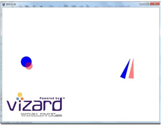
As shown in Figure 4.1, the first iteration of the BCCT used a two-dimensional, two-object visual representation to avoid ambiguities in specifying target position and orientation. All BCCT software was developed using the WorldViz Vizard integrated development environment built on top of the Python programming language.
Figure 4.1 – Early two-dimensional, two-object version of the BCCT. The operator is tasked to track the motion of a pair of blue targets on a computer screen using a pair of corresponding red cursors. The circular target on the left side translates in a circular trajectory and scales in size. To
track these fluctuations, the operator must move the THC in three corresponding axes. The triangular target on the right side translates in a circular trajectory and rotates about its center. To
track these fluctuations, the operator must move the RHC in three corresponding axes. Unfortunately, although there was no visual ambiguity per se, the separation of the command input into two objects resulted in difficulty focusing attention on both targets simultaneously.
31
Thus, movements tended to be jerky and non-continuous as the operator’s gaze switched between two locations on the computer screen. Since this behavior seemed empirically different compared to what is experienced during track and capture, and because there may be separate neural representations for bimanual control of two objects versus bimanual control of a single object [55], the software was updated to use a single-object, three-dimensional target
representation, as shown in Figure 4.2.
Figure 4.2 – Screenshot of the updated, single object, 3D BCCT display. In the trial shown, the target (more translucent, upper animal figure) was moving with a combination of roll and vertical
translation. The subject was required to simultaneously use both the THC and RHC to move the cursor (more opaque, lower animal figure) to track the target.
Although in theory, an integrated two-dimensional target will result in better performance [56], it is very difficult in our case to unambiguously represent six degrees of freedom in a single two-dimensional object. Switching to a single-object, three-two-dimensional representation causes two main problems. First, tracking in three dimensions results in large errors in the depth axis [57], even if a stereoscopic display is used [58]. Second, depending on the nature of the three-dimensional object and which axes are displaced, it may be difficult to visually discern whether a given tracking error is due to translation or rotation. Although the second problem can largely be avoided by the choice of a spatially unambiguous object, the first problem is one that we chose to tolerate, as the alternative would be to avoid motion in the depth axis by reassigning the THC depth axis to control some other aspect of the cursor. This is not a desirable solution because it would break the intuitive correspondence between the three-dimensional controls paradigm in track and capture and the similar controls in the BCCT. We are able to partially ameliorate the poor depth tracking by adding a drop line extending from the object to a planar grid which is unambiguous in depth.
32
4.1.3.2 Feedback
Our simplified model of bimanual cross-coupling (Figure 2.2) is feed forward, but clearly some visual feedback is required in a tracking task. Because we are dealing with potentially six degrees of freedom with three axes per hand and any single directional coupling ratio is defined between only two of these axes, we actually have some flexibility in not only how we choose to present visual feedback of THC and RHC deflections, but also in how we present the command inputs.
In fact, preliminary trials showed that simultaneous tracking in six degrees of freedom at the specified frequencies was far too difficult even for a well-trained subject. This was not
unexpected, since our simulated track and capture tasks never simultaneously require active motion in all six degrees of freedom, and empirically it appears that subjects only actively correct for errors in two or three degrees of freedom at a time during track and capture.
The ability to track the target effectively is important because the frequency commands present in the target motion must be passed through the subject relatively intact. Although the frequency detection can be made robust to any linear, time-invariant model of the human (i.e. an FIR representation of the human, consisting of time-invariant delays and scaling factors) that does not drastically cut off the specific command frequencies, any nonlinearities should be small enough that they do not cause significant frequency shifts.
Thus, it was decided to present target motion in only two degrees of freedom per trial, with one degree of freedom per hand, and to use multiple varied trials over the course of the entire BCCT to collect all of the coupling relationships.
4.1.4 Output Methodology
The outputs from the human in terms of both signal type and signal locations are clearly defined by our use of the same hand controllers as used in the simulated track and capture tasks. The signals consist of digital joystick readings sampled by a desktop computer at 30 Hz via the built-in Microsoft Wbuilt-indows XP™ game controller USB built-interface. The readbuilt-ings are normalized built-in the BCCT software to represent ratios of maximal hand controller displacement, and thus are a combination of mostly wrist and finger movements, depending on the motion, acting in
conjunction with the specific mechanical configuration of the THC and RHC. Musculature used is kept approximately consistent with track and capture musculature by keeping the training essentially the same.

![Figure 2.1 – A general model of why bimanual actions are coupled [2].](https://thumb-eu.123doks.com/thumbv2/123doknet/14159353.473026/11.892.155.732.510.964/figure-general-model-bimanual-actions-coupled.webp)