Treatment of Textile Wastewater using monolayered
UltrafiltationCeramic Membrane Fabricated from
Natural Kaolin Clay
Saida Bousbih, Emna Errais, Fadila Darragi, Joelle Duplay, Malika Trabelsi- Ayadi, Michael Olawale Daramola & Raja Ben Amar
Treatment of Textile Wastewater using monolayered UltrafiltationCeramic
Membrane Fabricated from Natural Kaolin Clay
Saida Bousbiha, Emna Erraisb, Fadila Darragia, Joelle Duplayc,
Malika Trabelsi – Ayadia, Michael Olawale Daramolad and Raja Ben Amare*.
aLaboratoire des applications de la Chimie aux ressources et substances naturelles et à l'environnement
(LACRESNE).Faculté des sciences de Bizerte, Université de Carthage,Tunisia.
bLaboratoire Physique des Matériaux Lamellaires et Nanomatériaux Hybrides .Faculté des sciences de Bizerte, Université de
Carthage,Tunisia.
cLaboratoire d’hydrologie et de géochimie de Strasbourg, France.
dSchool of Chemical and Metallurgical Engineering, Faculty of Engineering and the Built Environment, University of the
Witwatersrand, Wits2050, Johannesburg, South Africa.
eLaboratoire Sciences des Matériaux et Environnement.Faculté des Sciences de Sfax, Université de Sfax,Tunisia.
Corresponding author : (Raja Ben Amar).benamar.raja@yahoo.com raja.rekik@fss.rnu.tn
Abstract
Fabrication,characterization and application of ceramic membrane developed from Tunisian natural kaolin clay for textile wastewater treatment are presented in this study.The morphology and properties of the resulting membrane sintered at 1000°C for 3 h was then determined by Scanning Electron Microscopy (SEM),mechanical and chemical resistance and water permeability.Separation performance of the membrane was evaluated during treatment of textile wastewater.SEM images reveal homogeneous surface of the membrane.The membrane displayed good chemical and mechanical resistances as well. Its permeability was of 21.2 L.h -1.m-2.bar-1, indicating that separation performance could occur in the domain of Ultrafiltration(UF).Performances of the membrane during the treatment of raw and biologically pretreated textile effluents are promising in terms of removal of color (99% for the raw effluent and 100% for the biologically pretreated effluent), chemical oxygen demand (COD) (80% for the raw effluent and 93% for the biologically pretreated effluent) and turbidity (98% for the raw effluent and 100% for the biologically pretreated effluent).
Keywords: Natural kaolin clay, Ceramic membrane, Ultrafiltration, Textile industry wastewater.
I. Introduction
Porous ceramic membranes have many advantages ,such as suitable properties in terms of thermal resistances, mechanical and chemical resistance [1,2], long life time and ease of cleaning [3,4].These membranes are generally manufactured from inorganic compounds such as alumina (Al2O3),silica (SiO2), zirconia (ZrO2) and titania (TiO2). However, the use of these
materials is expensive [5].
To circumvent the issue of high cost of these materials that result in high production cost of ceramic membranes, many recent research activities have focused on the preparation of ceramic membranes from natural materials such as phosphate [6], zeolite [7,8], carbon [9],
fly ash [10,11] and clay [12-14].
In the context of the use of clay as a raw material for ceramic membrane preparation, natural kaolin clay has been identified as one of the promising materials [15] because it offers high strength and low plasticity, as well as good hydrophilicity to membrane [16].Furthermore, kaolin is a preferred starting material for developing ceramic membranes for water filtration because of its good mineralogical properties, its chemical composition as well as particle size that make development of good porous membranes easy and possible [17].
Many researchers have investigated the use of kaolin and natural clay as starting materials together with other additives for membrane preparation [18]. Mohtor and al [19] have fabricated kaolin UF hollow fiber membranes and tested them for the treatment of reactive black5 (RB5) dye solution. For the same purpose, Bourdaira and al [20] developed tubular support for MF and UF membranes from local kaolin and calcium carbonate mixtures.
Fatimah and al [21] also reported the development of ceramic membranes from TiO2 for
microfiltration and ultrafiltration. Furthermore, several researchers have reported the use of kaolin for the development of membranes with the addition of other materials. Thus, Guechi and al [22] prepared tubular ceramic support from a mixture of low cost Algerian kaolin and calcium carbonate at a sintered temperature of 1100˚C. It is evident that advent of membrane technology has revolutionized the water treatment sector and has been considered as a viable alternative for water reclamation in the textile industry.However to make the technology more economical in terms of membrane production cost, local and cheap materials should be explored in the development of the ceramic membrane.The membrane materials should
produce membrane with high separation performance process and competitive with commercially available membranes obtained from conventional materials. In addition, the membrane materials should be adaptable to different steps involved in the treatment of different effluents and should be scalable to fast-track the commercialization of the materials for water reuse and management [23].Recently, the use of local materials in the development of membranes for different applications has been applauded in the research area because of its effectiveness in reducing membrane production cost [24-26].Therefore,in this study,an ultrafiltration (UF) ceramic membrane was developed from Tunisian natural Kaolin clay and applied to the treatment of raw and biologically pre-treated textile effluent. As far as could be ascertained, no reports have appeared in literature on the development of low-cost UF ceramic membrane containing only one separative layer from natural kaolin, especially Tunisian kaolin.
II. Materials and methods II.1. Materials
The clay used was obtained from Sidi Badr deposit (locality of Tabarka) located in the North - West of Tunisia. The clay powder was sieved at 250 μm.
Additives employed in the membrane preparation were : Amijel (C plus 12076, Cerestar) as plasticizer, Methocel (Dow Chemical Company) as binder and Starch (Cerestar RG 03408) as porosity agent. The composition of the resulting paste as reported from a previous study and used in this study was 84% (w/w) clay, 8% (w/w) starch, 4% (w/w) Methocel and 4% (w/w) Amijel [27]. The textile wastewater effluent was provided by a local company. Two types of effluents were used : raw effluent coming from the dyeing process and biologically pretreated effluent (obtained after biological treatment by activated sludge) (see section 3 for the composition).
The wastewaters were characterized and checked for the following parameters: conductivity (using a conductimeter Tacussel model 123), pH (using a pH meter, Metrohm 744 pH-meter), turbidity (using a turbidimeter, Hach Ratio 2100 A), chemical oxygen demand (COD) (using a standard COD kit) and color intensity (using a UV spectrophotometer, UV-9200).
II.2. Clay powder characterization
The clay powder was characterized using different techniques. Phase identification was performed using XRD diffractometer (Bruker D5000). The chemical composition of the clay was determined by X-ray fluorescence. A thermogravimetric analysis instrument (TGA 2950 model, SDT Q600) was used to study the thermal degradation behaviour of the sample under
argon and at a heating rate of 5° C / min from room temperature to 1100 °C. Fourier- transform infrared (FTIR) analysis was performed with NICOLET IS10 Thermo-Scientific spectrometer equipped with a Globar source and a DTGS detector (wavenumber ranged from 400 cm-1 – 4000 cm-1).
II.3. Membrane synthesis and characterization
Procedure for the perapation of the tubuar membrane is illustrated in Figure 1.The preparation of the homogeneous paste was carried out with a mixture of 400 g of mixture of clay, organic additives in powder and distilled water. After a day of aging, the paste was extruded into tubes of 6 mm internal diameter.The extruded tubes were dried and then sintered to obtain a consolidated ceramic membrane. A two-step program was defined: the first for the removal of organic additives at 300°C for 2 h and the second for sintering at different temperatures for 3h.
Figure1. Different steps involved in the production of the tubular ceramic membrane via extrusion.
The surface morphology of the fabricated membrane was checked by using a scanning electron microscope (Zeiss MERLIN SEM). The mechanical resistance tests were performed using the three points bending method (with LLOYD Instrument) to control the resistance of the obtained membranes at different temperatures during sintering.The chemical resistance tests were carried out using aqueous solutions of 0.5 M NaOH (pH = 12) and 0.2 M HNO3
(pH = 3). The sample was soaked at 80 °C and the weight loss was controlled for 3 days. The degree of corrosion was characterized by the percentage of the weight loss.The pore size
distribution of the membrane was obtained via nitrogen physisorption experiments at 77 K using a Micromeritics analyzer (model : ASAP 2020 V4.02 Instruments).
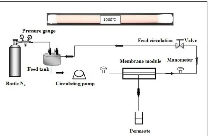
Membrane permeability was evaluated at room temperature and a transmembrane pressure (TMP) ranging between 3 and 7 bar using a home-made pilot plant (Figure 2).Before the tests, the membrane was conditioned by immersion in distillated water for at least 24 h.
The transmembrane pressure (TMP) was controlled by a valve on the retentate side.The determination of the original membrane permeability was performed using distilled water.
Figure 2. Schematic representation of the home-made Ultrafiltration setup.
II.4. Membrane performance using textile wastewater
The treatment of textile effluents (raw effluent and biologically treated effluent) using the low cost membrane was done under a transmembrane pressure (TMP) from 3 to 7 bars with superficial velocity of 1.76 m/s.The rejection (selectivity) of the membrane in terms of COD, turbidity and color, was evaluated using Equation (1) :
� % = [1 − ( ���
� )] × 100 (1)
Where Cf and Cp are the concentration in the feed and permeate, respectively. R is the
II. Membrane regeneration
Only Distilled water was used for the membrane regeneration without any chemicals additives. The duration of each regeneration cycle was 20 minutes followed by membrane resistance determination. The total number of regeneration cycle was determined when the obtained flux after repeated regeneration is similar to that of the unused membrane.
Fouling (reversible or irreversible) is often the major obstacle to the use of membrane processes [28]. In general, reversible fouling may be attributed to concentration polarization and deposition of the rejected substances on the surface of the membrane. This type of fouling can be easily removed by a simple backflushing of the fouled membrane with water or by changing some of operating variables. The irreversible fouling results from internal clogging of the pores by organic or inorganic foulants and requires chemical cleaning [29]. Several models have been developed to describe the fouling mechanism in membrane processes such as the resistance-in-series model (Equation 2) which was employed in this study.
�� = � � + �� � � + �� �(2)
Where RT is the total resistance obtained during the filtration tests in the presence of the
effluent (m-1) ;
Rm is the inherent hydraulic resistance (m-1) due to the membrane, and obtained from the
water permeability test ;
Rrev and Rirrev are the resistance from reversible and irreversible fouling, respectively (m-1).
III. Modelling of membrane fouling
According to Hermia's model [30], the fouling-dominating mechanism in the whole process can be predicted using permeate volume (V) and treatment time (t). The linearity of the t/V versusV curve shows that the main mechanism of fouling is cake formation. However, the linearity of the t/V versus t curve and the ln (t) vs V curve show that the standard and intermediate blocking models can represent the dominant fouling mechanism. Hermia has developed equation (3) to predict the time of each fouling mechanism :
�²� = � ( � �²
� � �
) (3)
*LOI: loss on ignition
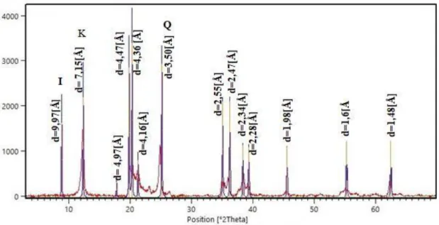
The X-ray diffraction (XRD) pattern of the Tabarka clay (Figure 3) shows the following composition: Kaolinite (61%) and illite (39%). The non-clay minerals are represented essentially by quartz.
Where V is the volume of the permeate at time t and k is the coefficient depending on the flow rate and solution properties. The parameter n is a constant depending on the fouling mechanism involved in the system.
IV. Results and discussion
SiO2 Al2O3 CaO Fe 2O3
MgO Na2O K2O SO3 *LOI
55.25 24.17 0.16 1.15 5.39 0.19 1.78 0.4 9.77
Figure 3. X-Ray diffraction diagram of the Tabarka clay.
IV.1. Physico-chemical and thermal characterization of clay powder
The chemical composition of the clay in weight percentages of oxides (Table 1) reveals that the clay powder is composed of large amount of silica (55.25 %) and alumina (24.17 %) with other oxides like calcium oxide, magnesium oxide, potassium oxide etc. in trace amounts.
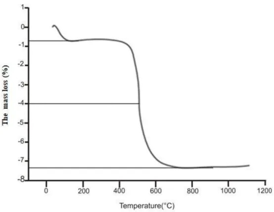
Four main decomposition stages are distinguishable from the TGA (Figure 4).Between 100 and 150°C, an endothermic peak (of about 0.76%) appears which corresponds to dehydration and the release of adsorbed water. The second stage, located at 530°C (of about 4%), could be attributed to the dehydroxylation of clay minerals and the destruction of kaolinite.
The third stage, observed at about 800°C corresponds to an endothermic decomposition due to decarbonation.The last stage at about 960°C, represented by an exothermic decomposition correspond to phase transformation of illite, metakaolinite and mullite. This transformation does not cause any loss of mass. The total mass loss was of 7.4%.
Figure 4. TGA analysis of Tabarka clay.
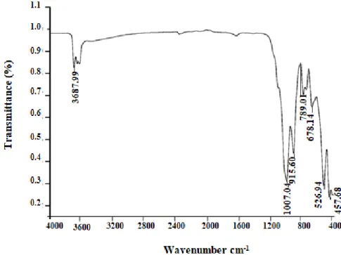
The IR spectra of the natural clay (Figure 5) show the vibration modes with different intensities.The adsorption bands observed at 3360 cm-1and at 1640cm-1 are attributed to the vibration of the OH group of hydration water of the clay lattice.Warp vibration bands at
470,540 and 457cm-1correspond to the Si-O-Mg, Si-O-Al, and Si-O-Fe groups, respectively.
Valence vibration strips (Al-Al-OH) located at 3622 cm-1and those of deformation at 916 cm-1
,do not indicate the dioctaedrique character [31].The strong band located at 1036 cm-1
characterizes the vibration in the plane and off-plan of Si-O [32].The both bands located at
680cm-1and 788 cm-1are characteristic of quartz and considered as impurity located in the clay
Figure 5. Infrared spectrum of Tabarka clay.
IV.2 Membrane Characterization
IV.2.1 Scanning Electron Microscopy(SEM)
SEM images (surface view) of the sintered membrane at 950°C ,1000°C and 1050°C (Figure 6) show a densification of the support surface with closure of the pores when the temperature increased.
The formation of the grain boundaries was achieved in this narrow temperature range.By comparing the SEM micrographs of 950°C, 1000°C and 1050°C, there is a significant change in the density of the sintered material.
The image obtained at 1000°C presents a good homogeneous structure. At 1050°C, the glassy phase was reached.
Figure 6.SEM images of the membranes sintered at (950°C, 1000°C and 1050 °C).
IV.2.2 Mechanical property of the membranes
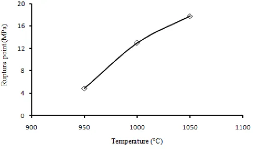
Figure 7 shows the variation of tensile strength with sintering temperature. In accordance with the SEM images, the increase of the sintering temperature is accompanied with a densification phenomenon (to obtain a more homogeneous surface) and consequently an increase in the tensile strength (from 4.84MPa at 950°C to13MPa at 1000° C).
Figure 7. Mechanical property (traction) according to the ambient temperature.
IV.2.3 Chemical resistance of the membrane
The cleaning and disinfection operations are necessary steps in membrane process for membrane regeneration.Usually, the chemical cleaning process needs the use of solutions containing suitable chemicals (acids, alkaline, etc) [33].
The membrane sintered at 1000 °C was subjected to chemical resistance tests during 72 hours. Figure 8 shows that the change in weight loss over time does not exceed 1% in both media. Indeed, the weight loss is <0.9 wt% in acidic medium and <0.6 wt% in basic medium.
Therefore,the observed results suggest that the developed membrane possesses good chemical resistance and it is suitable for applications involving acidic and basic media.These results corroborate the findings from previous studies [34-35].
From the analyses, it appears that the membrane sintered at 1000°C for 3h displayed the best mechanical and chemical properties.This membrane was then employed for the subsequent investigations.
Figure 8. Evolution of the weight loss of the membrane in acidic and basic media with time.
IV.2.4 Pore size distribution
The pore size distribution of the sintered membrane at 1000°C was determined using the BET technique based on nitrogensorption measurements (adsorption–desorption isotherm) (Figure 9).
The BET isotherms for this membrane exhibit a IV type adsorption /desorption with hystherisis loop, indicating the presence of meso- and microporous strucrtures [36].
Figure 9. Nitrogen adsorption–desorption pore size distribution of membrane sintered at 1000°C.
The mean pore diameter is 35 nm, this value demonstrated that the fabricated membrane corresponds to the domain of ultrafiltration (Figure 10).
Figure 10. Distribution of the pore size for the membrane sintered at 1000 °C from nitrogen adsorption– desorption isotherm.
IV.2.5. Determination of the membrane permeability
To obtain a rapid stability of the permeate flux, the membrane was soaked in distilled water for 24 hours before use. Figure11 shows the water permeate flux as a function of the operating transmembrane pressure (TMP). The permeate flux increased linearly with increasing applied pressure which is in agreement with the Darcy’s law [37].
The permeability of the membrane was 21.2 L.h-1.m-2.bar-1.This value is relatively low and confirmed that this membrane operates in the ultrafiltration domain.
IV.3. Separation performance during treatment of textile industry wastewater
The membrane sintered at 1000°C was employed in the treatment of textile industry raw and biologically pretreated wastewaters.Table 2 provides information about the composition of the tested wastewater.The treatment was carried out at room temperature and at TMP of 3 bars, 5 bars and 7 bars. Figures 12 and 13 illustrate the behavior observed during ultrafiltration of the raw and the biologically pre-treated effluent respectively. Figure12 (a) shows that the permeate flux increased linearly with the pressure.This behaviour indicates that the mass transfer is controlled by the convection (no clogging of the pores).
From Figure 12 (b), a decrease of the permeate flux from 32 L.h-1.m-2 to 28 L.h-1.m-2during the first 30 min at 5 bars was observed. At 3 bars, a quasi-stabilisation of the flux was
obtained at about 19 L.h-1.m-2. A similar behaviour was recorded with biologically pretreated
effluent (Figures 13 (a) and 13 (b)).However, the determination of the permeate flux demonstrated a significantly higher values compared with that obtained with the raw efflent. A quasistabilized flux of 50 L.h-1.m-2 and 30 L.h-1.m-2 were observed respectively for 5 and 3 bars, indicating the effect of the pretreatment on the enhancement of the membrane separation performance.
(b)
Figure 12. Permeate fluxes as a function of pressure (a) and time (b) for the raw effluent. (a)
Sample pH Conductivity (mS/cm) Turbidity (NTU) COD (mgl-1) Color (Abs.λ590nm) Raw effluent 12.5 6.25 576.0 2075.0 1. 836 Biologically pre-treated 8.5 5.60 198.5 147.5 1.132 effluent Permeate (P=5bar) 12.2 3.97 2.9 410 0.041 Raw effluent 36.48% 99.49% 80.24% 98% Permeate (P=5bar) 8.3 2.8 0.9 10 - Pre-treated effluent 50% 99.54% 93%
A high rejection capacity for the membranes using both types of wastewater was observed.An approximately total rejection for all the pollutants was obtained during the treatment of the biologically-pretreated effluent.
With the raw effluent, the rejection for COD, color,conductivity and turbidity observed at 5 bars were 80,98%,36.48% and 99% respectively.When the biologically-pretreated effluent was considered, these values varied as 93% ,100%, 50% and 100%.
(a) (b)
Figure13. Permeate fluxes as a function of pressure (a) and time(b) for the biologically- preteated effluent.
Table 2 shows the main characteristics of the different effluents after the membtane treatment. A significant decrease of the different pollutants values was observed. The turbidity and the color are clearly lowered by the membrane treatment, mostly in the case of the pretreated effluent showing an absence of color and a much reduced turbidity value (0.9 NTU).
Aloulou and al [38] reported the treatment of similar raw textile effluent using a nanocomposite clay/Titania (Sm/Z) UF ceramic membrane.
They found that this synthesis UF membrane displayed rejection of 87.35% and 46.08 % respectively for COD and conductivity, however a high rejection of 95.35% and 99.52% for color and turbidity was observed in the same time. Therefore, it is evident that the membrane elaborated in this study has a characteristics that outperforms other developed UF ceramic membranes.On the other hand,according to Khemakhem and al [39],a low cost phosphate
based UF ceramic membrane having a water permeability of 90 L.h-1.m-2.bar -1 was developed
and applied succesfully to the treatment of textile effluent providing 90% COD removal and a total retention of color.
IV.4. Membrane fouling, regeneration and modelling IV.4.1. Membrane fouling and regeneration
The different resistances calculated are summarized in Table 3.It can be concluded that the reversible fouling is the dominant fouling mechanism during the treatment of both the raw
and the biologically-pretreated effluents (Rirr<Rrev).Therefore,the membrane could be cleaned
by simple hydraulic backwashing using distilled/de-ionized water and followed by chemically-enhanced washing for 100% recovery of the original membrane flux as reported else where [41].
Table3: Estimated resistances from the resistances-in-series model.
Textile effluent RTx1012 (m-1) Rmx 1012 (m -1) Rrev x1012 (m-1) Rirr x1012 (m-1) Raw effluent 5.834 1.74 2.099 1.99 Biologically-pre- treated effluent 3.80 1.74 1.917 0.138
recovery of the membrane flux was observed after the 3rd cleaning cycle after using the raw effluent (Figure 14).
The regeneration of the membrane was carried out by simple backwashing with distilled water after each use. This procedure was repeated for three cycles (after the raw effluent stream treatment), and two cycles (after the treatment of the biologically-pretreated effluent stream). The effectiveness of the regeneration was verified by determining the water permeability of the membrane, which should be very close to the original permeability of the new membrane. From Figure 15, a slight loss of membrane performance until the 2nd cleaning cycle was observed after the biologically-pretreated effluent treatment.But approximately, a total
Figure 14. Membrane regeneration after the treatment of the raw effluent.
Figure 15. Membrane regeneration after the treatment of the biologically-pre-treated effluent.
IV.4.2. Fouling modelling
The transport mechanism through membrane pores is largely affected by the development of concentration boundary layer, which is generally caused by the membrane fouling, where partial blocking of membrane pores may take place.Therefore, it is important to study the origin of the decline of the permeate flux during the filtration process.
To understand this phenomenon, theoretical models for membrane fouling such as standar pore blocking model (Figure16), the pore narrowing model (Figure 17) and the cake filtration model (Figure 18) are used [42,43].
In this study, these models were used to understand the fouling behaviour of the membrane in the presence of both types of effluents, under ambient temperature and transmembrane pressure of 5 bars. It can be observed tha the fouling of the membrane could well be described by the cake fitration model (Figure 18). This behaviour can be explained by the deposition of particles larger than the membrane pore size onto the membrane surface.These results are in agreement with the results from the resitance-in-series model showing that reversible fouling is pronounced during the treatment of both effluent. In this context, Fersi and al [44] reported that a rapid cake formation occurs for MF and UF during the treatment of textile effluent with a sharp drop in membrane flux at the early stage of the treatment.
Figure 17. Fouling behaviour of the membrane using pore-narrowing model.
Figure18. Fouling behaviour of the membrane using cake-filtration model.
V. Conclusion
In this study, a new UF ceramic membrane fabricated from natural Tunisian Kaolin clay has been developed and evaluated for the treatment of textile industry wastewater.The mineralogical composition of the natural clay shows a high percentage of kaolinite (61%) mostly composed of alumina and silica.
The synthesized membrane displayed good mechanical and chemical properties when sintered at a temperature of 1000°C.The BET analysis indicates a mean pore size of 35 nm indicating
The application of the membrane to the treatment of raw and biologically-pretreated textile effluents shows a quasi-stabilisation of the permeate flux after 30 minutes of filtration in the TMP range (3-7 bars). At 5 bars, the permate flux was 28L.h-1.m-2 and 50L.h-1.m-2, respectively for the raw and the biologically-pretreated effluent.
During the UF treatment, the membrane displayed good rejection in terms of color, COD and turbidity. The study shows that the reversible fouling is dominant and that membrane fouling given by the decline of the permeate flux with the time, could be described by the cake- filtration model.
Acknowledgment
The authors would like to thank the ERANETMED program (SETPROpER) for funding the entire research work.
References
[1] Wang B, Lai Z. Finger-like voids induced by viscous fingering during phase inversion of alumina/PES/NMP suspensions.Journal of membrane science, Elsevier Journal of Membrane Science. 2012 ; 405–406: 275-283.
[2] Sarkar S, Bandyopadhyaya S, Larbot A, Cerneaux S. New clay–alumina porous capillary supports for filtration application. J. Membr. Sci. 2012 ; 392-393 : 130–136.
[3] Monash P, Pugazhenthi G.Effect of TiO2 addition on the fabrication of ceramic membrane
supports:a study on the separation of oil droplets and bovine serum albumin (BSA) from its solution. Desalination.2011 ; 279 : 104-114.
[4] Han JH, Oh E, Bae B, Song IH. The fabrication and characterization of sintered diatomite for potential microfiltration for applications.Ceramics International. 2013 ; 39 : 7641- 7648. [5]Talidi A, Saffaj N, El Kacemi K, Younssi SA, Albizane A, Chakir A .Processing and characterization of tubular ceramic support for microfiltration membrane prepared from pyrophyllite clay.Scientific Study & Research Chemistry & Chemical Engineering, Biotechnology, Food Industry. 2011 ; 12 (3) : 263 – 268.
[6] Khemakhem M, Khemakhem S, Ayedi S, Cretin M, Ben Amar R. Development of an asymmetric ultrafiltration membrane based on phosphates industry sub-products. Ceram Int .2015 ; 49: 10343-10348.
[7] Mastropietro TF, Drioli E, Candamano S, Poeriob T.Crystallization and assembling of FAU nanozeolites on porous ceramic supports for zeolite membrane synthesis, Microporous Mesoporous Mater.2016 ; 228 :141–146.
[8] Aloulou H, Bouhame H, Ghorbel A, Ben Amar R, Khemakhem S. Elaboration and characterization of ceramic microfiltration membranes from natural zeolite: application to the treatment of cuttlefish effluents.J Desalination and Water Treatment. 2017:1–9.
[9] Tahri N, Jedidi I, Cerneaux S, Cretin M, Ben Amar R .Development of an asymmetric carbon microfiltration membrane: application to the treatment of industrial textile wastewater, Sep. Purif. Technol.2013 ; 118 :179–187.
[10] Cao J, Dong X, Li L, Dong Y, Hampshire S. Recycling of waste fly ash for production of porous mullite ceramic membrane supports with increased porosity. Journal of the European Ceramic Society. 2014 ; 34 : 3181–3194.
[11] Fang J, Qin G, Wei W, Zhao X .Preparation and characterization of tubular supported ceramic microfiltration membranes from fly ash.Separation and Purification Technology. 2011 ; 80 :585–591.
[12] Emani S, Uppaluri R, Purkait MK. Preparation and characterization of low cost ceramic membranes for mosambi juice clarification. Desalination.2013 ; 317: 32-40.
[13] Palacio L, Bouzerdi Y, Ouammou M, Albizane A, Bennazha J, Hernández A, Calvo J. I. Ceramic membranes from Moroccan natural clay and phosphate for industrial water treatment. Desalination.2009 ; 245 : 501-507.
[14] Jana S, Purkait MK, Mohanty K. Preparation and characterization of low-cost ceramic microfiltration membranes for the removal of chromate from aqueous solutions. Appl Clay Sci .2010 ; 47: 317-324.
[15] Ganesh I, Ferreira J.M.F. Influence of rawmaterial type and of the overall chemical composition on phase formation and sintered microstructure of mullite aggregates. Ceram. Int. 2009 ; 35 : 2007–2015.
[16] Mgbemena CO, Ibekwe NO, Sukumar R, Menon ARR. Characterization of kaolin intercalates of oleochemicals derived from rubber seed (Hevea brasiliensis) and tea seed (Camelia sinensis) oils, J. King Saud. Univ. - Sci. 2013 ; 25 : 149–155.
[17] Hedfi I, Hamdi N, Srasra E, Rodríguez MA. The preparation of micro-porous membrane from a Tunisian kaolin, Appl. Clay Sci. 2014 ; 101 : 574–578.
[18] Parma S, Chowdhury P .Preparation and characterization of microfiltration ceramic membrane for oily waste water treatment.J International Journal of Research in Engineering
[19] Hamizah Mohtor N, Dzarfan Othman MH, Ismail AF, Mukhlis A. Rahman, Jaafar J,A wanis Hashim N. Investigation on the effect of sintering temperature on kaolin hollow fibre membrane for dye filtration.J Environ Sci Pollut Res .2017 ; 24:15905–15917.
[20] Boudaira B, Harabi A, Bouzerara F, Zenikheri F, Foughali L and Guechi A .Preparation and characterization of membrane supports for microfiltration and ultrafiltration using kaolin
(DD2) and CaCO3.J Desalination and Water Treatment.2015 ; 1944-3994.
[21] Fatimah I, Sahroni I, Purnama Putra H , Rifky Nugraha M , Uun Ayil Hasanah . Ceramic membrane based on TiO2-modified kaolinite as a low cost material for water filtration
.J Applied Clay Science .2015; 118 : 207–211.
[22] Guechi A, Harabi A, Condoum S, Zenikheri F, Boudaira B, Bouzerara F,
Foughali L. Elaboration and characterization of tubular supports for membranes filtration.J Desalination and Water Treatment .2015 ;57(12): 1–7.
[23] Masmoudi G, Trabelsi R, Ellouze E, Ben Amar R. New treatment at source approach using combination of MF and NF for dyeing effluents reuse.International Journal of Environmental Science and Technology .2014; 11:1007-1016.
[24] Ayadi S, Jedidi I,Cretin M,Cerneau S, Ben Amar R. Preparation and Characterization of Carbon Microfiltration Membrane Applied to the treatment of textile industry effluents, Separation Science and Technology.2016;51:1022-1029.
[25] Sayehi M, Dhouib Sahnoun R, Fakhfakh S, Baklouti S.Eff�ect of elaboration parameters of a membrane ceramic on the filtration process efficacy.Ceramics International.2018;44: 5202–5208.
[26] Iaich S,Messaoudi L.Preparation of new ceramic supports macro-porous for
microfiltration and ultrafiltration membranes based Moroccan clay. Mechanical and Civil Engineering.2014 ; 11: 56-62.
[27] Khemakhem S, Ben Amar R, Larbot A. Nouvelles membranes de microfiltration en céramique à partir de matériaux naturels tunisiens: Application au traitement des effluents de seiche. Ceramics International, 2009.35: 55-61.
[28] Tahri N,Masmoudi G, Ellouze E, A.rad J, Drogui P, Ben Amar R.Coupling
microfiltration and nanofiltration processes for the treatment at source of dyeing containing effluent. Journal of cleaner production. 2012 ; 33 :226-235.
[29] Tansel B, Bao WY, Tansel IN. Characterization of fouling kinetics in ultrafiltration systems by resistances in series model. Desalination.2000; 129:7-14.
[30] Hermia J. Constant pressure blocking filtration laws - Application to power-law non- Newtonian fluids. Trans. Inst. Chem. Eng.1982; 60(3):183-187.
[31] Rakib S, Sghyar M, Rafiq M, Larbot A .Cot L. Elaboration et caracterisation d’une ceramique marcroporeuse à base d’arène granitique. Ann Chim Sci Mat. 2000 ; 25 : 567–576. [32] Farmer VC, Russell JD. The infra-red spectra of layer silicates. Spectrochimica Acta, 1964; 20(7):1149–1173.
[33] Gan Q, Howell J.A, Field R.W, R. England, M.R. Bird, M.T.McKechinie .Synergetic cleaning procedure for a ceramic membrane fouled by beer micro-filtration. J Membr Sci. 1999 ; 155 : 277–289.
[34] Sayehi M, Dhouib Sahnoun R, Fakhfakh S, Baklouti S .Eff�ect of elaboration parameters of a membrane ceramic on the filtration process efficacy .Ceramics International 2018;44: 5202–5208
[35] Khemakhem S, Larbot A, Ben Amar R.New ceramic microfiltration membranes from Tunisian natural materials: Application for the cuttlefish effluents treatment.Ceramics International 2009; 35: 55–61.
[36] Tahri N, Jedidi I, Cerneaux S, Marc Cretin M, Ben Amar R.Development of an asymmetric carbon microfiltration membrane:Application to the treatment of industrial textile wastewater.Separation and Purification Technology 2013; 118: 179–187.
[37] Khemakhem S, Ben Amar R, Ben Hassen R, Larbot A, Ben Salah A and Cot L.Production of tubular ceramic membranes for microfiltration and ultrafiltration.Indust Ceramics. 2004; 24(3):117–120.
[38] Aloulou W, Hamza W, Aloulou H, Ouna A,Khemakhem S ,Jada A,Chakraborty S, Curcio S,Ben Amar R.Developing of titania-smectite nanocomposites UF membrane over zeolite based ceramic support .Applied Clay Science . 2018; 155: 20–29.
[39] Tahri N,Jedidi I,Cerneau S,Cretin M,Ben Amar R.Preparation of an asymmetric microporous carbon membrane for ultrafiltration separation: Application to the treatment of industrial dyeing effluent,Desalination and Water Treatment.2016; 57(50):23473-23488. [40] Khemakhem M, Khemakhem S, Ayadi S, Cretin M, Ben Amar R. Development of an asymmetric ultrafiltration membrane based on phosphates industry sub-products. Ceramics International.2015 ; 41 : 10343–10348.
[41] Daramola MO, Adeogun AG. Empirical modelling of chemically enhanced backwash during ultrafiltration process .Membrane Water Treatment 2011; 2(4): 225-237.
[42] Aliasghari Aghdam M, Mirsaeedghazi H, Aboonajmi M, Kianmehr MH. Effect of ultrasound on different mechanisms of fouling during membrane clarification of pomegranate juice. Innovative Food Science & Emerging Technologies.2015; 30:127-131.
[43] Hou L ,Wang Z, Song P. A precise combined complete blocking and cake filtration model for describing the flux variation in membrane filtration process with BSA solution. Journal of Membrane Science. 2017 ; 542 : 186-194.
[44] Fersi Ch, Gzara L, Dhahbi M. Flux decline study for textile wastewater treatment by membrane processes. Desalination .2009 ; 244 :321–332.
raw effluent
Membrane- treated