PSFC/RR-97-9
Approaches to Quench Protection
Joel H. Schultz May 19, 1997
Plasma Science and Fusion Center Massachusetts Institute of Technology
Cambridge, MA 02139 USA
This work was supported by the U.S. Department of Energy Contract No. DE-AC02-76-CH03073. Reproduction, translation, publication, use and disposal, in whole or in part by or for the United States government is permitted.
Approaches to Quench Protection Joel H. Schultz
M.I.T. PFC Report/ PSFC/RR-97-9 May 19, 1997
ABSTRACT
Superconducting magnets are subject to a thermal instability, leading to the loss of superconductivity, known as "quench," in which the critical values of field, temperature, and current density are exceeded and fail to recover. This phenomenon generally begins in a localized region of the coil, then spreads to the rest of the magnet or magnet system with a "quench propagation velocity." All magnets use some form of composite superconducting wire, in which superconducting filaments carry current in parallel with normal conductor, known as the stabilizer. The stabilizer has the dual purpose of preventing quench in the face of disturbances and of protecting the magnet from excessive temperatures and pressures when unwanted quenches occur. Following a quench, current rapidly transfers from the superconducting material to the stabilizer, since composites are always designed so that the resistance of the stabilizer is much less than that of the superconducting material in its normal state.
In the case of a quench, it is almost never possible to allow continued operation at constant current without unacceptable temperature rises in the magnets. The current must be reduced to zero and the stored energy in the magnet eliminated, either by absorbing the energy within the magnet or by dumping the energy externally. If the energy is dumped externally, it may be absorbed in either warm, generally room temperature, dump circuits, or in cold, generally liquid helium temperature, dump circuits. Some magnets have
sufficient enthalpy in their stabilizer and coupled passive structures to absorb their own stored energy without excessive temperature or pressure rises. Most magnets have
sufficient enthalpy, so long as the ratio of peak local heating to average global heating can be held to acceptably low levels. The peak/average ratio can be controlled by design either by activating internal resistive or inductive heaters or by rapidly dumping or heating all helium coolant in order to guarantee that large portions of the coil will heat up together. The other method of protecting magnets is to dump the magnet energy into an external resistor. This requires an absolutely reliable method of interrupting current flow from the power supply and diverting it into the dump resistor. Both methods require reliable and rapid detection of a quench.
Approaches to Quench Protection Joel H. Schultz
M.I.T. Plasma Science and Fusion Center Cambridge, MA
Superconducting magnets are subject to a thermal instability, leading to the loss of superconductivity, known as "quench," in which the critical values of field,
temperature, and current density are exceeded and fail to recover. This
phenomenon generally begins in a localized region of the coil, then spreads to the rest of the magnet or magnet system with a "quench propagation velocity." All magnets use some form of composite superconducting wire, in which
superconducting filaments carry current in parallel with normal conductor, known as the stabilizer. (In this paper, we use the word "normal" to mean "not
superconducting" and also to refer to routine, as designed magnet operation. The meaning should be obvious from the context.) The stabilizer has the dual purpose of preventing quench in the face of disturbances (cf. Bottura and Luongo, this volume) and of protecting the magnet from excessive temperatures and pressures when unwanted quenches occur. Following a quench, current rapidly transfers from the superconducting material to the stabilizer, since composites are always designed so that the resistance of the stabilizer is much less than that of the superconducting material in its normal state.
In the case of a quench, it is almost never possible to allow continued operation at constant current without unacceptable temperature rises in the magnets. The current must be reduced to zero and the stored energy in the magnet eliminated, either by absorbing the energy within the magnet or by dumping the energy
externally. If the energy is dumped externally, it may be absorbed in either warm, generally room temperature, dump circuits, or in cold, generally liquid helium temperature, dump circuits. Some magnets have sufficient enthalpy in their
stabilizer and coupled passive structures to absorb their own stored energy without excessive temperature or pressure rises. In fact, most magnets have sufficient enthalpy, so long as the ratio of peak local heating to average global heating can be held to acceptably low levels. The peak/average ratio can be controlled by design either by activating internal resistive or inductive heaters or by rapidly dumping or heating all helium coolant in order to guarantee that large portions of the coil will heat up together. The other method of protecting magnets is to dump the magnet energy into an external resistor. This requires an absolutely reliable method of interrupting current flow from the power supply and diverting it into the dump resistor. Both methods require reliable and rapid detection of a quench.
The fundamental limit on protecting magnets against quench is the detection of that quench. This can be particularly difficult in the case of coils in an
electromagnetically noisy environment, pulsed coils, and multicoil systems. It is also difficult when the coils are very conservatively stabilized, as is often the case for very large coil systems and buswork. Quench detection systems can be active or passive. Active systems usually involve some sort of balanced voltage bridge. The signal/noise ratios of voltage bridges can be improved by using cowound sensors and active cancellation. Passive systems use transformer-fed heaters to trigger
In order to size a magnet for protection, it is usually necessary to know something about the physics of quench propagation. Different physical theories are needed to predict the spread of quench in potted, pool-boiling, and cable-in-conduit
superconductors (CICC). Because of the difficulties in predicting disturbances, initial quench zones, and quench propagation, a conservative design criterion is to assume that local hot spots are adiabatic and that all energy must be dumped externally. For internal quenching, the maximum time to heat a long quench zone with a cowound or surface heater has to be known.
The problem of magnet quench protection is a subset of the generic problem of magnet protection, (1) during normal operation, (2) off-normal conditions such as quench, and (3) faults, whether in the coil, bus, or power supply. The two most fatal flaws are mechanical rupture and electrical arcing. They are often preceded by excessive displacement and/or partial electrical discharges and leakage currents. Flaws that are sometime repairable can end a magnet's useful life when cracks cause leakage of helium under pressure, leakage current causes enough heat to quench the magnet, or displacements create unacceptable field errors. All of structural design may be considered as part of the magnet protection design. This subject is too vast to be treated here, but should be discussed for specific
applications in the chapters on SMES, motors/generators, fusion, and MRI magnets. The design for electrical integrity will be discussed here, since it isn't discussed elsewhere and because the internal and external voltages during a quench dump are usually significantly higher than those during normal operation.
Finally, we briefly review the actual history of failures to protect magnets. Case histories provide a cautionary tale that this chapter can only go so far in helping to protect magnets, since most failures are caused by whatever we happen to forget, and are frequently not caused by design errors.
I. Coil Protection Circuits
When a superconducting magnet quenches, all of its magnetic energy is converted into heat. If a magnet has enough total mass to absorb the heat and is small enough to guarantee that a quench will propagate into a large fraction of the magnet, then no protection circuits are needed, except to disconnect the power supply, when the current isn't freely circulating. However, when the magnet is too large and stores too much energy to guarantee completely passive protection, some active measure must be taken. The main distinctions between the most commonly used coil protection circuits are whether the dump resistors are internal or external to the cryostat and whether the quench detection is triggered by active logic or passive breakdown of a switch. External dump resistors usually correspond to the design philosophy of saving the magnet by depositing almost all of the energy into a large, inexpensive structure at room temperature. Internal dump resistors are usually designed to lower the peak local to average heating of the magnet to a manageably low level.
L.A External Dump Neumeyer has recently reviewed the external quench protection circuits for
superconducting magnets {1}. He schematizes the basic external dump circuit as shown in Figure 1. The magnet is represented by an inductance L , while the
mutual inductance M , and the coupled inductance and resistance, Li and Ri, represent the sum of all coupled magnets and passive conducting structures in the magnet system. The external dump circuit consists of a power supply, a closing switch CS, to shunt out the power supply during quench dump, an opening switch
OS to interrupt magnet current, and a dump resistor R (Q). The basic principle is
that the dump resistor is much, much larger than the resistance of the magnet normal zone, so that almost all of the energy is deposited, at room temperature, in a resistor sized to safely absorb all of the magnet energy.
0SNf
CS L Li R
Figure 1: Simple dump circuit schematic (Neumeyer et al)
Leads to the dump resistor should generally be coaxial, in order to minimize the voltage overshoot, due to Lleads dl/dt.
Several equivalent simple dump circuits may be used, as shown in Figure 2. Under normal operation, they all have the same effect on the magnet. The tradeoffs are in cost vs reliability and in the specifics of the power supply and magnet grounding system. A magnet ground/interrupter switch configuration should be selected that allows the switch and magnet to float on a single short to the magnet case ground without drawing large fault currents.
Dump DCCB
DCCB
Power Dump Magnet
Power Magnet Supply
supply 2a Rseries, DCCB NC 2b Rparanel, DCCB NC DCCB Switch
Switch
Switch Power ~Magnet Power MagnetSupy Dump supply Z
2c Rparallel, DCCB NC, 2d Rparallel, DCCB NC, Switch NO Left switch NC, Right switches NO Figure 2: Equivalent superconducting magnet quench dump circuits
Neumeyer represents a typical counterpulse interrupter with the circuit schematic shown in Figure 3.
R
C DS
PSE
Figure 3 Typical Artificial Zero Counterpulse Circuit (Neumeyer et al) The operating coil current flows through the power supply (PS) and the normally closed switch (OS). When a quench is detected, the counterpulse capacitor C is discharged by closing the switch DS, producing a current zero in OS. The inductor SR is a saturable reactor, which desaturates near current zero, decreasing the dlIdt. This helps to extinguish arcs or to restore voltage-holding capability in a solid-state switch. The key parameter, set by selecting the counterpulse capacitor is the time during which current must be reversed and held near zero. This is on the order of
10 gs for vacuum bottle interrupters, 5-50 ps for thyristors, and 50-200 ps for air-blast interrupters. The faster the interrupter clears, the less expensive the counterpulse circuit. For solid-state switches with antiparallel diodes, the energy stored in the commutating capacitor must be:
IC
V2
= v()I(o) (1)C~~~ Vr =t (- 2a) 2 2 t s
a-where toff is the specified time during which reverse voltage is maintained across the solid-state switch (s), a is the phase angle in radians when the switch current is zero, and V(O) = 1(0) R.
The alternative to counterpulsed circuits are DC switches that can sustain a high enough voltage to force current zero without a resonant pulse. Here, the opening switch develops a high enough arc or resistive voltage to drive the device current close enough to zero to extinguish itself and shunt the current to a dump resistor. The most commonly used forced current zero devices are air-blast breakers and explosive switches. The air-blast breakers use a blast of compressed air and rapidly parting contacts to create a very long, contorted arc with high-voltage and a high tendency to quench. The blast also cools and further constricts the arc. Explosive switches use a redundant number of explosive charges and small arcs with a
moderately high voltage in each arc. Both types of switch can also be counterpulsed to increase the probability of current interruption. However, even in a forced-current zero circuit with no capacitor, an inductor is still needed as a snubber, in order to limit the dV/dt rise across the superconducting magnet, as discussed below.
I.A. 1 Interrupters
In order to protect a superconducting magnet with an external dump resistor, an absolutely reliable current interruption switch is needed. Several current
interruption switches have been used in magnet design for quench dump or other high voltage pulses. Whatever technology is selected, the interrupters will usually have two opening switches in series in order to provide adequate reliability. The
dump strategy will then be either to open both series switches at once or to detect a failure to open in a nondestructive opening switch (e.g. a solid-state switch), then to
open a more reliable but destructive switch (e.g. a series explosive switch). An interrupter may also include a switch to shunt conductor current during normal
operations in order to reduce the steady-state ampacity requirement of the main interrupter. In this case, the high-current, inexpensive, normally closed mechanical
switch transfers current into the quench dump interrupter after quench detection. The interrupter then carries the magnet current only as long as is needed to open and transfer its current to the external dump resistor.
Interrupting switch technologies include:
(1) Thyristor breakers with counterpulse circuits
(2) Mechanical breaker (air, air blast, vacuum, vacuum and magnetic field) (3) Explosively actuated breaker (fuse and fuseless)
(4) Water cooled fuses (activated by water flow interruption) (5) Gate Turn Off (GTO) thyristor breaker
(6) Insulated Gate Bipolar Transistor (IGBT) switches (7) Superconducting switches
Turn-on switches that are used for the counterpulse circuit include: (1) Ignitrons
(2) Thyristors
(3) Vacuum switches
In the past, mechanical interrupters were favored for large magnets, because of the high power handling capabilities of a single device (e.g. up to 73 kA x 24 kV in the JET air-blast interrupter 12}). However, with mechanical interrupters, the
inevitable electrode erosion by current interruption arcs tends to limit the number of reliable operations to - 104 operations with periodic maintenance every 103
interruptions. The probability of failure (to interrupt current) in a mechanical interrupter has also been typically 10-3-10-4, at best, although this is clearly
dependent on the specific design. For example, Yokota reported vacuum bottle tests in which there were 5 interruption failures in 10,000 interruptions with single bottles and no failures in 10,000 with two seriesed bottles (31. Clearly, any degree of reliability can be achieved with mechanical switches with adequate redundancy and maintenance. However, high-reliability requirements are usually met by the use of solid-state devices. Because they have no moving parts and are erosion-free, their lifetimes can easily exceed 106 operations, limited only by thermal fatigue. While individual solid-state devices used to be limited to the range of 1 kV x 1 kA, it is now possible to purchase thyristors with ratings of 6 kA x 6 kV. In the case, of thyristor solid-state switches, the reliability of interruption will probably be set by the
failure to close of the counterpulse circuit switch. The counterpulse circuit and its reliability limitations can be eliminated by the use of Gate Turnoff Thyristors (GTO)'s. They have always had less power-switching capability than normal thyristors, but are currently available with ratings of 3.3 kV x (4 kA, turn-off, 1.2 kA, ss). A new technology, Insulated Gate Bipolar Transistors (IGBT's), is
beginning to be used in high-power applications requiring fast switching, with device ratings up to 3 kV x (1.2 kA, turn off x 400 A, ss). IGBT's can be switched an order of magnitude faster than conventional thyristors, making them useful in switching converters that reduce the amount of filtering or voltage ripple on the magnets.
Explosive fuses are now capable of operating with very high reliability. They are inexpensive and incorporate redundancy in a single unit by including several
seriesed explosive charges and arcs. They are frequently counterpulsed for further redundancy. Explosive fuses have the particular problem that they won't interrupt
currents below a certain level. They are therefore most appropriately used in quasisteady-state operations, in which low current quench is highly unlikely, or in those magnets that can guarantee passive internal absorption of the quench energy. It need hardly be added that they also favor applications where quench is highly unlikely, because they can only be used once.
S1 S2
S3
D T2
C1 C2 VS
Fig 4: An arc-free current interrupter with pulse-rated solid-state components A clever hybrid was proposed by Kuchinski to minimize the total cost of mechanical
and solid-state interrupters {4}, as shown in Figure 4. This circuit allows all of the solid-state components to be pulse rated, while eliminating arcing in all of the mechanical components. S1 and S2, low-voltage mechanical switches, carry the
magnet operating current. To interrupt, the SCR T1 fires, suppressing any arcs, while S1 opens. T2 fires to initiate the counterpulse through T1 that turns it off. With D and T2 carrying magnet current with a low voltage drop, S2 opens. Then the vacuum switch is ignited to provide the reverse counterpulse through T2 to
switch it off. All switches are interrupted and magnet current flows through the dump resistor.
I.A.2 Dump Resistors
The most common dump resistor is a meander of steel bars. Alternative dump resistor concepts include:
Dump Resistor Advantages
Steel bars in air Simplicity, cost, maintainability Steel bars or ribbon in water {51 Simplicity, energy density
Liquid rheostats (61 Energy density, elimination of solid structure
Disadvantage: negative temperature coefficient
Voltage clamps (Zeners, MOV's, ZnO) Faster dump for fixed peak voltage; Disadvantages: High cost/Joule The voltage across a linear resistor declines with the current. Since electrical integrity is limited by voltage, it would be more efficient to use a resistor that
discharged at constant voltage. With a perfect voltage source, either the peak dump voltage could be lowered by 1/3 or the dump time could be improved by 1.5. This
can be approximated by highly nonlinear resistors, such as Zener diodes, Metal Oxide Varistors (MOV's) or Zinc Oxide arresters (7}. At very high energy levels, these are prohibitively expensive. An inexpensive alternative with a useful degree of nonlinearity is stainless steel, which has a resistance temperature coefficient of
-0.001/K. If the temperature of a stainless steel resistor is allowed to rise 500 K by the end of a dump, its resistance will have increased by 50 %. With nickel-iron alloys, the resistance can be quadrupled by the end of a pulse {1}.
I.A.3 External Quench of Multiple Magnets
Both magnets and switches are limited in voltage and current. When a magnet system becomes too large, the dump circuit must subdivided into several parallel,
series, or independent circuits. A particularly elegant circuit topology is that of the series interleaf, used in the tokamak systems T-15 and TFTR, a normal magnet system. The series interleaf connection is shown in Figure 5 181.
Cold Zon ec
This circuit has two advantages over independent or parallel protection circuits. With the interleaf, the voltage drops alternatively up and down, because of the alternation of superconducting inductors and external resistors, as shown in Figure 6. This prevents high voltage from building up through the coil system, as it would
do if there was only a single dump resistor. If the large coil system had simply been broken into the same number of independent or parallel dump circuits, there would be a possibility of unbalanced currents and forces, during a quench dump. With a floating power supply, the interleaf circuit also prevents unbalanced forces during a single ground fault.
Power Supply Cold Switch L IUm I I I I I I I I I I I I I
Figure 6: Series interleaf circuit dump waveform (Dudarev et al)
Alternative options for dumping energy in a mutually-coupled multicoil system are summarized below:
Dump Strategy Advantages Disadvantages
Dump all coils in series Simplicity, no unbalanced High terminal voltage
Dump all coil in series interleaf
Dump all coils in parallel; dump all coils
independently
Dump faulted coil externally; other coils remain in persistent mode (ORNL EPR)
currents or forces even with single ground fault
No unbalanced currents or As many VCL's and du forces even with single circuits as interleafs ground fault; low voltage
Low voltage; independent Possibility of unbalanc
control currents and forces; laI
number of VCL's; have interrupt high current least reliable for given
component reliability Smallest refrigeration Overcurrents in persis requirement for recool magnets when coupled
dump coil. Imp ed rge to tent to
I.B Internal Dump Magnets are dumped internally when it is desirable to eliminate helium loss
limited, as with commercial products, such as MRI magnets, where users have to be in the same room as the magnet. The least aggressive action that is typically taken with a pool-boiling magnet is simply to disconnect the power supply and shunt the
superconducting coil through its normal joints or a low impedance resistor, and allow the current to freewheel slowly to zero without quench. This would be an appropriate response to a low liquid-level reading, in which an active dump might do more harm than good.
Cold dump resistors may still be either internal or external to the magnet. That is, a large fraction of the energy can be deposited into resistors or diodes that are outside of the magnet, but inside the cryostat. However, since there is now no benefit in refrigeration or cooldown requirements in removing energy from the
magnet, it is almost always desirable to return as much of the heat as possible to the magnet, thereby creating longer quench zones and more uniform heat deposition with the magnet. This can be done by making the resistive element a heater,
closely coupled to the outer layer of the magnet or cowound with the magnet superconductor.
I.B.lCold Dump Circuits
In a cold dump circuit, either the interrupter or the resistor or both will be inside the cryostat at the magnet temperature. Cold switches include superconducting switches and fuses, cold diodes, and cold transistors. Cold resistors include cowound, insulated normal metal, surface heaters, and power dissipation in the switch itself. One benefit of having all elements of the dump circuit cold, when the switch is superconducting, is that the vapor-cooled leads can be detached, allowing current to circulate losslessly in the magnet. Cold heaters have two additional benefits, especially when they are cowound through the entire magnet. They can prevent hot spots by reducing the peak local/average heating, and they can also cancel the dI/dt voltage of the magnet with the resistive voltage, greatly reducing internal voltages in the coil. Both the thermal peaking factor and the internal voltage can be reduced by orders of magnitude from the external dump option in a well-designed internal dump circuit.
The disadvantage of a cold resistor is that all of the magnet energy is absorbed at cryogenic temperature, greatly increasing the time and cost for recool. Therefore, strings of accelerator magnets, which involve a very large number of magnets and training (cf. stability chapter by Bottura and Luongo) quenches, use cold switches, but dump externally in order to achieve a large number of rapid cooldowns. CICC magnets and absolutely stable pool-boiling magnets are not supposed to quench. If they do, the engineering postmortem would generally take more time than
cooldown, and recool is not a major consideration. The disadvantage of a cold switch is that the power-handling capability of an individual switch is much smaller than that of a warm switch. Above approximately 200 V x 15 kA, cold-switching becomes impractical.
Cold switches can be triggered actively or passively. Cold diodes begin to conduct when a forward voltage, higher than a threshold is applied. Cold transistors begin to conduct, when a forward voltage, higher than the turn-on voltage is applied to their base. The transistor gain allows them to be over an order of magnitude more
external heaters or induction coils, coupled closely with the switch. These triggers may either be driven from a small, external power supply, or be driven passively by the magnetic induction of the quench itself.
A fully actively-driven resistor doesn't actually require any switch. Usually, the entire magnet can be driven normal, by applying heat that is less than 1-2 % of the magnet stored energy. A small external circuit can drive the current in a cowound resistor or a heating pad on the outer layer in order to ensure a large quench zone. A totally nonresistive method for creating a long quench in a large coil has also been proposed, in which helium would be rapidly drained from the cryostat {9}.
Advantages and disadvantages of each method are listed below. Cold Dump Circuit
Metal strips
Superconducting switches
Superconducting fuses
Internal resistive heaters
Advantages Disadvantages
Low $fkg; uniform heating Extremely massive, bulky easy
Ideal for low energy coils Much too expensive for with persistent currents large coils; both massive
and high $/kg
Can develop higher voltage, Much too expensive for faster dump than large coils;
superconducting switches
Guarantees uniform Extraction of leads from heating of coil, without CICC must be leaktight, IR imposing high quench drop must be low enough to propagation velocities. prevent arcing within
High degree of redundancy sensor. can be designed in. No
bulky dump structures outside coil.
Fast helium drain to induce No bulky dump structures global quench outside coil.
Slower, less uniform heating of coil than resistive heater. Not
applicable to CICC
It is our opinion that cowound, resistive heaters have the fewest theoretical limits in almost all cases. They will always achieve the least peaking in energy deposition and internal voltage. They can also be used in all applications as advanced quench detection sensors, as discussed below; and they can sometimes be used as structural backing elements.
I.B.2 Cold Switches
A typical cold switch is shown in Figure 7. Here, by splitting a coil into two halves it is possible to apply a resistive dump voltage to both sides, without opening the normally-closed switch across the coil as a whole.
NC
Figure 7: A representative dump circuit using cold diodes
In this circuit, the magnets are charged through the power supply, which is then shunted through the normally closed switch, allowing current to circulate through the magnets. If a quench begins in either half of the center-tapped coil, the voltage
across the switch is zero, but the inductive voltage on the unquenched half is equal and opposite to the inductive and resistive voltage across the quenched half. Above the cold diode threshold of 10-15 V, two of the four diodes begin conducting. The resistor is sized so that its voltage drop is much larger than the 1-1.5 V forward drop across the diode, but small enough to satisfy Underwriter Laboratory safety limits, typically 100 V. The resistor itself might be a heater pad on the outer layer of the winding, inducing a longer quench zone and more uniform heat distribution in the coil. current leads We reservoir bypass gate connector bushings
Figure 8: Arrangement of cold bypass switches in toroidal SMES system (Kaerner et al)
In the circuit shown in Figure 8, cold transistors are used, instead of cold diodes, in order to block high voltages during both charging and discharging of the magnet system. Kaerner
{10}
found that the only active devices blocking bipolar voltages at helium temperatures are NPT (non-punchthrough) IGBT's (Insulated Gate Bipolar Transistors). In 1995, a single device would carry 300 A at 5.9 K and block 1200 V. In this system, after quench is detected, the "weak" coil is shunted by the IGBT, the coil is rapidly dumped by internal heaters, then the rest of the coils are ramped down. With this scheme, only 1/ncoils of the stored energy has to be dumped at helium temperatures, but there is only one set of vapor-cooled leads.Probably the most commonly used cold switch is a normally closed superconducting switch. During coil charging, it is held normal by an actively driven heater. The heater is then turned off and frequently the charging leads are then disconnected to reduce losses. These can be used in conjunction with a cold transformer in order to lower the voltage threshold for passive dumping. Anashkin et al designed a passive circuit that is capable of responding to very low rates of current decay (11}. The circuit in Figure 9 demonstrated a superconducting switch normal transition for a magnet field decay of 2 x 10⁻⁴ T/s.
8
7
Figure 9: Highly sensitive passive protection circuit: (1) Superconducting magnet, (2) Shunt Resistor, (3) Superconducting switch, (4) Main switch heater, (5) Auxiliary
switch heater, (6) Secondary winding, (7) Detachable current leads, (8) Current Supply (Anashkin et al)
The current decay due to a normal zone induces current in the secondary winding and auxiliary heater which drives the superconducting switch normal. Most of the magnet current is now forced through the shunt resistor. The shunt resistor can be placed either inside or outside the cryostat. An external resistor would be favored for applications with a large number of magnets or expected training quenches,
dominate. Internal placement is favored for very high performance magnets, where the resistor can also be used as a magnet heater to force uniform quench.
II. Quench Detection
Superconducting magnets have traditionally used relatively simple methods for detecting a quench. Voltage taps on the surface of a winding are the most common, and changes in temperature, pressure, and flow have also been used, sometimes as supplements to voltage taps. These methods become inadequate when a magnet has to operate in a strongly pulsed field. The problem of induced noise voltage is exacerbated by large size and large transients in flow or temperature. In future, large commercial systems, requiring high reliability, quench detection is likely to be the weak link in the magnet protection system. While series redundancy can
provide arbitrarily high reliability in external protection circuits, it will require advanced concepts to guarantee high signal-noise ratio, rapid detection, along with leak-free and discharge-free quench detection under all operating conditions.
II.A Voltage Sensors II.A.1 Conventional Voltage-taps and bridges
The voltage across a coil or a section of a coil is measured by tapping into the external surface of the conductor through the insulation. This is commonly done at sections of the winding pack that are physically close to each other, in order to avoid unnecessary inductive pickup, but which may still have significant voltages between them, such as the voltage across two layers or two pancakes. This method, being the crudest and most likely to be overwhelmed by inductive noise, is used with very slow-charging DC magnets. The signal-noise ratio of voltage taps is most frequently enhanced by the use of a bridge circuit to cancel out the inductive signal. Two nearly equal inductive signals, such as the inductance of two adjacent double pancakes or an external inductance with the same or ratioed dI/dt as the coil are put in two arms of the bridge. An external resistance is then balanced against the coil section whose resistance is being measured, and the ramped superconductor signal is zeroed out. Any voltage should then be equal to the resistive drop across the magnet during a quench. A typical bridge circuit design by Purcell {12} is shown in Figure 10: 50K
V
2L 2
'II
/10K
Helipot
V1
L 1
50K
I.A.2 Pick-up coils
If a coil is connected to a low transient impedance external circuit, it is possible to detect a quench by inductive pickups to an overall magnet change in current. An external dump circuit can then be triggered to accelerate the coil dump. A typical use of a pickup coil quench detector by Sutter {13} is shown in Figure 11. The signal from a cowound pickup coil is adjusted to cancel the inductive component. This method was able to detect 1 mV resistive signals without further filtering.
D
Superconducting
collaseofdiamani m tMagnet
Transrex 500-6 70mQ
Power Supply + Water
100V,5000A 102mF _rold Pick-u
102IF 21. Duip.iiDtcinCcut
Powe Supply Magnet 1 ewar
-=Shunt shunt
Ramp----
-Generator Quench
Circuit Detection
Circuit
Figure 11: Use of Pickup Coil
Quench
Detector in the Fermi National Accelerator Laboratory's Energy Doubler Magnet (D.F. Sutter et al)A variation on this technique is to place higher-order pickup coils around a superconductor as a multipole "antenna" { 14}. During a quench, circulating
supercurrents will be suppressed more rapidly than overall current, causing a rapid collapse of diamagnetism in the conductor that can be detected by the antenna. This technique has the advantage of not interrupting the coil insulation.
II.A.ii Detection Circuits
The basic detection circuit by St. Lorant {15}, shown in Figure 12, would trigger a quench dump, based on a resistive voltage level that exceeds a preset threshold, typically 10-200 mV. In a bridge circuit, resistive voltages of either polarity must be expected. Low-pass filters prevent false positive signals due to ambient noise. The comparator is the quench detector itself. The rectifier allows either positive or negative voltages to be used as unipolar digital triggers. A signal inhibit may be used to prevent quench triggers during coil ramping, and the Schmidt Trigger creates a trigger pulse of fixed amplitude and duration.
Vcoil FILTER VARIABLE J~L or UL ATTENUATOR SCHMIDT SIGNAL TRIGGER INHIBIT SIGNAL OUT RESET
Figure 12: Basic Quench Detection Circuit Block Diagram (S.J. St. Lorant et al) II.B Advanced Detection Techniques In a large magnet, the terminal voltage during pulsing may be as high as 5-25 kV. The POLO coil set a world's record for CICC at 23 kV (16), while recent designs of large CICC coil systems, such as ITER (10 kV), TPX (7.5 kV), and NAVY SMES (10 kV) have specified voltages in this range, while the important pool-boiling Anchorage SMES system is being designed to withstand 4.2 kV. By contrast, a large number of quench simulations have shown that in order to hold hot-spot temperatures to 150 K, a quench must be detected at a threshold voltage of 0.2-1.0 V {17}, (18). If, as in the TPX design {191, a desired value of signal/noise of 10:1 is specified, the quench detection sensors must be capable of reducing noise levels to
-20-100 mV. This implies that the voltage rejection capability of the quench detection system should be on the order of 100,000-500,000:1. Although this may seem optimistic, recent experiments at M.I.T., the Lawrence Livermore Laboratory, and the Ecole Polytechnique Federale de Lausanne have demonstrated the feasibility of such high levels of voltage noise rejection (17), (20).
New techniques that promise the greatest cancellation of inductive noise and the highest signal/noise ratios include the use of internal sensors, digital differencing and signal processing, and fiber optic temperature sensors.
II.B.1 Advanced Voltage Sensors
Several noise rejection techniques can be used simultaneously in order to obtain ultrahigh system noise rejection. Individual concepts that can be used include: (1) Cowinding an insulated voltage sensor with the CICC cable.
(2) Extracting voltage sensors at joints, but terminating them within the winding; thus subdividing the terminal voltages and localizing quench information, without exacerbating electrical integrity or leak tightness.
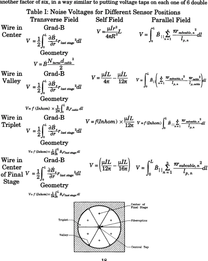
(3) Placing the cowound sensor in the part of the cable best calculated to reject transverse, longitudinal, and self-field voltages. Placement of voltage taps in the center of the final stage subcable was favored by TPX, as shown in Figure 13 {17}.
Center of Final Stage
Triplet + + Fiberoptics
Valley- + +
Central Tap
Figure 13: Placement of Sensors within Cable
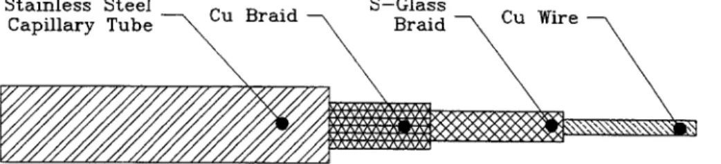
(4) Terminating the voltage sensor internally, further localizing and subdividing the winding into sections, and permitting another level of voltage differencing, such as simple differencing and central difference averaging. The two halves of the sensor form one solid wire that can be cabled and wound with the rest of the conductor. A method for forming an internal termination in a continuous sensor is shown in Figure 14. Stainless Steel Capillary Tube Copper Braid Braze Joint S-Glass Braid Copper Wire
Figure 14: Two-sided Voltage Sensor, showing internal termination between 2 halves
(5) Further signal processing, such as using integrated volt-seconds, rather than simple voltage thresholds as detection criteria.
These techniques are now described in more detail:
(1) Cowinding an insulated voltage sensor with the CICC cable.
A cowound sensor has been used previously on the US-DPC coil, where an insulated wire was wound along an edge of the conduit on the outside {21}. A cowound, insulated aluminum strip in the B&W SMES coil is also being used as structural reinforcement. If the sensor is cabled on the inside of the conduit, as shown in Figure 13, the degree of noise cancellation will improve by at least another order of magnitude. The ITER QUELL (Quench on Long Lengths) experiment demonstrated
the cabling and extraction of voltage sensors on the surface of a cable, but inside the conduit, for a 100 m length of conductor. In the QUELL experiment, the rejection of transverse voltage was more than 400 times better than that of conventional voltage taps {211. Two TPX experiments, one with a copper cable, the other with a NbTi cable, demonstrated cabling of sensors in different positions of a full-scale cables (171. Depending on the sensor position, noise rejection ranged from 600-60,000:1.
(2) Extracting voltage sensors at joints.
Joint extraction from the ends of a continuous winding, while difficult, is much less intrusive than extraction every 2 layers or pancakes through the winding pack. The joints must already be accessible for servicing and capable of accommodating helium stubs and lines and instrumentation feedthroughs. The biggest problem with extracting voltage sensors at the joints is ensuring that they will not leak helium and that they won't be subject to electrical breakdown. The approach to preventing leaks is two-fold: a) injecting a moderately-sized seal area with a mineral-filled sealant, such as Stycast, with a good thermal match to the seal metal, and b) designing the seal to be long, in compression, and mechanically redundant in terms of interrupting individual microcracks, and c) made up of a separate, weldable piece that can be thermal shock tested or cycled before installation. A simple version of this joint was demonstrated at M.I.T. that, after two cooldowns to nitrogen, was capable of holding 70 bars on one side and vacuum on the other (171.
Design against electrical breakdown is ensured by designing the CICC itself, so that there can never be 160 V across the voltage sensor. In this case, the sensor insulation will be below the Paschen minimum for helium, irrespective of uncertainties in helium pressure due to leaks or in stray transverse or longitudinal magnetic fields. Almost any large magnet will satisfy this design approach automatically. For example, a normal zone as long as 1 km with a stabilizer current density of 200 A/m2 at an average field as high as 13 T, would have a resistive voltage of only 133 V between joints. Depending on the time needed for internal current dump, the current density can be lowered slightly, if needed, in order to compensate for resistivity rising with temperature. This should seldom be necessary.
(3) Placing the cowound sensor in the part of the cable best calculated to reject transverse, longitudinal, and self-field voltages.
The surface of the cable is not the best position for "emulating" the trajectory and therefore the flux linkage of a typical strand in a cable. The best job would be done by a sensor that was cabled into a first triplet, as though it were a strand. The second best position, identified so far, is to place the sensor in the center of the final stage of the cable, which is easier to cable and not vulnerable to conduit broaching or welding. Both positions are far superior to the center of the cable or a natural cabling valley on its surface. Equations for approximating the induced noise voltage for different types of field and sensor placement were derived by Martovetsky {22} and are summarized in Table I.
(4) Terminating the voltage sensor internally, further localizing and subdividing the winding into sections, and permitting another level of voltage differencing, such as simple differencing and central difference averaging.
In TPX, the voltage sensors were terminated internally at 1/6, 1/3, 1/2, 2/3, 5/6, and 100 % of the distance through the winding pack, as shown in Fig 15. Even before using differencing techniques, this should further reduce the noise voltage by another factor of six, in a way similar to putting voltage taps on each one of 6 double
Table I: Noise Voltages
Transverse Field
Grad-B
Geometry
V=B 2Grad-B
V~ FI =r,,,dl Geometry =f
(Inhom) x 2re dlGrad-B
V = raBd G last stage 2d
Geometry
for Different Sensor Positions
Self Field
Parallel Field
V -
2 pL pIL 4- 127rWire in
Center
Wire in
Valley
Wire inTriplet
Wire in
Center
of Final
1Stage
V= f Unhom)x s , , dGrad-B
L .a B
= -a str st a ge, 2 d 'Geometry
V= f Unhom)x ir BrIastge dI Triplet- Valley-pjL 2f(Inhom) x A2 V=I f M) IifhO
li,i Vf'hmI 1= 11". V= V fL=11 tII 2 _2 V(pL pIL) L Pl !!2d fo p C1 , n + + + + -Center of Final Stage ..- Fiberoptics '-Central Tap
pancakes. Taking a simple difference between, say, the signal at 1/6 and 1/3 is frequently ineffective, since there may be a systematic gradient through the winding pack due to eddy currents being turned around by a break on one side of the winding pack, but not the other {231. However, central difference averaging, in which 1/2 the first and third sensor signal are subtracted from the middle sensor, as first proposed by Yeh et al (241, can be effective in canceling out gradients. For example, if voltages are measured across double pancakes, the threshold voltage across the first six pancakes would then be 0.5V1-2 -V3-4 + 0.5V5-6. In simulations of TPX, the degree of further cancellation using CDA was 5-20 {171. Internal termination has the additional benefit of localizing quench initiation and of following the sequence of quench propagation through a winding pack.
Superconducting Cable
Voltage
Taps
Figure 15: Six internal voltage sensors, terminated at equal distances through cable Using a sensor insulation that is compatible with inexpensive seam-welding of the steel capillary tube permits the redundant use of multiple voltage sensors in a cable. Fabrication of sensors with S-glass braid, as shown in Figure 16, was demonstrated in the QUELL experiment and the ITER CS Model Coil. Some combination of Formvar, Teflon, and/or Kapton would be used for NbTi. Teflon would probably be most desirable, because of its ability to eliminate seams at modest temperature and pressure, thus eliminating tracking. XMPI Kapton, at higher temperature and pressure, should have even higher performance.
Stainless Steel raid S-Glass Cu Wire
Capillary Tube Braid
Figure 16: Inexpensive Voltage Sensor Concept
(5) Further signal processing, such as using integrated volt-seconds, rather than simple voltage thresholds as detection criteria. This is particularly effective in screening out short disturbances, such as stick-slip, flux jumps, and plasma disruptions. In TPX simulations, an additional factor of 10-20 in signal/noise was achieved by using a volt-second window, instead of a voltage threshold {17}. Further improvements in signal/noise ratio through signal processing have been proposed through the use of carrier signals and synchronous detectors.
In summary, although there is clearly a broad range of design specific signals and signal/noise ratios, the following rules of thumb might be used for preconceptual design of a voltage noise reduction system with the goals of achieving a signal/noise level improvement of > 105 (i.e. 10 kV down to 100 mV): Split the winding pack into sections (5-10) x Place internal sensor in cable final stage (100-1000) x central
difference average (5-10) x filter, integrate, signal process (5-10) = 104-106. Two TPX noise injection experiments, one with copper, the other with NbTi cable, demonstrated transverse field noise rejections of up to 60,000 {17}. The ITER QUELL coil had both conventional and cowound voltage taps on the outside of the cable in its natural valleys. In this experiment, the voltage rejection of the cowound sensor was 80 times better than that of the noninductive winding with a voltage rejection of 6:1 or 500:1 total. Another noise-rejection method used in ITER of differencing multiple in-hand windings was calculated to achieve noise rejection ratios of 300-400. A better way to normalize the results to design for all noise sources is to show that the V/(km-T/s) are << 1 for transverse field and << 10 for parallel and self-field, corresponding to << 1 V for 1 T/s over a kilometer. Placement of the sensor in the center of the final stage or in a triplet have, so far, met this goal in all experiments.
II.B.2 Advanced Fiber Optic Temperature Sensors
Conventional temperature sensors have a number of disadvantages: they cannot be inserted inside a cable-in-conduit, don't measure cable temperature directly, and have a significant time lag. Like conventional voltage taps, they can't give coverage
to a winding without frequent penetration of the insulation system. Furthermore, thermocouples are insensitive at helium temperatures, while carbon glass resistors and RTD sensors are insensitive at quench temperatures. The use of fiber optic temperature sensors, protected by a steel capillary, as shown in Figure 17, has several advantages over conventional sensors. 1) They can be inserted directly into the helium flow channel with a very short thermal time constant, 2) they are insensitive to pulsed magnetic fields {27}, helium flow, and pressure, 3) they are very small (< 50 pm), so as many fibers as desired can be placed in a single steel can, 4) the length of a fiber between joints is practically unlimited, 50 km being a routine commercial length, and 5) they have great scientific potential in the use of signal processing to provide a complete profile of temperature and field vs. length and time.
Stainless Steel S-Glass iber Optic
Capillary Tube Braid
Figure 17: Fiber-optic sensor
Fiber-optic temperature sensing works on the principle of measuring optical path length, taking advantage of the temperature dependence of the glass index of refraction. The change in phase from either effect is:
Ap = 2[nAL +AnL] (2)
The major problem with this technique is the rejection of path length changes due to mechanical strain in the glass. One strain-rejection technique is to decouple the glass from the conduit containing it, so that they don't share strain. At M.I.T., a fiber was inserted in a 1.0 mm stainless steel capillary tube and several turns were wound on an 80 mm steel tube. The assembly was heated to 700 C, then cooled to 4
K without damage, thus demonstrating strain decoupling and the absence of a capstan multiplying effect on fiber tension {28}. The QUELL experiment
demonstrated that the relatively loose fit of a copper-clad fiber in its can reduce the strain-sharing by a factor of 10-100. However, mechanical strain was still a
dominant effect, since the changes in index of refraction are < 1 %. It has been demonstrated by Smith that the mechanical strain and temperature dependent signals can be almost totally decoupled by using two independent signals with different strain and temperature dependences {29). This can be accomplished by the use of polarization maintaining (PM) optical fiber, 2 color operation, or 2 mode operation. Each polarity, color, or mode has a different, calibrated ratio of strain and temperature dependence, so that the gain on one phase shift can be adjusted to 'tune out' the strain signal This method has the additional benefit that it can also be used to measure the integrated conductor strain. Overall system
cost-performance analysis indicates that two mode operation will probably be the most cost-effective long-term solution. Typical sensitivities are shown in Table II.
TABLE II: Sensitivity of Dual-Mode and Dual-Polarity Fiber to Temperature and Strain Method Temperature sensitivity Strain sensitivity
(radians/m-K) (radians/m-e) (radians/m-(dl1))
2 Polarities 1.2 5 x 10³
2 Modes 2.18 55 x 103
2 Colors 0.1 0.5 x 10 3
Glass-fiber must be clad in order to prevent the entrance of water during handling. Commercial acrylic fibers are adequate for NbTi, but will not survive Nb3Sn, NbAl, or BSSCO heat treatments at > 600 C. Although the surrounding steel can will
contain any spattering of the cladding, this solution is, at best, messy. Coatings of copper, gold, or graphite can protect the glass fiber and survive heat treatments. Unjacketed acrylic coatings should be used outside of the joint region, so that high-voltage cryostat feedthroughs won't be necessary.
The same design principles of internal termination applied to voltage sensors within a winding pack apply to fiber optic temperature sensors. If they are
internally terminated by sputtering mirrors on polished cuts, as shown in Figure 18, the integrated noise temperatures are reduced by the number of subdivisions, then reduced further by differencing techniques.
Stainless Steel S-Glass
Capillary Tube Braid
Gold Sputtered Fiber Optic
Mirror
Figure 18: Internal termination of Fiber Optic Temperature Sensor
Subdivision also allows greater localization of quench events. In the special case of irradiated magnets, it also helps keep the signal attenuation manageable (<60 db). The method for subdividing a fiber is to cut the fiber at the desired length, polish and silver the end. The fiber end is then a mirror and the laser light signal returns to the splitter and detector to form the information-carrying half of a Michelson interferometer.
After converting phase shifts to voltages, the same signal processing concepts used for voltage sensors can also be used for fiber optics. Integrating the number of fringe shifts over a time window, such as one second, can achieve an order of magnitude improvement in signal-noise ratio. The signal-noise ratio of the fiber optic quench detector is naturally enhanced by the increase in sensitivity with rising temperature. Simulations of quench and disturbances in TPX showed minimum signal/noise ratios of 600:1 for quench detection within a second {28}.
This was both within design criteria and superior to internal voltage sensors. The temperature sensitivity of the fibers has been measured with and without cladding
and can be characterized by an initial quadratically increasing fringe count according to the equation:
I
adT=1.75 T217.5 T +43.25; 5K<T <9K (3)The increasing sensitivity saturates at about 15 fringes/m-K, and then only increases to about 25 fringes/m-K at room temperature, as shown in Figure 19:
16 350 14- 300 12 -250 10 -200 -150 -100 2. -50 0 --- -i - I I p I 0 5 7 9 11 13 15 17 19 21 23 25 27 29
Fig 19: Temperature sensitivity of glass fibers
If the fiber optic sensor is considered to be a length-temperature rise integral
measurement, the sensitivity is 200 times higher at 30 K than at 5 K. Therefore, a global disturbance that raises the helium temperature throughout a 1 km winding from 5 to 5.2 K will give a signal that is smaller than a quench that raises 1 m of conductor to 30 K.
For an unclad fiber, the sensitivity is almost exactly one-tenth that of a clad fiber, the thermal strain of the plastic cladding acting as an "amplifier" of the
temperature signal. The curves in Figure 19 can be used for design of temperature sensors with NbTi; but fringes/m-K should be multiplied by 0.1 for design with Nb3Sn.
Fiber optic sensors would use the same sort of prefabricated and pretested seal as the voltage sensors. However, a few inches of clearance would be needed between a joint and the initial position of the seal piece, in order to use a handheld field
splicer. The optical fiber can then be coiled into the pocket of the seal piece.
II.C Quench Detection Conclusions 1) Fiber-optic temperature sensors and internal voltage sensors have been shown by simulation and experiment to improve signal/noise ratios in quench detection
systems by several orders of magnitude.
2) A leak-free method for extracting sensors has been demonstrated, and a redundant and replaceable sealing system has been designed.
3) A method for coil/sensor electrical design has been defined that is robust against arbitrary helium pressures and magnetic fields. Enormous safety margins are feasible with NbTi and fused Teflon or Kapton insulation.
4) Advanced quench detection sensors can also be used as scientific instruments, measuring the internal properties of CICC conductors.
LII. Magnet Protection Criteria
A popular and conservative protection criterion is to assume that there is no heat transfer from the local hot spot where quench is initiated and that all Joule heating is absorbed by the stabilizer. In this case, the relation between the peak allowable hot spot temperature and the J2 t integral of the conductor stabilizer during a coil dump is a unique property of the stabilizer material, usually copper. The maximum allowable current density is then determined by the peak allowable hot spot
temperature and the peak allowable terminal voltage for a coil dump. Typical values of peak temperature allowables are 80-200 K If a coil is completely
supported in compression by external structure, as an accelerator coil in a large iron yoke, it is possible to design up to 450 K or the melting point of solder {30}. A
typical allowable terminal voltage for a pool-boiling magnet is 1-3 kV, and 3-20 kV for a CICC magnet. However, as discussed in the chapter on electrical protection, the fundamental limits on voltage for both topologies are strong functions of specific
design.
Irrespective of the coil temperature allowables, the selection of the peak terminal voltage fixes the minimum IJR dump time constant (s) at:
-C 2W. (4)
where W is the stored energy in the magnet (J), V., is the peak allowable terminal voltage on dump (V), and Ic,,,d is the conductor current (A). For a system dumping it's energy into a linear external resistor with negligible resistive voltage within the coil system, the magnet current after switching is simply:
I(t) = I,0 exp RDt (5)
where Rd/Lm is the dump time constant t (s).
Since a quench will not be detected immediately, there is also a delay time before any action is taken. This has sometimes been specified as 1-2 s as a design goal, but it is a function of the signal/noise ratio of the quench detection system, as explained
in that section. The allowable current density in the copper then is fixed by the combination of delay plus dump time as:
= Z(T) (6)
where td is the maximum possible time delay (s), Tf is the final temperature at
the end of dump (K), and G(Tf) or, alternatively in some texts Z(Tf) , is a property,
unique to each material or combination of materials, defined as:
T (7)
'fC(T)
Z(T) =f c(T J dT
T p(T)
This integral can also be thought of as the J2 t integral of the current in the
conductor during a dump, and is thus usually represented with the units (A2 Im4 -s). An analytical approximation for G(Tf) for copper from a bath temperature of 4.2 K is:
Z
(T)=
13673
x 101(8)
Another way of stating the design constraint, derived by Iwasa and Sinclair {3 1} defines Z(Tf as the integral from the detection temperature to the final temperature and models the presence of materials other than substrate by a correction factor a, which is the enthalpy change ratio of substrate/all other materials, which can be
determined by table lookup or approximated as a volumetric ratio. The maximum allowable current density in the substrate is then:
(1 + a) VDIoZ(TD,TF) (9)
k a) EM
where VD is the dump voltage (V), 10 is the operating current (A), and Em is the stored energy (J).
Iwasa's "a -factor" can be quickly estimated with a curve of volumetric specific enthalpies and the volumetric ratios of the different constituent materials in a design. The specific enthalpies of copper, aluminum, iron, nickel, niobium, titanium, tin, Teflon, helium at 130 kg/m3 and helium at 150 kg/m3 are plotted from 4.5 K to 300 Kin Figure 20. 8x10⁶ 7x10- -Copper - - -Iron 5x10⁸- - 4x1--3x10 -2x10- + 1xl08 -+ H m3' 0 50 100 150 200 250 300 + Temperature (K) ----+---- Helium: 150kg/m^3
Figure 20: Specific enthalpies of magnet materials (J/m3) vs. temperature (K) Copper and nickel are the two best materials above a maximum temperature of
100-120 K. However, there is no more than a factor of two difference between the best and the worst metals. Copper is about 60 % better than aluminum; but since aluminum is 3 times lighter than copper, it is twice as good as copper, if
energy/mass is a more important consideration than energy/volume.) Copper is clearly also the best material from an adiabatic J2t criterion. Therefore, if the
design is limited by the hot spot temperature in a given volume, copper is the material of choice.
The curves of Z(Tf) vs. T (K) in Figure 21 appear in Iwasa's casebook {32}. -- 9- Nickel ---- --- Niobium ... ... Titanium - -X- - Tin - --- - Aluminum --- a---- Teflon
r-1-20 1 15j 10 5 100 300 T[K]
Figure 21: Z(Tf) functions: 1. Silver (99.99%); 2. Copper (RRR 200); 3. Copper (RRR 100); 4. Copper (RRR 50); 5. Aluminum (99.99%)
While high-purity silver has the best Z(TF), far-less expensive oxygen-free coppers are nearly as good. Copper is 2-3 times as good as high purity aluminum. The Z(TF) vs. TF(K) curves in Figure 22 were calculated specifically for a tradeoff between copper and stronger, less high purity aluminums. The curves show that
copper is 20-25 times better than aluminum alloys. The implication is that the cross-sectional area of copper needed for protection in a design where the available enthalpy is dominated by the stabilizer would be 4-5 times less than that of
aluminum. In a design in which other components, such as superconductor, helium, or other structure were important, the superiority of copper would be reduced.
Magnetoresistivity would also reduce the quantitative superiority of copper. In magnetic energy storage designs, the main factor that improves the relative position of aluminum is that an aluminum such as 2219 can also be used as a structural material. In a design that requires a structural cross-section that is several times larger than the cross-section needed for protection, the volumetric advantage of copper would disappear.
1.4E+ 1.4E+ 1.2E+ 1.DE+ BE+ BE+ 4E+ N a,. 17 IE+1 17 17 3E+16 VAf 17 16 2E+16 is 1E+16 16 0 so 100 150 200 250 300 e N 14 E 0 0 T(K)
Figure 22: Z(Tf) functions: 1) Copper (RRR=200), 2) Copper (RRR=100), 3) Copper (RRR=50), 4) Aluminum alloy (RRR=5.5), 5) Aluminum alloy 2219
The values of Z(Tf) from Figure 22 are listed in Table III.
Temperature 4 10 20 50 75 100 145 190 240 273 300
Table III: Z(Tf) functions for copper and aluminum
Copper, RRR=200 0 3.173 x 10¹⁴ 4.776 x 10¹⁵ 3.847 x 10¹⁶ 6.757 x 10¹⁶ 8.633 x 10¹⁶ 1.097 x 10¹⁷ 1.285 x 10¹⁷ 1.410 x 10¹⁷ 1.505 x 10¹⁷ 1.561 x 10¹⁷ Copper, RRR=100 0 1.597 x 10¹⁴ 2.481 x 10¹⁵ 2.798 x 10¹⁶ 5.457 x 10¹⁶ 7.274 x 10¹⁶ 9.567 x 10¹⁶ 1.142 x 10¹⁷ 1.268 x 10¹⁷ 1.360 x 10¹⁷ 1.416 x 10¹⁷ Copper, RRR=50 0 7.953 x 10¹³ 1.256 x 10¹⁵ 2.005 x 10¹⁶ 4.283 x 10¹⁶ 5.990 x 10¹⁶ 8.206 x 10¹⁶ 9.793 x 10¹⁶ 1.116 x 10¹⁷ 1.192 x 10¹⁷ 1.247 x 10¹⁷ Al Alloy (RRR=5.5) 0 2.280 x 10¹² 2.584 x 10¹³ 9.466 x 10¹⁴ 2.898 x 10¹⁵ 5.538 x 10¹⁵ 1.050 x 10¹⁶ 1.504 x 10¹⁶ 1.941 x 10¹⁶ 2.195 x 10¹⁶ 2.386 x 10¹⁶ IV. Quench Propagation
IV.A Adiabatic (potted) magnets Adiabatically cooled magnets are selected for applications that are relatively small, and quasi-steady state, since they are incapable of absorbing large amounts of local energy. They are particularly suited to applications where there can't be any cryogenic fluid within the magnet and where small, compact winding packs are required. Iwasa has argued convincingly
{35}
that most HTS magnets are also likely to adiabatically cooled, because the local energy absorption is improved by orders of magnitude at higher temperatures.Adiabatically cooled magnets may be protected either by internal or external energy dumps. If the simplifying assumption is made that the thermal conductivity and
- Copper(RER=200) Copper(RRR=100) - - A - - Copper(RRR=50) Al A1loy(RRR=5.5) --- A12219 A12219-T85 0 5.688 x 6.422 x 2.517 x 8.521 x 1.827 x 4.055 x 6.451 x 9.016 x 1.062 x 1.186 x 1011 1012 1014 1014 1015 1015 1015 1015 1016 1016 2E+
heat capacity of all materials is temperature independent, the longitudinal quench propagation velocity is expressed by the balance of constant local heating density and thermal diffusion through the winding pack as 1321:
S- Jp kn (10)
Vpropagation ~. 4(
CCS
T+
T )where vpropagation is the longitudinal quench propagation velocity in the winding direction (m/s), J is the current density in the composite wire (A/m2), pn is the
electrical resistivity of the composite wire (Q-m), kn is the thermal conductivity of the normal wire (W/m-K), Cn and Cs are the heat capacities of the wire in its normal and superconducting states respectively (J/m3-K), and TopTe and Tes are the
operating and superconductor transition temperatures respectively (K) 136. Again, because the heat capacity of all materials rises much more quickly with
temperature than resistivity does, the quench propagation velocity of HTS quenches should be much lower than that of LTS quenches and the coils will be harder to protect.
IV.B Pool-boiling magnets IV.B.1 Pressure Rise
The quench pressure rise during the quench of a pool-boiling magnet involves a design tradeoff. The maximum pressure can most easily be controlled by the setting on external pressure relief valves or rupture disks {37). The additional pressure in the magnet due to pressure drops in the vent lines and the disks or valves can be solved by the time-dependent model of Krause and Christensen (381, assuming frictional, adiabatic (Fanno) flow in the vent lines. An alternative, recommended by Powell {391 is repressurization with warm helium gas. The motive for maintaining a high pressure, discussed in the section on electrical integrity, is that it will
improve the dielectric strength of warm helium. The disadvantage is that it will increase the required thickness of the liquid helium cryostat, the pulsed eddy currents in the thicker cryostat, and the conduction losses through the cold mass supports.
IV.B.2 Quench Propagation
Under normal conditions of cooling by a pool of liquid helium, the propagation velocity should obey the proportionality {401:
v, = a (j - j) (11)
where jr is the current density at which the conductor would recover (A/m2), and
jo
is the operating current density (A/m2). If the quench condition causes local dry
out, then the propagation velocity is simply 141}:
v, = a j, (12)
IV.C CICC Magnets Quench propagation in CICC conductors is usually treated as a one-dimensional problem, quench propagating from an interior normal zone toward the inlet and