A Compact Acoustic Communication
Module for Remote Control Underwater
The MIT Faculty has made this article openly available.
Please share
how this access benefits you. Your story matters.
Citation
DelPreto, Joseph et al. “A Compact Acoustic Communication
Module for Remote Control Underwater.” Proceedings of the 10th
International Conference on Underwater Networks & Systems
(WUWNET ’15), October 22-24 2015, Washington, D.C., USA,
Association for Computing Machinery (ACM), October 2015 © 2015
Association for Computing Machinery (ACM)
As Published
http://dx.doi.org/10.1145/2831296.2831337
Publisher
Association for Computing Machinery (ACM)
Version
Author's final manuscript
Citable link
http://hdl.handle.net/1721.1/111983
Terms of Use
Creative Commons Attribution-Noncommercial-Share Alike
A Compact Acoustic Communication Module
for Remote Control Underwater
Joseph DelPreto, Robert Katzschmann, Robert MacCurdy, Daniela Rus
MIT CSAIL
32 Vassar Street
Cambridge, MA 02139
{delpreto,rkk,maccurdy,rus}@csail.mit.edu
ABSTRACT
This paper describes an end-to-end compact acoustic com-munication system designed for easy integration into re-motely controlled underwater operations. The system sup-ports up to 2048 commands that are encoded as 16 bit words. We present the design, hardware, and supporting algorithms for this system. A pulse-based FSK modulation scheme is presented, along with a method of demodulation requiring minimal processing power that leverages the Goertzel algo-rithm and dynamic peak detection. We packaged the system together with an intuitive user interface for remotely control-ling an autonomous underwater vehicle. We evaluated this system in the pool and in the open ocean. We present the communication data collected during experiments using the system to control an underwater robot.
Categories and Subject Descriptors
C.3 [Special-Purpose and Application Based Systems]: Real-time and embedded systems; C.2.4 [Computer Com-munications Networks]: Distributed Systems
General Terms
Acoustic Communication, Theory, Algorithms, Design, Ex-perimentation
Keywords
underwater acoustic communication, underwater low- band-width robot control, system integration, Goertzel algorithm, microcontroller
1. INTRODUCTION
We wish to develop intuitive systems that can be used to control underwater operations. Such systems may be em-ployed by a human diver to send commands to an under-water robot, changing its mission in real time. The system may also be used to configure underwater sensor networks, Permission to make digital or hard copies of all or part of this work for personal or classroom use is granted without fee provided that copies are not made or distributed for profit or commercial advantage and that copies bear this notice and the full citation on the first page. Copyrights for components of this work owned by others than ACM must be honored. Abstracting with credit is permitted. To copy otherwise, or republish, to post on servers or to redistribute to lists, requires prior specific permission and/or a fee. Request permissions from [email protected].
WUWNet ’15, October 22-24 2015, Washington DC, USA Copyright 2015 ACM 978-1-4503-4036-6/15/10 ...$15.00.
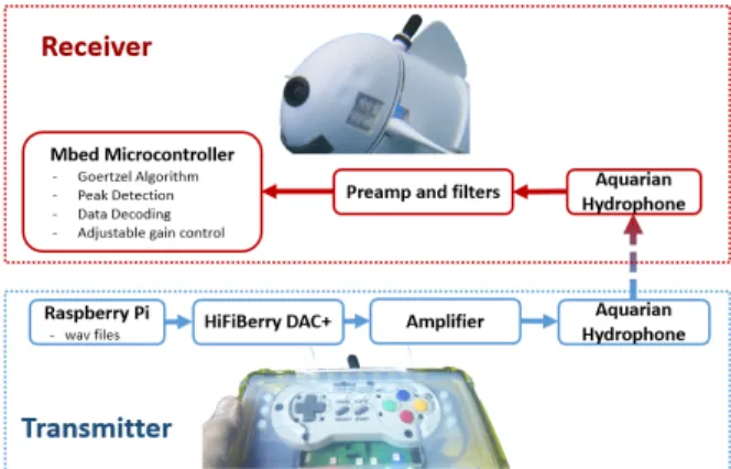
Figure 1: The system consists of a modular trans-mitter and receiver which are compact enough to be easily incorporated into various applications. Mod-ulation and demodMod-ulation are software defined for increased flexibility, and small hardware allows the modem to fit in, for example, a small robot fish. The individual components of the transmitter and receiver are based on commercially available embed-ded platforms and integrated circuits.
underwater communications systems, or to support under-water communication between people. Motivated primarily by the need to control the navigation of a small underwa-ter robot in a complex environment consisting of corals and rocks, we developed a compact, low-power module that gives a human user the capability to observe an underwater scene and issue real-time navigation commands to the robot such as “swim forward”, “turn left”, or “ascend”. Since remote robot navigation can be achieved with a limited command vocabulary, we developed a custom system that is architec-turally lean and supports a vocabulary of up to 2048 16-bit commands (including Hamming encoding). Several appli-cation challenges informed the design. First, the receiver and transmitter need to be small and compact. On the transmitter side, we envision a human carrying the system and issuing commands using fingers. On the receiver side, we envision integrating this system within small underwa-ter robots and sensors. Second, the receiver and demodula-tion algorithms must be robust in the presence of significant broad-spectrum noise since in general underwater robots and sensors have compact packaging that may place the receiver near loud motors and servos. Finally, the communication http://dx.doi.org/10.1145/2831296.2831337
system should be low cost, low power, and easy to use. As underwater robotics and sensor networks become more prevalent, there is an increasing need for such small, low cost, easily deployable underwater communication systems. Various solutions have been developed based on radio fre-quencies (RF), optical links, and acoustic signals, but they are often bulky, expensive, or computationally intensive. While many of these systems are designed for long range and/or high bandwidth general communications, applica-tions such as remotely controlling underwater robots within visible range can be satisfied with slower data rates and shorter ranges. The work described in this paper focuses on implementing a compact, low cost, low power, architec-turally lean, and easy to use acoustic transmitter and re-ceiver with minimal custom hardware.
The end-to-end acoustic communication system consists of a modular transmitter packaged in a user interface and a modular receiver that can be integrated in an underwater as-set such as a robot. The transmitter consists of a Raspberry Pi and a commercially available DAC for audio output, while the receiver consists of a preamplification and filtering board connected to an Mbed microcontroller. A pulse-based FSK modulation scheme is presented, along with a method of de-modulation requiring minimal processing power that lever-ages the Goertzel algorithm and dynamic peak detection. The user interface consists of a game controller packaged in a 22 cm x 22 cm x 8 cm water-tight enclosure.
We have evaluated the underwater remote control sys-tem in the pool and in the ocean. These experiments were a first step towards characterizing its communication pa-rameters and using the system to control a small robot: a bio-inspired robotic fish measuring approximately 47 cm x 24 cm x 18.5 cm with only 30 cm3available for the acoustic receiver. The remote control unit successfully steered the robot during 6, 45-minute trials in a complex underwater environment. The remote control system supports 2048 dis-tinct messages with a data rate of one message per second (at 20 bits/s) using signals of 30 kHz and 36 kHz. The sys-tem can communicate over a distance of up to 10 m in a shallow, cluttered underwater environment in the presence of loud motor noise.
This paper contributes the following:
• an end-to-end unidirectional acoustic communication system whose modulation is software defined and whose only custom electronics are filtering and amplification circuits
• an acoustic transmitter module packaged with an intu-itive user interface that can be carried and operated by an underwater operator
• a receiver module that can be integrated with an un-derwater asset such as a robot and that uses a single Mbed microcontroller for sampling, signal processing, demodulation, and robot control
• a modulation scheme based on Frequency Shift Keying (FSK), and algorithms for efficiently demodulating the transmitted words
• experimental results with the remote control of robot fish in a complex coral reef environment in the ocean This paper discusses related work in Section 2, and our approach to modulation and encoding in Section 3. Section 4 describes the software and hardware of the transmitter and the receiver. Results from experiments in a fish tank, a pool, and the open ocean are then presented in Section 5, and Section 6 concludes and indicates future work.
2. RELATED WORK
One avenue that has been explored for underwater com-munication is to use RF signals [16]. However, radio-frequency signals are rapidly attenuated in saltwater, severely restrict-ing the feasible transmission range [7]. Optical communi-cations are a common alternative choice for aquatic data transmission, and works such as [22, 10, 11] have used optical systems to transmit data. However, visible light is subject to significant scattering, and ambient light near the surface can introduce noise in the communication channel. In addi-tion, optical links are typically directional and may require steering apparatus or arrays of transmitters and receivers in order to achieve omni-directional communication.
Considering the difficulty of communicating underwater via electromagnetic waves, acoustic transmission has been widely adopted [8, 20]. Yet the underwater environment also presents challenges for acoustic methods [2], such as multipath e↵ects and Doppler shifts. A modem developed at the Woods Hole Oceanographic Institution [14, 12] is able to operate in this difficult environment, but the physical size and the power consumption are too large for the com-pact underwater devices targeted in this paper. Similarly, many other modems such as those described in [17, 19] and commercially available modems such as [4, 15] are gener-ally focused on higher data rates and longer ranges than are required for remote underwater operation by a diver, and become too bulky and expensive for the presented ap-plication. Additionally, many acoustic modems such as [22] use hardware-defined signal generation and detection, which limits the available processing and reduces versatility.
Compared to existing systems, we desired a module that does not require elaborate synchronization between trans-mitter and receiver and that uses a lean communication pro-tocol. Most of the previous works are designed to send large chunks of arbitrary data, but become inefficient for sending small amounts of data at a time as an underwater control application requires. We wanted a modular plug and play system for sending words from a limited vocabulary, that could be easily integrated into an existing compact under-water robot and that facilitates the easy implementation of various encoding schemes.
3. MODULATION AND ENCODING
Figure 1 summarizes the architecture of the acoustic com-munication module for underwater remote control. It il-lustrates an encapsulated controller as transmitter and a robotic fish as receiver, but the system is modular and can be integrated in any underwater system. This section de-scribes the underlying approach to encoding bits and words, addresses the problems of multipath and frequency shifting, and provides an explanation for the chosen communication frequencies. The implementation of these concepts is then given in Section 4.
3.1 Encoding of Bits
We implemented a modulation scheme that can be ef-ficiently demodulated by a microcontroller while still ad-dressing acoustic challenges such as multipath and Doppler shift. The scheme is based on Binary Frequency Shift Key-ing (BFSK), where two frequencies are chosen to each rep-resent a binary 1 and 0. Rather than continuously playing either of these tones, however, our protocol represents a bit
Figure 2: A bit is represented by a brief pulse of one of two frequencies, followed by a period of silence to wait out multipath e↵ects such as reflections. The receiver only needs to detect leading edges of pulses. as a brief pulse of the appropriate tone followed by a pe-riod of silence as illustrated in Figure 2. An advantage of this modulation is that it can be reliably demodulated by a microcontroller without requiring specialized circuitry or intensive processing. Furthermore, it does not require elab-orate methods of establishing synchronization or alignment between the transmitter and the receiver.
3.1.1 Frequency Choice
The sampling rate of the microcontroller was set to 250 kHz, so the frequency content of our signals must be below 125 kHz. The tone detector’s parameters yield an e↵ective bandwidth of 2 kHz, so the frequencies used for FSK modulation should preferably be separated by twice this amount to prevent cross contamination between channels.
We also considered ambient noise in the ocean as a source of interference with the receiver. Man-made sources and seismic activity add broad spectrum noise to the ocean, though frequency-dependent attenuation limits the likely level of interference from distant sources to frequencies less than 10 kHz. Noise from wind and waves can be considerable between 10 kHz and 100 kHz [20] and is more significant in shallow water [21, 6]. Additionally, noise from fish is typi-cally below 10 kHz [5]. Finally, it has been observed that the hearing sensitivity of many common aquatic species decays significantly above 10 kHz [3, 18] although some cetaceans and pinnipeds can hear well above this range [1].
Taking these considerations into account, the current im-plementation employs a tone of f0 = 36 kHz to represent the binary symbol 0 and a tone of f1 = 30 kHz to represent the binary symbol 1.
3.1.2 Multipath and Reflections: Pulse Timing
Our scheme addresses reflections via the guard intervals between pulses, which are chosen to be long enough to out-last dominant reflections. The receiver only needs to detect leading edges of tone pulses; as soon as it identifies a pulse, it enters a waiting (guard) state and ignores incoming signals. We observed that most reflections die o↵ after approximately 20 ms when testing in a fish tank and after approximately 3 ms in a large pool (see Figure 3). The current implementa-tion sets a very conservative tguard = 45 ms. The duration of the pulse must be long enough to ensure reliable detec-tion at the receiver, and the current implementadetec-tion setstpulse = 5 ms.
3.1.3 Frequency Shifts
Another challenge of underwater communications is fre-quency shifting. A common cause of this is the Doppler
e↵ect, which can be significant when considering the rela-tively slow speed of sound in water [9]. In addition, clock drift in the microcontrollers may cause discrepancies in the received frequency content. Our modulation scheme there-fore includes a tone detector bandwidth, currently 2 kHz, wide enough to accommodate Doppler shifts and oscillator uncertainty.
3.2 Encoding of Words
Data words are encoded by sequentially transmitting bits followed by a waiting period. This waiting duration is lower-bounded by the bit-level guard interval. The current imple-mentation conservatively uses at least twice tguardto ensure the reliable detection of the start of a word.
The target application requires the transmitter to control four parameters: thrust, frequency, pitch, and yaw. Thrust and frequency are each defined to have 4 states, while pitch and yaw are each defined to have 7 states, so the entire fish state can be represented by 10 bits. An additional bit is included to toggle video recording. These 11 bits are ex-panded into a 16-bit word via a (15, 11) Hamming encoding with an additional parity bit.
4. IMPLEMENTATION
Our modulation protocol was implemented as a small and low cost platform suitable for integration into a compact robot fish. Figure 1 shows a block diagram of the system.
4.1 Transmitter
4.1.1 Hardware
The main hardware components of the transmitter are a Raspberry Pi Model B+ with a HiFiBerry DAC+, a PCB containing an audio amplifier and output transformer, indi-cator LEDs, an unamplified hydrophone, and a USB game controller. These were packaged into a waterproof OtterBox modified to have a flexible rubber membrane that allows button presses. The box was then filled with mineral oil to provide pressure equalization across the membrane.
4.1.2 Software
In order to maintain versatility, a wav file was precom-puted according to our modulation scheme for every possi-ble data word. The stereo wav files’ Left and Right chan-nels are inverted relative to each other to form a di↵erential drive signal for a mono amplifier, and use 16-bit sampling at 192 kHz. As the user uses the game pad, the desired state of the robot is updated on the transmitter and indicated via LEDs, and the appropriate wav file is selected. Since com-munications are one-directional, no acknowledgments from the AUV are possible; the current state is repeatedly played once per second so that if a transmission is corrupted, the robot will eventually receive the desired state.
4.2 Receiver
4.2.1 Hardware
The receiver is implemented using an Mbed microcon-troller based on the NXP LPC1768 with a 32-bit ARM Cortex-M3 core running at 96 MHz. The on-board 12-bit ADC is used to sample the audio signals coming from a hy-drophone via a PCB containing filtering and pre-amplification circuits. Space and mass limitations restricted the hydrophone
choice to small unamplified piezoelectric types. The model we selected (AS-1 from Aquarian Audio) has a typical voltage-mode receive sensitivity of -207 db re 1 V/µPa. The hydrophone has a transmit sensitivity of 116 dB re 1 V/µPa (1 Vrms in-put at 1 m range) at 30 kHz and can be driven at up to 70 V peak-to-peak, yielding a transmit sound pressure level of 143 dB re 1V/µPa. A spherical spreading model predicts that the received signal level at 10 m range will be 70 µV RMS, requiring 80 dB of gain to saturate the ADC. We designed a multi-stage amplification board that employs a low-noise JFET common-source amplifier to bu↵er the hy-drophone and provide 17 db of gain. The signal is then bandpass-filtered and amplified by 40 db using a Quad Op Amp circuit in a Sallen-Key topology. The pass band is 20 kHz wide, centered at 30 kHz, and employs a Bessel re-sponse to provide uniform group delay. Finally, the sig-nal passes through a variable gain amplifier (VGA), capa-ble of controlling the gain from 0 to 40 db, in 7 increments distributed linearly-in-db. Audio signals often span many decades of intensity and the VGA stage allows the detector to ensure that the limited dynamic range of the 12 bit ADC is matched to the strength of the received signal. The en-tire receiver consumes approximately 815 mW during normal operation (with the microcontroller using about 740 mW of that power).
The small microcontroller and limited custom hardware enable installation within a compact underwater device. For example, it was integrated into a robotic fish that only has 30 cm3available for the acoustic receiver.
4.2.2 Sampling
The Mbed’s onboard ADC is configured to be triggered by a hardware timer every 4 µs. A Direct Memory Access (DMA) chain then fills a bu↵er with these samples, allowing fast sampling to be achieved without consuming processor time; signal processing and demodulation can occur while the next bu↵er of samples is being acquired by the hardware. Note that this implies the demodulation algorithm must be fast enough to terminate in less time than it takes to acquire a bu↵er of samples.
4.2.3 Tone Detection and Adaptive Peak Detection
Although performing a Fast Fourier Transform (FFT) on the bu↵ers of samples proved too computationally inten-sive for the embedded application, individual terms of the Discrete Fourier Transform (DFT) can be computed using the Goertzel Algorithm [13], which was implemented on the Mbed using fixed-point arithmetic. The e↵ective bin width of the Goertzel algorithm is defined by the sampling inter-val and the bu↵er size; the current sampling frequency is 250 kHz and each bu↵er consists of 125 samples, yielding an e↵ective bandwidth of 2 kHz. The computed tone powers are low-pass filtered and passed to an adaptive peak detec-tion algorithm, which maintains a circular bu↵er of the last 25 ms worth of results (half of a bit width using the current timing). As each new result arrives, the bu↵er is evaluated to determine whether or not a tone has been detected; it im-poses some a priori knowledge about the anticipated shape of a peak, and uses the other frequency channel as an esti-mate of noise level since only one tone should ever be present at a time. The structure of a peak is imposed by concep-tually dividing the bu↵er into a smaller region of the most recent outputs, bsmall, and the remaining larger portion ofolder outputs, blarge. The following are then tested: • bsmall> blarge⇥ 0.625
• max bsmall> max blarge
• bsmall> bsmall other channel⇥ 1.14 • bsmall> blarge other channel⇥ 0.625 • max bsmall> blarge⇥ 0.0625 • max bsmall> 100
If at least 6 positive detection decisions are made within a period of 10 samples, a tone is declared present. For com-putational efficiency, summations are stored rather than av-erages and the constant factors above were chosen so that all calculations can be achieved using bit shifts rather than explicit multiplication or division.
Using these optimizations, the algorithm completes within the time it takes for a bu↵er of samples to be gathered. All processing of a bu↵er, including Goertzel filtering, peak detection, demodulation, and adjustable gain control, com-pletes in under 120 µs (40% of the bu↵er acquisition time). This adaptive peak detection algorithm, combined with the inherit ability of the Goertzel algorithm to accentuate values for the desired tones, allows the receiver to be robust to noise as well as rapidly varying signal levels that occur as the hydrophones are displaced relative to each other and the underwater channel characteristics change.
Algorithm 1 Outline of Bit and Word Detection Algorithm
1: timer 0 . Counts sample bu↵ers
2: bitIndex 0 . Index into current data word
3: betweenW ords false . Whether we think we are in the
inter-word guard interval 4: while Receiver Running do
5: Acquire bu↵er of samples . Using DMA
6: timer timer+1
7: Apply adaptive thresholding to tone detector outputs 8: if tone is detected then
9: if timer > interWordWait then . Check for inter-word guard interval
10: if betweenWords and have complete word then
11: . Successfully received word
12: Decode Hamming word and command fish
13: bitIndex 0
14: else if¬betweenWords then . A bit was omitted
15: bitIndex 0
16: end if
17: betweenW ords false
18: else if betweenWords then . A bit was inserted
19: bitIndex 0
20: end if
21: if¬betweenWords then . Store the new bit
22: Add new bit to current word at indexbitIndex
23: bitIndex bitIndex+1
24: timer 0
25: if have complete word then
26: betweenW ords true . Command will be
applied at start of next word to protect against bit insertions
27: end if
28: end if
29: Set flag to wait for inter-bit guard period
30: end if
31:end while
4.2.4 Word Detection
The timing of the modulation protocol forms the basis of a state machine, outlined in Algorithm 1, that gathers bits into complete words of data. This timing is also used to de-tect erroneous bit insertions and deletions, while the Ham-ming code is used to detect erroneous bit flips. Although synchronization may be lost due to erroneous bit insertions
Time (ms) 10 20 30 40 Transmitted Signal (V) -1 -0.5 0 0.5
1 Reflections in Fish Tank
Time (ms) 10 20 30 40 Recevied Signal (V) 0.5 1 1.5 2 2.5 Time (ms) 2 4 6 Transmitted Signal (V) -20 -10 0 10 20 Reflections in Pool Time (ms) 2 4 6 Recevied Signal (V) -0.1 -0.05 0 0.05 0.1
Figure 3: Signals received when transmitting brief pulses in a fish tank (left) and in a big pool (right) clearly demonstrate the presence of reflec-tions. Since longer paths lead to higher attenuation, the signal-to-noise ratio of multipath e↵ects dies o↵ after about 25 ms in the tank and 3 ms in the pool. or deletions, the state machine will detect this at the comple-tion of a word and automatically reestablish synchronizacomple-tion at the start of the next word.
4.2.5 Adjustable Gain Control
In order to account for varying signal levels, the preampli-fier o↵ers 7 levels of programmable gain. As each bu↵er of samples is gathered, the Mbed records the average value of the raw incoming signal (computed using a bit shift rather than explicit division) and sums them over a 10 second pe-riod. Knowing the current gain being applied to the sig-nal, the ideal new gain to keep the received signal at about 2 Volts Peak-to-Peak can be calculated. From the available gains of 1, 2, 5, 10, 20, 50, and 100, the best setting is then chosen and applied.
5. EXPERIMENTAL RESULTS
We evaluated this system in a fish tank, a pool, and in the ocean to evaluate its reliability, speed, range, and ro-bustness. We present data collected from experiments where the acoustic communications were isolated and from experi-ments where the system was used to control an autonomous underwater robotic fish.
5.1 Pool and Tank Experiments
The communication system was evaluated in a fish tank (1.2 m x 0.3 m x 0.45 m), a small pool (12.5 m x 5.5 m x 1.2 m) and a big pool (23 m x 12.5 m x 3 m), whose confined natures lead to interfering reflections. Although signal paths in the pool have longer times of flight, highly delayed reflections will be significantly attenuated. As can be seen in Figure 3, e↵ects from reflections die out quickly in the pool but are more sustained in the fish tank.
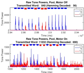
The performance of the system in the presence of noise was also investigated by running the robot’s motor, which injects significant broad-spectrum noise as illustrated in Figure 4. The strong impact of this on the outputs of the Goertzel algorithm can be seen in Figure 6 and Figure 7. The adap-tive peak detection algorithm is still able to recover the data from the received signal over a diminished range.
Figure 4: The motor of the robot fish introduces significant noise across a wide range of frequencies, as seen in this Fast Fourier Transform recorded from a hydrophone nearby the motor in the small pool.
Distance Between Transmitter and Receiver (m)
0 5 10 15 20 25
Percent Received
60 80 100
Percent of Data Received
0.2 m depth, motor off 1.8 m depth, motor off 1.8 m depth, motor on
Distance Between Transmitter and Receiver (m)
0 5 10 15 20 25 Number of Bits 50
100 150 200
Longest Error-Free Segment Received Out of 200 Bits
0.2 m depth, motor off 1.8 m depth, motor off 1.8 m depth, motor on
Figure 5: A sequence of 200 alternating bits was transmitted over varying distances in a big pool, with the motor on and o↵, to evaluate range and robustness. The results indicate e↵ective communi-cation at ranges of about 15 to 20 m.
We investigated the system’s ability to cope with these challenges by transmitting a sequence of 200 alternating bits at a rate of 20 bits/second. The entire sequence was suc-cessfully received without any errors in the fish tank at a distance of 0.5 m with the motor turned o↵. Results from performing the experiment in the pool at various distances and depths, both with the motor o↵ and on, are presented in Figure 5. With the receiver very close to the surface, error-free communication was observed at a 6 m range and about 70% of the data was received at a range over 10 m. When the receiver was submerged to a few meters, error-free com-munication was observed for ranges up to about 15 m, with over 97% of the data being successfully received at 21 m. Shallower communications are more challenging due to the increased strength of surface reflections as well as noise such as waves and swimmers. The e↵ective communication range remains similar when the robot’s motor is turned on, indi-cating the receiver’s ability to cope with additional noise. However, more trials would be necessary to make a statisti-cally significant comparison between the performance with and without motor noise.
The results indicate that e↵ective control can be estab-lished at 20 bits/second over about 15 to 20 m (and possibly longer with additional error correction logic). To demon-strate this, 16 bit data words were transmitted with 50 ms for each bit and 200 ms between words. At separations of about 0.5 m in the fish tank and 10 m in the small pool, a 250 word sequence was successfully received without any
er-Time (ms) ×104 1.17 1.18 1.19 1.2 1.21 1.22 1.23 1.24 1.25 1.26 Tone Power ×104 0 1 2
Raw Tone Powers, Fish Tank, Motor On Transmitted Word: 35768 (Hamming Decoded: 182)
f 0 f 1 Time (ms) 6100 6200 6300 6400 6500 6600 6700 6800 6900 7000 Tone Power ×104 0 1 2
Raw Tone Powers, Fish Tank, Motor Off Transmitted Word: 35768 (Hamming Decoded: 182)
f0 f1
Figure 6: Outputs of the Goertzel algorithm are plotted for experiments in the fish tank, and the dots above the signals indicate bit detections as de-termined by the peak detection algorithm. The out-puts are very consistent without the motor on, al-though significant distortion occurs in the presence of motor noise (bottom) due to the highly rever-berant environment. The data word is successfully detected in both cases.
rors. Examples of Goertzel algorithm outputs can be seen in Figure 6 and Figure 7, where the experiment was performed in the tank and in the pool, respectively. The figures also indicate decisions of the adaptive peak detector to illustrate the demodulation. Peaks observed in the fish tank are very consistent, while peaks observed in the pool exhibit fluctu-ations due to the water’s motion and to the drifting motion of the hydrophones. The significant interference caused by motor noise is also apparent in the figures via the distortion and attenuation observed with the motor on. Nevertheless, the peak detection algorithm is able to successfully identify the received bits and words in all cases.
5.2 Ocean Experiments: Robot Integration
Our system was used in an open ocean environment to remotely control a robotic fish. The desired fish state, en-coded as a 16 bit word, was transmitted from the controller once per second using a bit rate of 20 bits/second. Oper-ating the fish for over four hours throughout the course of three days, divers using this controller were able to success-fully steer the robot in a complex underwater environment and observe marine life. E↵ective communication was es-tablished with the robot over a range of within 10 m when the robot’s motor was o↵ and within 5 m when the motor was on. These tests demonstrate the ability of the system to provide real time remote control of underwater systems in a real deployment environment.6. CONCLUSIONS AND FUTURE WORK
An acoustic communication modem suitable for easy in-tegration into a remotely controlled underwater robot has been described. All signal processing and data detection is performed using commercially available embedded devices,Time (ms) 1000 1200 1400 1600 1800 2000 Tone Power 0 500 1000 1500
Raw Tone Powers, Pool, Motor On Transmitted Word: 11032 (Hamming Decoded: 690)
f 0 f1 Time (ms) ×104 2.84 2.86 2.88 2.9 2.92 2.94 Tone Power 0 2000 4000
Raw Tone Powers, Pool, Motor Off Transmitted Word: 840 (Hamming Decoded: 56)
f 0 f
1
Figure 7: Outputs of the Goertzel algorithm are plotted for experiments in the small pool, and the dots above the signals indicate bit detections as de-termined by the peak detection algorithm. Varying attenuation is observed without the motor on as the hydrophones drift through varying regions of inter-ference. Introducing motor noise (bottom) causes distortion, but the data is still recovered in both cases.
making it both compact and low-cost. In addition, the mod-ulation and demodmod-ulation are both defined in software, mak-ing it versatile and facilitatmak-ing alternate protocols.
The communication system was tested by itself both in a fish tank and in a pool, where multipath issues are sub-stantial. Additionally, it was integrated into a robot fish and deployed in an ocean environment. Despite the limited processing power available at the receiver, the fish was suc-cessfully controlled over a few meters even in the presence of motor noise.
In the future, the Raspberry Pi of the transmitter could be replaced with a smaller microcontroller such as an Mbed to reduce transmitter complexity and size. Furthermore, we will aim to increase the data rate as well as the oper-able range of the modem. A conservative data rate was chosen based on the design requirements, but it can likely be increased by merely adjusting the protocol timing. Fur-ther data rate increases may also be gained by adjusting the tone detector frequency bin size to be more selective or by tuning the peak detection algorithm. Di↵erent modulation protocols can be implemented on the microcontroller to in-vestigate their ability to operate in the presence of noise and varying signal channels. Finally, the modulation scheme can be extended to facilitate controlling multiple devices simul-taneously.
7. ACKNOWLEDGMENTS
This work was funded in part by NSF 1117178, NSF IIS1226883, and NSF Graduate Research Fellowship 1122374. We are grateful for this support. The authors declare no competing financial interests.
8. REFERENCES
[1] Bureau of ocean energy management, gulf of mexico ocs region, atlantic ocs proposed geological and geophysical activities, final programmatic
environmental impact statement. Technical Report Vol 3, Appendix H, U.S. Department of Interior, 2014. [2] I. F. Akyildiz, D. Pompili, and T. Melodia.
Underwater acoustic sensor networks: research challenges. Ad hoc networks, 3(3):257–279, 2005. [3] M. L. L. Amundsen. Marine seismic sources part viii:
Fish hear a great deal. GEO ExPro, 8(3):42–46, April 2011.
[4] Benthos. www.teledynebenthos.com/product_ dashboard/acoustic_modems, 2015. [Online; accessed 20-Sept-2015].
[5] D. H. Cato. Marine biological choruses observed in tropical waters near Australia. The Journal of the Acoustical Society of America, 64(3):736–743, 1978. [6] D. H. Cato. Features of ambient noise in shallow
water. Shallow water acoustics, pages 385–390, 1997. [7] X. Che, I. Wells, G. Dickers, P. Kear, and X. Gong.
Re-evaluation of RF electromagnetic communication in underwater sensor networks. Communications Magazine, IEEE, 48(12):143–151, 2010.
[8] M. Chitre, S. Shahabudeen, and M. Stojanovic. Underwater Acoustic Communications and
Networking: Recent Advances and Future Challenges. Marine Technology Society Journal, 42(1):103–116, 2008.
[9] R. Diamant, A. Feuer, and L. Lampe. Choosing the right signal: Doppler shift estimation for underwater acoustic signals. In Proceedings of the Seventh ACM International Conference on Underwater Networks and Systems, WUWNet ’12, pages 27:1–27:8, New York, NY, USA, 2012. ACM.
[10] M. Doniec, M. Angermann, and D. Rus. An End-to-End Signal Strength Model for Underwater Optical Communications. Oceanic Engineering, IEEE Journal of, 38(4):743–757, Oct. 2013.
[11] M. Doniec, I. Topor, M. Chitre, and D. Rus. Autonomous, Localization-Free Underwater Data Muling Using Acoustic and Optical Communication. In Experimental Robotics, pages 841–857. Springer, 2013.
[12] L. Freitag, M. Johnson, M. Grund, S. Singh, and J. Preisig. Integrated acoustic communication and
navigation for multiple UUVs. In OCEANS, 2001. MTS/IEEE Conference and Exhibition, volume 4, pages 2065–2070. IEEE, 2001.
[13] G. Goertzel. An Algorithm for the Evaluation of Finite Trigonometric Series. The American Mathematical Monthly, 65(1):pp. 34–35, 1958. [14] M. Johnson, D. Herold, and J. Catipovic. The design
and performance of a compact underwater acoustic network node. In OCEANS’94.’Oceans Engineering for Today’s Technology and Tomorrow’s
Preservation.’Proceedings, volume 3, pages III—-467. IEEE, 1994.
[15] LinkQuest. www.link-quest.com/html/models1, 2015. [Online; accessed 20-Sept-2015].
[16] L. Liu, S. Zhou, and J.-h. Cui. Prospects and problems of wireless communication for underwater sensor networks. Wireless Communications and Mobile Computing, 8(8):977–994, 2008.
[17] M. S. Martins, N. Pinto, G. Rocha, J. Cabral, and S. Laceros Mendez. Development of a 1 Mbps low power acoustic modem for underwater
communications. In Ultrasonics Symposium (IUS), 2014 IEEE International, pages 2482–2485. IEEE, 2014.
[18] A. N. Popper, D. T. T. Plachta, D. A. Mann, and D. Higgs. Response of clupeid fish to ultrasound: a review. ICES Journal of Marine Science: Journal du Conseil, 61(7):1057–1061, 2004.
[19] A. S´anchez, S. Blanc, P. Yuste, A. Perles, J. J. Serrano, I. Itaca, U. P. D. Val`encia, and C. D. Vera. An ultra-low power and flexible acoustic modem design to develop energy-efficient underwater sensor networks. Sensors, 12(6):6837–6856, 2012.
[20] M. Stojanovic and J. Preisig. Underwater acoustic communication channels: Propagation models and statistical characterization. Communications Magazine, IEEE, 47(1):84–89, 2009.
[21] E. J. Tucholski and S. Traffic. Underwater Acoustics and Sonar. SP411 Handouts and Notes. Fall 2006. In Physics Department, US Naval Academy, volume 12, pages 11–1 to 11–8. 2006.
[22] I. Vasilescu, K. Kotay, D. Rus, M. Dunbabin, and P. Corke. Data collection, storage, and retrieval with an underwater sensor network. In Proceedings of the 3rd international conference on Embedded networked sensor systems, pages 154–165. ACM, 2005.