Publisher’s version / Version de l'éditeur:
Vous avez des questions? Nous pouvons vous aider. Pour communiquer directement avec un auteur, consultez la
première page de la revue dans laquelle son article a été publié afin de trouver ses coordonnées. Si vous n’arrivez pas à les repérer, communiquez avec nous à PublicationsArchive-ArchivesPublications@nrc-cnrc.gc.ca.
Questions? Contact the NRC Publications Archive team at
PublicationsArchive-ArchivesPublications@nrc-cnrc.gc.ca. If you wish to email the authors directly, please see the first page of the publication for their contact information.
https://publications-cnrc.canada.ca/fra/droits
L’accès à ce site Web et l’utilisation de son contenu sont assujettis aux conditions présentées dans le site LISEZ CES CONDITIONS ATTENTIVEMENT AVANT D’UTILISER CE SITE WEB.
Internal Report (National Research Council of Canada. Division of Building
Research), 1967-07-01
READ THESE TERMS AND CONDITIONS CAREFULLY BEFORE USING THIS WEBSITE.
https://nrc-publications.canada.ca/eng/copyright
NRC Publications Archive Record / Notice des Archives des publications du CNRC :
https://nrc-publications.canada.ca/eng/view/object/?id=aa20a241-25fd-4ad8-8b83-96440c14332f https://publications-cnrc.canada.ca/fra/voir/objet/?id=aa20a241-25fd-4ad8-8b83-96440c14332f
Archives des publications du CNRC
For the publisher’s version, please access the DOI link below./ Pour consulter la version de l’éditeur, utilisez le lien DOI ci-dessous.
https://doi.org/10.4224/20338194
Access and use of this website and the material on it are subject to the Terms and Conditions set forth at
Swelling characteristics of two clays from Western Canada
Matyas, E. L.
NATIONAL RESEARCH COUNCIL OF CANADA DIVISION OF BUILDING RESEARCH
SWELLING CHARACTERISTICS OF TWO CLAYS FROM WESTERN CANADA
by
ANI\[ YZED E. L. Matyas
Internal Report No. 347
of the
Division of Building Research
OTTAWA July 1967
Certain types of natural clay soils, when wetted or
unloaded, exert large swelling forces that rnust be considered
in Illany design pr oblem s , During a summ e r te rrn as a
visiting professor, Dr. E. L. Matyas of the University of
Waterloo investigated the swelling rn e chanisrn and studied
the swelling characteristics of two well. known rna te r ia.l s fr om Western Canada. Bearpaw shale and Winnipeg clay.
This study includes a review of present concepts of the swelling m e chani sm in fine-grained soils and the rn ea s ur
a-m ent of swelling pressures by various techniques. The test
rn e thod s are appraised and the significance of the results is discussed.
Ottawa July 1967
R. F. Legget Director
SWELLING CHARACTERISTICS OF TWO CLAYS FROM WESTERN CANADA
by E. L. Matyas
This report include s a sumrna ry of a general review of selected papers dealing with the mechanism of swelling. Laboratory te sts have been made on a highly plastic clay from Manitoba and a clay-shale
(Bearpaw shale) from Saskatchewan in order to investigate their swelling characteristics. Testing techniques and test re sults are reported and discussed in relation to the general literature review.
Although soil physicists have developed theories to explain the behaviour of swelling soils it is only within the past decade that engineers have attempted to interpret these in an engineering sense. As expected, these interpretations have varied widely and in some instances there has been disagreement. The identification of swelling soils and the quantita-tive prediction of the magnitude of the potential swelling pressure and volume change are some of the more difficult problems encountered by
soil s eng ine e r s •
CONCEPTS AND THEORIES ON THE MECHANISM OF SWELLING Definition of Swelling
According to Mielenz and King (1955), two mechanisms are involved in the swelling of soils: (1) a relaxation of effective compressive stress related to an enlargement of capillary films, and (2) osmotic imbibition of water by clay minerals that have an expanding lattice. Although many other definitions could be given, the two given above have been selected as a basis for discussion. These definitions may be elaborated as follows:
1£ a saturated clay specimen is removed from the ground, the total stresses that acted in situ are reduced to zero and a negative pore pressure or capillary tension, uk' is set up in the sample. For a material with K
O
>
1 , the magnitude of the capillary tension is given by Skempton (1961) as:- uk
=
p[
K0 - A (Ks 0 - 1)] ••• ( 1)For a material with K
O> 1, the magnitude of the capillary tension is given by Skempton and Sowa ( 1963) as:
where -u k { 1
+
2K O=
P 3p
=
initial vertical effective stress,=
coefficient of earth pressure at rest, and=
pore pressure coefficient which is determined experimentally; (As = { for elastic soils).Since
crt
= 0 - u ••• (3)then 01
=
(J - (-u )k
=
a
+
uk ••• (4)When a is zero, it is seen that 0'
=
uk' that is, the effective stress in the sample is equal to the capillary tension. 1£ the sample is submerged in water, the menisci are destroyed and uk becomes zero; therefore 01 is zero. Since the effective stressa'
decreases from uk to zero, there must be a tendency for the soil to swell. This illustrates the first mechanism defined by Mielenz and King.With no confining stress, additional swelling will occur in some clays depending on the kind and amount of clay minerals present, their exchangeable ions, electrolyte content of the aqueous phase, particle size distribution, void size and distribution, the internal structure, water content and possibly other factors (Mielenz and King, 1955).
3
-Published data indicate that the magnitude of the volume change (swelling) decreases with the type of clay mineral present, in the o r de r montmorillonite, illite, halloysite and kaolinite. For a kaolinite clay, therefore, one would not expect any appreciable additional swelling due to osmotic imbibition. On the other hand, a montmorillonite, which has a readily expandable lattice, would swell considerably following the release of capillary tension, the ad sorption of water being due primarily to osmotic imbibition. This illustrate s the second mechanism defined by Mielenz and King.
A graphical representation of these principles is given in Figure 1-It is assumed that Curve A is a typical experimental plot for a swelling-consolidation test on a kaolinite clay. This curve would differ depending on whether or not the imposed constraint was one-dimensional (oedometer) or three-dimensional (triaxial). Similarly, Curve B might represent the com-pressibility characteristics of a montmorillonite clay. For comparative purposes, it is implicit that both curves are based on tests in which the constraints are similar; also, for convenience it has been assumed that point C is unique for both clays (this is a physical possibility).
The abscissa represents the effective stress and the intercept at a condition of no volume change (point C) would be a measure of the capillary tension, Uk. If this capillary tension is destroyed the specimens will swell according to the two mechanisms described earlier and the magnitude of the swelling will differ because of the difference in the clay mineralogy. Similarly, the consolidation portion of Curves A and B may differ owing to different
particle shapes, particle arrangements and c orn.p r e s s i bi l iti e s ,
The total swelling may be considered as the summation of two components p (due to mechanism 1) and p (due to mechanism 2). These components afe difficult to separate since 1he curves on Figure 1 do not show the separate contributions of each mechanism. In general, it can be stated that the first component PI would occur in a relatively short time, whereas p2 may only be realized after a long period of time.
Using Figure 1, it may be reasoned that for all points to the right of C, neither mechanism is present. All negative volume changes are associated with a process of consolidation.
Swelling Pressure
Swelling pressure may be defined as the pressure that prevents either a positive or a negative volume change. Referring to Figure 1, therefore, the magnitude of the swelling pres sure is represented by point C. The swelling pressure may be denoted by uk (Skempton, 1961) or by p (Ha r dye tal, 19 62) .
s
Mielenz and King (1955) have pointed out that the adsorption of water by clays leads to expansion or swelling and that its magnitude varies widely depending upon the kind and the amount of clay minerals present, their exchangeable ions, electrolyte content of the aqueous phase, particle -size distribution, void size and distribution, the internal structure, water content, superimposed load, and possibly other factor s ,
Dawson (1953) reported that the swelling pressure is greatly reduced if the clay is permitted to swell a little, which indicates that the initial
adsorption of the water produces the very high swelling pressures.
Holtz and Gibbs (1956) have stated that the uplift pressure (swelling pressure) is greatly reduced with slight expansion of clays and shales, and further, that expansion is reduced greatly by even a slight increase in loading.
Warkentin and Bozozuk (1961) also reported that swelling or increase of volume on wetting results from forces of hydration. For the first incre-ments of water taken up, the forces are associated with hydration of exchange-able ions and of the clay mineral surface. Large volume increases are due to osmotic forces associated with the exchangeable ions (Bolt, 1956).
Physical-Chemical Interactions
On the surface of a clay particle there is usually a residual negative electric charge that makes the particle an anion and, therefore, adjacent positive charges called cations, for example, Na , H, and K will be strongly attracted to, or adsorbed on, the surface of the particle (Finn and Strom 1958, and Scott, 1963). In water molecules, the centres of positive and negative charges do not coincide, and therefore the mol ecule is dipolar. The negative pole of the water molecule is attracted by the positive charge of the adsorbed
.. 5 ..
cations and in this way water is oriented around the cations. In a sirni.Lar
rnarine r , water is oriented around the clay anion because of the attraction between the negative charge of the clay particle and the positive pole of
the water rrio le cul.e , Water will continue to be adsorbed into the sys tern
until a balance is achieved between the electrical and static force s of the sy stern ,
Van Olphen (1963) states that in the first stage of hydration of dry swelling clay particles, water is adsorbed in successive rnono laye r s on the surfaces and this action pushes the particles or the unit layers of the clay
apart. In this stage, there is a short.. range interaction between clay sur ..
faces due to the SUITl of the following probable contributions: van der Waals attraction, electrostatic interaction between the charged layers and the
cations between the layers, and hydration energy. It appears that the
hydration energy is the rna jo r contributing energy at close separation of the
unit layers. As the rnol e cul.e s distance Er orn the surface increases, the
attractive force decreases. Warkentin (1962) states that the arriount of
available bound (also referred to as adsorbed or oriented) water cannot be predicted theoretically.
Van Olphen points out that at plate distances beyond about 10 AngstroITls
the surface hydration energy is no longer irnpo r
tant,
The electricaldouble-layer repulsion (Guoy .. C'haprrian theory) be corrie s the rriajo r repulsive force between the plates and the particles or the unit layers rna.y be pushed further
apart. This stage of swelling is also called the stage of o srrioti.c swelling and
for saturated (no free air) clays the o srnotac pressure is equivalent to the swelling pre ssure and is defined as the net repulsive force per unit area at a given distance.
Ladd (1960) considered a clay particle plus the adsorbed rnate r ia.l as
a clay rrri ce l le , The attracted ions and water within the rnic e Il.e constitute
the double layer. Larnbe (1958) explained that clay is colloidal and that the
particles, therefore, have a great attraction for water. If this attraction is
not satisfied, a double layer deficiency exists and the double layers around particles will enlarge and interpart icle repulsion will increase, causing a soil volume inc rea se.
Warkentin (1962) showed that the swelling pres sure rriay be e stiirnate d
fr om the expression:
P
=
RT(C .. 2C )where:
P
=
calculated swelling pre s su r e , R=
gas constant,T
=
absolute temperature,C
=
concentration of salt in the pore water ino .
moles per Iitr e , and
C
=
concentration of cations midway between ctwo clay plates.
This equation is approximately correct since it considers only repulsive force s and a parallel arrangement of particle s , Warkentin and Bozozuk (1961) also stated that swelling pressure increases with increasing surface area of the clay, with decreasing salt concentration in the pore water, and with decreasing valence of the exchangeable cation. It is influenced by the type of clay, arrangement of particle s , and the presence of any materials that can cement the particles
together.
Osmotic pres sures are usually as sociated with two fluids, each having a different salt concentration and separated by a semi-permeable membrane. In soil systems Lambe (1958) and Ladd (1960) describe the process in the following way: Cations are held in the double layer at a higher concentration than in the surrounding free water and the particle charge thus acts as a membrane that permits water flow but prevents
cation flow, the effect of which is a difference in osmotic pressure between the double layer and the surrounding free water. This pressure difference causes particle repulsion. The thicker the double layer is, the greater will be the cation concentration at the particle surface, and the greate r , there-fore, will be the repulsive force between particle s ,
Ruiz (1961) has also explained osmosis without a membrane. It is sufficient if, due to the influence of other force s such as adsorption and electrostatic attraction, one component is free to diffuse while the move-ment of the other is restrained. Ruiz has indicated that calculations for
swelling pressure based on concentrations alone are incorrect. MEASUREMENT OF SWELLING PRESSURE
Methods
7
-equivalent, Skemption (1961) outlined four methods to determine capillary pressure. These were determined from (1) the consolidation stage of draine d triaxial te sts, (2) oedometer te sts, (3) direct measurement of the pore-water pressure and, (4) triaxial undrained compression tests. Skempton showed that for London clay all these methods led to approximately the same capillary pressure. On this basis, uk' as shown on Figure I, would be equivalent to the swelling pressure. This observation is also confirmed by Warkentin (1962) who stated that at a given water content the values of suction (capillary tension) should equal swelling pressure.
Hardy (1965) defined swelling pressure as the pressure required to consolidate a sample to its original void ratio if it has been allowed to swell under the initial small load increment in the consolidation test (free swell test) or, alternatively, if it is the maximum pressure on the sample before consolidation commence s if the load is increased as the sample tends to swell (constant volume te sts).
A review of the above methods indicated that the simplest and quickest method to determine the swelling pres sure was to measure the pore -wa te r pre ssure directly. On the basis of as sumptions made by Skempton ( 1961), and Warkentin (1962) the measured pore-water pressure would be equivalent to the swelling pre s s ur e ,
Apparatus
A fine porous ceramic stone having an air -entry value of about 75 Ib per sq in. was used in the tests for the measurement of capillary pressure.
The stone was made from kaolin, which was initially pressed into a heavy steel ring to a pre ssure of 2400 lb per sq in. and then fired to about 25000F
in a kiln. Initially, considerable difficulty was encountered in obtaining good stones since cracks were formed during or following the firing operation. After several trials, a suitable technique was developed by Burn (1966). ':'
The stone was mounted in a special adaptor on the pedestal of a
triaxial cell. A spiral groove was cut into the top of the pedestal in order to connect the two lines leading to the cell base. To measure suctions it is
necessary to have a completely de-aired system and, in addition, the maximum suction that can be sustained for a reasonable length of time is less than one atmosphere, say 10 lb per sq in. Consequently, the accepted method of measurement is to subject the specimen to an air pressure that raises the
pore-water pressure into a range of positive pressures and e l irnina te s
cavitation. The use of an air pre s sur e , however. cause s air to pass through the stone by diffusion and the air rnay appear beneath the stone as a bubble. In a Iong-cte r m test. sufficient air rna.y collect below the stone to disrupt the continuity of the water phase. Hence. provision was rna de to flush water through the spiral groove beneath the stone. Rather than use a "bubble pump " (Bishop and Donald. 1961), a differential rnariorne te r was connected in the pore pressure circuit (Matyas. 1963). 1£ air was suspected in the systern (this was noted when slight changes in pressure caused sudden rnove me rrts of the rne r cu ry in the null indicator) the pore pressure line was isolated itャoitャ・ョセ
tarily and the systern was pressurized with a conventional hand pUITlp to a value app r ox'irriat.ing the anticipated pore pressure. Then by opening the pore pressure line and irriba.lanc ing the rn.e r cury levels in the rna.norne te r , water would flow through the line and carry with it any air bubbles. In this series of tests. it was found that an air pressure of only about one atrn o s phe r e was needed for rno st of the spe c irrie n s and this pressure did not lead to any noticeable diffusion of air.
Several new techniques were tried in the oe dorne te r apparatus to rne a su r e the swelling pressure under a condition of no v o lurne change. The usual type of oe dorne te r that is loaded through a lever systern was found to be rather insensitive. Srna II load Inc r erne nt s were applied by pouring lead shot into a container rno unte d on the hanger. It was necessary to correct con-stantly for the cornp r e s s ion of the apparatus and the stones. and in general, the load i.nc r ernents tended to be either too large or too srn a.l.l ,
A Conbell consolidation rrra c h in e was also used. The load was applied through a hydraulic sys tern and the sensitivity was s orrie what better than the lever-loaded sys te rn s ,
As a final a tternpt at irrip r ove me nt , a Norwegian triaxial cell fitted with a rotating bushing was adapted. The cell was rnounte d in a standard WykehaITl Farrance c orrip r e s s i on rna chine and the load was applied rnanual ly through a proving ring. Owing to the very short consolidation s pe c irrie n s , the pedestal of the triaxial cell was extended with a solid brass cylinder. which was rna chirie d to fit snugly over the existing pedestal of the cell. This sys tern was quite sensitive. but the need for correcting for the cornpr e s sion of the stones was not avoided.
9
-It may be noted that in the majority of the tests, distilled water was used in the measuring system of the triaxial apparatus and in the o e dorrie te r , In a few tests, pore water extruded from soil trim-mings, was used in place of the distilled water to see if the magnitude of the swelling pressure or capillary tension was affected.
TEST RESULTS AND DISCUSSION Winnipeg Clay':<
The general soil properties for this clay are as follows: Summary of Te sts on Block Sample s
Block Colour Depth y w G S Clay Size w
L w I
Number ft. pcf
%
%r E\Rセ%
OIl
o/?
119 - 1 Brown 10 107.2 52.4 2.74 95.6 94 109 35 74
119 - 2 Brown 20 110.7 45.2 2.77 97.8 61 80 30 50
During the consolidation stage of triaxial consolidated drained compression tests (Method I) the volume changes were recorded (Table II). These volume changes were expressed as a volumetric strain, LV/V, and
o were plotted against the consolidation pressure,
a ,
as shown on Figure 2.c
By previous definition (see Figure 1) the intercept of the plotted curve on the abscissa represents the swelling pressure, that is, 0.65 kg/cm 2. The suction of a number of specimens was also measured in the triaxial apparatus (Method II), (see Table III). A considerable scatter was noted in the results and an arithmetic average of 0.69 kg/cm 2 was calculated which agrees very closely with the value of 0.65 kg/cm 2•
This agreement is perhaps fortuitous as it may be argued that this averaging is not justified. The suction is related to the degree of
saturation, and over a small range at high degrees of saturation (Matyas, 1963) it appears that the relationship approximates to a straight line. There is also a natural variation in the degree of saturation. Considering these factors, Figure 3 indicates that the suction at 100 per cent saturation would be in the
':<The shear strength parameters for both the Winnipeg clay and the Bearpaw shale will be reported elsewhere.
2
order of 0.58 kg! CITl and at 99 per cent saturation the suction would be about 0.65 kg!cITl 2•
The oe dorne te r was also used to de te r m ine the swelling
pressure (Methods III. IV and V) and the results are tabulated in Table IV. It can be seen that the scatter in the values of suction was considerably
greater than before. This is attributed to: (a)
(b)
(c)
( d) (e)
greater variation in the initial degree of saturation owing to: (i) drying during the t.r irnrrring of the s pe c irrie n s , and
(ii) errors in de te rrninrng a representative value of the water content.
use of srria.l Ie r spe c irne n s ; the rna jo r ity of the s pe c irn.e n s were only about 0.3 inches thick.
owing to the natural stratification of the s pe c irn.e n s there was a strong possibility that the nature and the characteristics of individual s pe c irne n s differed.
difficulty in keeping a nc -v olume change condition. and variation in the corrections due to c orn.pr e s s ib'ili.ty of the porous stone s and the loading e quiprn.e nt ,
An a r ithmetic average of all the oe dorrie te r tests give s a value of 0.71 kg!cITl 2 which is slightly higher than the value of 0.65 kg!cITl 2 obtained using Method 1.
In retrospect. it would probably be rrio r e accurate to s irnul a te Method I in the oe dorne te r , that is. individual thicker s pe c irn.eri s would be placed in the oe dorrie te r and then subjected to an arbitrary vertical load before adding water':<. A plot s irrii Ia r to Figure 2 would be rna de and the intercept on the abscis sa would repre sent the swelling pre s su r e , This rn.ethod would avoid rnany of the errors mentioned above.
For one s pe c irrie n , 119-2-8. the distilled water in the c e r arrric stone was replaced with pore water extruded fr orn soil tr irnrrring s , A direct rrie a s u.r ernerrt of pore-water pressure was rna de (Method I I) with distilled water and a swelling pressure of 0.67 kg!cITl 2 was obtained. The s pe c irrreri was r erriov e d and stored while the distilled water in the stone was replaced with pore water. The sarrie spe c irne n was rnounte d again and this tirne the opposite end was placed in contact with the stone and a swelling pre ssure of 0.72 kg!cITl 2 was recorded. According to Eq. 4. the swelling pressure
11
-should be lower if pore fluid is used because the difference s in the
salt concentrations of the fluid in the specimen and the measuring system are smaller. The noted discrepancy is attributed to a possible drying of the specimen during handling.
Bearpaw Shale
The general soil properties for this clay are as follows: Summary of Tests on Core Samples
Core Colour Depth y w G S Clay Size w w I
Number ft pef %
%
r <2l-l% %La;l a;?
146-1 Grey 42-43 115. 1 35.3 2.76 94.6 56 114 34 80
146-3 Grey 115-116 128.5 21.7 2.76 94.7 45 87 26 61
A limited number of tests were made and the results are summarized in Figure 3 and Tables II, III and IV. The swelling pressure using Method I (Figure 2) was found to be about 3.9 kg/cm 2• The suction for specimen 146 .. 1-1, taken from a depth of about 42 ft, was measured as
2.8 kg/cm 2, and for Specimen 146-3-8, taken from a depth of about 115 ft, the suction was 4.3 kg/cm 2. Only one specimen from a depth of 115 ft was tested using Method V and this gave a value of 4.1 kg/cm 2.
These results show that the different methods give similar results. As expected, it is also seen that the capillary tension increases with the depth from which the specimen was obtained.
General
Method VI, in which free swell is permitted, was not used. lt is thought that free swell leads to irreversible behaviour of the soil specimen and there is no reason to expect this method, as implied by Hardy (1965), to give the same re sul ts as a constant volume te st.
Method I I was found to be the easiest and quickest method to determine the swelling pressure and it is the opinion of the writer that this method gives the most reliable result. It should be noted, however, that
the specimens in this series of tests were essentially saturated. For lower degrees of saturation, say less than 95 per cent, there will probably be occluded or connected air voids in the specimen. With connected air voids, the air and water pressures can be measured separately, or at least the air pressure can be controlled and the difference in the air and water pressure may be determined.
The presence of air voids permits internal re-arrangement and swelling of soil particles when the specimen is subjected to free water. The internal volume changes may not reflect the swelling pressure (the externally applied stre ss) and the determination of the swelling pres sure by direct measurement of the suction may be incorrect. For partially saturated soils, therefore, it is probably necessary to resort to the oedometer, for instance, Method V, to obtain the swelling pressures. The oedometer test is also recommended for the determination of volume changes.
SWELLING PRESSURES ON FOUNDATIONS
The approximate soil profile for the Winnipeg clay is given an Figure 4(a). For the data shown, the vertical effective stres s can be calculated for any depth as shown in Figure 4(b). On the basis of the measured values of uk' the ratio Pk/P can be calculated where Pk = - uk and this is plotted on Figure 4(c). This plot shows that Pk/P is reasonably constant below the water table with an average value of about 1.07.
Typically, if the value of Pk/P is greater than unity, the material is overconsolidated (Skempton, 1961). As an approximation, A may be taken
s as 0.3. From Eq. 1, therefore, it can be shown that K
O = 1. 1.
As shown above, the potential swelling pressure and volume changes can be determined from laboratory tests. These can be applied to actual foundations with reasonable accuracy only when (1) the stress
distribution in the foundation soil is known and (2) the effects of seasonal variations are known and (3) the movement of moisture beneath the foundation is known. A comprehensive review of various methods which may be used to calculate heave is given by Krazynski and Lee (1966). In general, most of the methods are based on the results of oedometer tests in which the soil is subjected to estimated surcharge loads.
CONCLUSIONS
13
determined either with triaxial e quiprn e nt (direct rnc.a su r erne nt of suction) or with consolidation (oedometer) equipment. In this study the triaxial equipment gave the most reliable value of swelling pressure. Con s olidatiori
equipment must be used, however, if the volurne change characteristic s are required.
Lever -loaded or hydraulically-loaded consolidation apparatus appear to be too insensitive for the requirement of determining the swelling pressure under a condition of no-volume change.
The use of "free swell" consolidation tests to determine swelling pres sure IS not recommended owing to irrever sible changes in the soil
structure.
It is necessary to resort to consolidation apparatus to determine the swelling pressure and compressibility characteristics of partially saturated soils since the imposed constraint reflects, more closely, the in situ stress conditions.
REFERENCES
Bishop, A. W. and 1. Donald, 1961. The Experimental Study of Partly Saturated Soil in the Triaxial Apparatus. Proc. 5th Int. Conf , , Soil Me chs , and Found. Eng., Vol. 1.
Bolt, G. H., 1956. Pure Clays.
Physico-chemical Analysis of the Compressibility of Ge ote chnique •
Dawson, R.F., 1953. Movement of Small Houses Erected on Expansive Clay Soil. Proc. 3rd Int. Conf , Soil Me ch s , and Found. Eng. Vol. 1. Finn, W. D. and B. Strom, 1958. Nature and Magnitude of Swell Pressure.
P'r oc , Highway Research Board, Vol. 37.
Hardy, R. M., E. W. Brooker and W. E. Curtis, 1962. Landslides in Over-consolidated Clays. Eng. J., Vol. 45, No.6.
Hardy, R. M., 1965. Identification and Performance of Swelling Soil Type s , Canadian Geotechnical Journal, Vol. 2, No.2.
Holtz, W. G. and H. J. Gibbs, 1965. Engineering Propertie s of Expansive Clays. Trans. ASCE, Vol. 121.
Krazynski, L.M. and J. L. Lee, 1966. Identification and Testing of
Expansive Soils. P'r oc , Seminar on the Importance of the Earth
Science s to the Public Works and Building Official.
La dd , C. C., 1960. Mechanics of Swelling by Compacted Clay. Bull.,
Highway Research Board, No. 245.
Lambe, T. W., 1958. The Engineering Behaviour of Compacted Clay.
.Iourn , ASCE, Soil Me ch , and Found. Ddv , , Vol. 84, No. SM2,
Part I.
Matyas, E. L., 1963. Compres sibility and Shear Strength of Compacted
Soils. Ph. D. Thesis, University of London, London, England.
Mielenz, R. C., and M. E. King, 1955. Physical .. chemical Properties
and Engineering Performance of Clays. Bull., California,
Division of Mines, No. 169.
Noble, C.A., 1966. Swelling Measurements and Prediction of Heave for
a Lacustrine Clay. Canadian Geotechnical Journal, Vol. 3, No.1.
Ruiz, C. L. , Soils.
1961. Osmotic Interpretation of the Swelling of Expansive
P'r oc , Highway Research Board.
Scott, R. F., 1963. Principles of Soil Mechanics. Addison.. Wesley,
Mass.
Skempton, A. W. and V.A. Sowa, 1963. The Behaviour of Saturated Clays
During Sampling and Testing. Geotechnique, Vol. 13, No.4.
Skempton, A. W., 1961. Horizontal Stresses in an Overconsolidated
Eocene Clay. 5th Int. Coni. Soil Me chs , and Found. Eng , , Vol. 1.
Warkentin. B. P. and M. Bo z oz uk , 1961. Shrinking and Swelling Properties
of two Canadian Clays. P'r oc , 5th Int. Coni. Soil Me ch s , and Found.
Eng .• Vol. 1.
Warkentin, B.P •• 1962. Water .Retention and Swelling Pressure of Clay
Soils. Canadian Journal of Soil Science. Vol. 42.
van Olphen, H., 1963. An Introduction to Clay Colloid Chemistry.
TABLE I
SUMMAR Y OF TEST METHODS MMMMMMMMMMMMMMセMMMMMMMMMMMMMMMMMMMMMMNNNNL Method I
II
III
ApparatusTriaxial - isotropic consolidation
Triaxial - direct measurement of pore-water pressure Oedometer - lever system
IV
V
VI
Oe dorne te r - hydraulic system - Conbell Oe dorne te r - mounted in triaxial cell Oedometer - free swell
Constant Volume
SWELLING PRESSURE DETERMINED FROM TRIAXIAL CONSOLIDATION TESTS - METHOD I Winnipeg Clay Specimen Ge
2
Vo3
6V3
L"'V/VO kg/em em em0/0
119-2-1
0.25
82.10
+0.82
+0.99
119-2-2
1. 00
82.08
-0.58
-0.71
119-2-3
0.50
81. 60
-0.38
-0.47
119-2-4
0.77
82.26
-0.06
-0.07
119-2-5
2.00
81. 84
-1. 80
-2.20
119-2-6
1. 40
81. 60
-0.63
-0.77
119-2-7
1. 00
81. 60
-1.34
-1.64
119-2-8
0.07
81. 90
+1. 72
+2. 10
119-2-15
4.50
81. 90
-3.20
-3.91
Bearpaw Shale146-3-1
2.00
81. 90
+2.24
+2.74
146-3-2
1. 00
82.10
+1. 82
+2.22
146-3-3
4.50
79.90
-0.10
-0. 12
146-3-5
0.06
79.36
+9.00
+ 11. 35
146-3-8
4.50
81. 00
-0.98
-1. 21
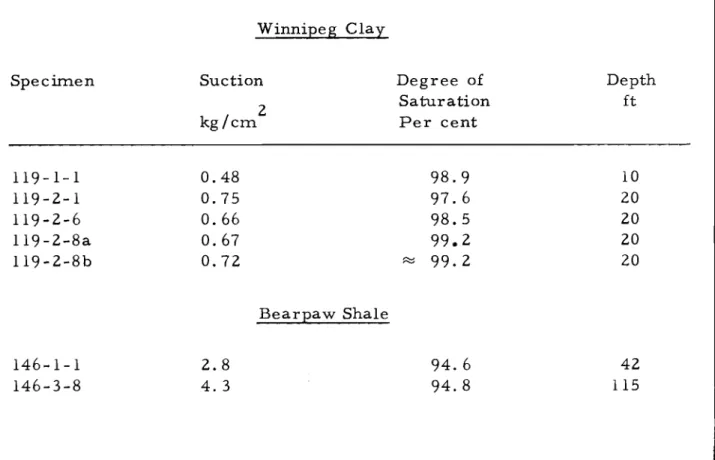
TABLE III
SWELLING PRESSURE DETERMINED FROM SUCTION MEASUREMENTS
METHOD II
Winnipeg Clay
Specim.en Suction Degree of Depth
2 Saturation ft
kgfern. Per cent
119-1-1 0.48 98.9 10 119-2-1 0.75 97.6 20 119-2-6 0.66 98.5 20 119-2-8a 0.67 99.2 20 119-2-8b 0.72 :::::: 99.2 20 Bearpaw Shale 146-1-1 2.8 94.6 42 146-3-8 4.3 94.8 115
SWELLING PRESSURES DETERMINED FROM OEDOMETER TESTS Winnipeg Clay Specimen Suction kg/cm 2 Degree of Saturation
%
Depth ft Method 119-1-2 0.54 95.6 10 V 119-2-18 0.48 95.3 20 V 119-2-13 1. 01 95.4 20 IV 119-2-12 0.50 97.2 20 III 119-2-14 0.59 96.1 20 III 119-2-16 1. 08 96.4 20 III Bearpaw Shale 146-3-9 4. 1 115 VB (Montmorillonite)
Effective stress
Uk
=
Capillary tension
=
Swelling pressure
e-,
...
'
... ---..., A
(Kaolinite)
...
---
---.
+
>0
- -
>
0
エMMMMセMMMMMMMMMMMMM⦅⦅NN
<J
FIGURE 1
ASSUMED VOLUME CHANGES FOR A KAOLINITE CLAY
AND A MONTMORILLONITE CLAY
•
•
Triaxial consolidation
Winnipeg Clay
Depth 20 ft
r---0.65
kg/cm 2
oャMMMセMMMMMMMMMMMMM⦅⦅⦅i
+2
- 4 '---_ _
...L..-_ _----J.. ..L....-_ _...;;::s._---'o
1
2
3
4
5
CONSOLIDATION PRESSURE,
セL
kg/cm2
-2
+ 20
+15
Triaxial consolidation
fit.