HAL Id: hal-03046763
https://hal-amu.archives-ouvertes.fr/hal-03046763
Submitted on 20 Apr 2021
HAL is a multi-disciplinary open access
archive for the deposit and dissemination of
sci-entific research documents, whether they are
pub-lished or not. The documents may come from
teaching and research institutions in France or
abroad, or from public or private research centers.
L’archive ouverte pluridisciplinaire HAL, est
destinée au dépôt et à la diffusion de documents
scientifiques de niveau recherche, publiés ou non,
émanant des établissements d’enseignement et de
recherche français ou étrangers, des laboratoires
publics ou privés.
Hydrogen trapping in tungsten: impact of helium
irradiation and thermal cycling
Mykola Ialovega, Elodie Bernard, Régis Bisson, Céline Martin, Ryuichi
Sakamoto, Arkadi Kreter, Etienne Hodille, Thierry Angot, Christian Grisolia
To cite this version:
Mykola Ialovega, Elodie Bernard, Régis Bisson, Céline Martin, Ryuichi Sakamoto, et al..
Hydro-gen trapping in tungsten: impact of helium irradiation and thermal cycling. Physica Scripta, IOP
Publishing, 2020, T171, pp.014066. �10.1088/1402-4896/ab68bd�. �hal-03046763�
Irradiation and Thermal Cycling
Mykola Ialovegaa,b, Elodie Bernarda, R´egis Bissonb,
Celine Martinb, Ryuichi Sakamotoc, Arkadi Kreterd, Etienne Hodillee, Thierry Angotb, Christian Grisoliaa
aCEA, IRFM, F-13108 Saint Paul-lez-Durance, France bAix Marseille University, CNRS, PIIM, Marseille, France
cNINS, National Institute for Fusion Science, Toki, Gifu 509-5292, Japan dForschungszentrum J¨ulich GmbH, Institut f¨ur Energie- und
Klimaforschung-Plasmaphysik, 52425 J¨ulich, Germany
eUniversity of Helsinki, P.O. Box 33 (Yliopistonkatu 4), 00014 Helsinki, Finland
E-mail: mykola.ialovega@cea.fr
Abstract.
The impact of helium (He) plasma exposure with He fluxes relevant for ITER and WEST on the near-surface microstructure of polycrystalline tungsten (W) is investigated by coupling transmission electron microscopy (TEM) analysis and thermal desorption spectrometry (TDS) measurements. The samples were exposed in the PSI-2 linear plasma device to 75 eV He ions up to the fluence of 3 × 10²³He m−2 with the surface temperature in the range 1053–1073 K.
The obtained He bubbles– enriched W samples are subsequently probed with sequences of low flux and low fluence 250 eV deuterium (D) ion implantations and TDS measurements in an ultra-high-vacuum setup to study the effects of the near-surface morphology changes due to the helium irradiation on fundamental mechanisms of deuterium retention. The results obtained for two different near-surface layer He bubbles morphologies revealed that the effects of He irradiation on D retention in W strongly depend on its subsequent thermal cycling. For annealing below 900 K, deuterium retention is similar to the one measured in pristine W. In contrast, for annealing above 1150 K, deuterium retention in the He bubbles enriched W is increased 3 to 8-fold as compared to non-damaged W. Additionally, the deuterium desorption peak shifts from 540 to 450 K. This increase of D trapping in the He bubbles enriched W annealed above 1150 K is presumably associated with a modification of the near-surface microstructure concurrent with an outgassing of He.
Keywords: Tungsten, Hydrogen trapping, Helium bubbles, Thermodesorption, Transmission electron microscopy
Hydrogen Trapping in Tungsten: Impact of Helium Irradiation and Thermal Cycling 2 1. Introduction
Investigations of hydrogen isotopes and helium reten-tion in plasma facing components (PFC) that are ex-posed to various plasma conditions are important for future fusion devices such as ITER and DEMO. Tung-sten (W) has been chosen as the plasma-facing mate-rial of the ITER divetor due to its favorable physical properties like low sputtering yield, high melting tem-perature and high thermal conductivity. However, in the deuterium/tritium phase of ITER, W PFC will ex-perience incident particles flux composed of hydrogen isotopes (HI), helium (He), other impurities and neu-trons. Their interaction with PFC may modify the retention properties of tungsten.
In the past years considerable work has been carried out to estimate the implantation and retention of HI and He in ITER. On the one hand [1, 2], it was con-cluded, that without considering the effect of the pres-ence of He in the bulk of polycrystalline tungsten PFC, the tritium inventory remains in tolerable limits and should not reach the 700 g safety limit in the ITER vacuum vessel. On the other hand, intensive He fluxes affect the PFC material causing erosion and damage formation on W surfaces as well as create damages in the W bulk. Highly porous structures, so–called W “fuzz” nanostructures, are formed when W is sub-mitted to low energy He irradiation at temperature above 1100 K [3, 4]. At lower temperatures, undulat-ing surface structures that depend on the grain ori-entation as well as numerous holes may appear on W surfaces [5, 6]. Furthermore, helium irradiation affect the near–surface region of W PFC causing the forma-tion of helium bubbles and dislocaforma-tion loops [7]. It has been already shown that the presence of He bubbles in tungsten and other metals strongly modifies the HI re-tention, with a complex interplay of the He/D kinetic energy ratio and flux ratio [8]. For He kinetic energy above 500 eV, displacement damage such as vacancies and dislocations are created during He irradiation re-sulting in an increase of D retention in W [9]. In con-trast, for He kinetic energy below 500 eV there is no displacement damage and it is generally measured a decrease of D retention in W [10]. This reduction of D retention in absence of displacement damage is cur-rently explained by the presence of He bubbles. These He bubbles could act as a bulk diffusion barrier for deu-terium and/or the He bubbles would formed intercon-nected pathways that ease D diffusion to the surface. Recently, Markel et al. [11] have used heavily damaged W to prepare a dense He implantation zone without He bubbles. They observed that D retention increases in the He implanted zone suggesting that vacancies, va-cancy clusters and dislocations decorated with He are additional trapping sites. However, the local effect of He bubbles on D retention has not been measured up
to now.
In the ITER divertor strike–points particle fluxes are expected to be of the order of 1024ions m−2s−1, and
W PFC surface temperature to be about 1100 K [12]. Due to the low kinetic energy of the particles in the divertor region (<100 eV), the implantation range of the incident helium ions is expected to be on the order of several nanometers and He bubbles may be created. Thus, the near surface layer of W PFC enriched with helium might have different retention properties than the bulk of W PFC. This conclusion provides the aim of this study i.e. to explore the effects of near-surface morphology change due to the low energy helium ir-radiation on HI retention in W and give more insight into the fundamental interaction of D and He induced defects in W, in particular in case of He bubbles. The helium irradiation parameters are chosen to be as close as possible to ITER conditions, i.e. at high He flux (up to 2.3 × 10²²He m−2s−1) and high W PFC
tempera-tures (up to 1073 K). Such implantation conditions are also relevant for the C4 helium campaign in the WEST tokamak, where the particle fluxes in the divertor re-gion are expected to be around 1021He m−2s−1.
In the present paper, the impact of ITER relevant he-lium irradiation on the W surface and near-surface layer is investigated by scanning electron microscopy and cross-sectional transmission electron microscopy analysis. Additionally, low energy and low flux deu-terium implantation at room temperature is used as a probe, together with in situ thermo-desorption spec-trometry (TDS), to investigate the fundamental mech-anisms of HI retention in the He enriched near-surface layer. Finally, the effect of thermal sweep (cycling) on deuterium retention in the He enriched near-surface layer is investigated with TDS and discussed.
2. Experiment
Two polycrystalline tungsten samples (99.995%, Toho Kinzoku Co. Ltd.) were mechanically polished and annealed at 1773 K in vacuum for 2 h. They were exposed to a low-temperature helium plasma in the linear plasma device PSI–2 [13] in J¨ulich (Germany). The samples were biased at 100 V, the typical inci-dent helium kinetic energy was expected to be 75 eV therefore below the W sputtering threshold energy by He [14]. Incident helium fluxes were estimated to be 2.3 × 10²²He m−2s−1 at 1053 K (high flux (HF) con-ditions) and 2.9 × 10²⁰He m−2s−1 at 1073 K (low flux (LF) conditions). Exposure time was 13 sec in the HF case and 1034 sec in the LF case to obtain an identi-cal helium fluence of 3 × 10²³He m−2 on both samples.
Before switching on the plasma, the samples were pre-heated up to 1073 K (LF) or 1053 K (HF) by a resistive heater installed on the sample carrier under the
sam-ples. In the case of the HF sample, the heating was turned off during the plasma exposure. For the LF case, the heating power was gradually reduced during the exposure in order to keep the sample temperature constant. Additional increase in temperature due to the plasma heating during exposure for both cases was well below 100 K. After the exposure, the samples were cooled down to room temperature (RT) within a few minutes. Detailed information about the layout of the PSI-2 device, its parameters and operational conditions can be found in [13]. The main impurity content in PSI-2 (oxygen) is of the order of 0.1% [15].
HF and LF samples were then introduced into the ultra-high-vacuum setup CAMITER (base pressure < 2.3 × 10⁻⁷Pa) in Marseille (France) for in situ
deu-terium implantation and TDS experiments [16, 17]. Firstly, the surfaces of the samples were “cleaned” by an initial outgassing with a TDS ramp of 1 K s−1up to 800-870 K in order to desorb loosely bound impurities such as water molecules and hydrocarbons. This step is usually performed in Marseille on all introduced sam-ples prior to D implantation since it has been shown that this “cleaning” procedure allows to have repro-ducible D retention measurement at low D fluence, i.e. when the measured D retention is on the order of a monolayer (1019D m−2) or less [17]. Note that the TDS range up to 800-850 K corresponds to the typical D re-tention temperature interval in pristine W and remains at least 200 K lower than the He irradiation tempera-ture. Then, D+2 ion implantation and subsequent TDS measurements up to 1200-1350 K were repeated 5 times (implantation-TDS experiments). Deuterium implan-tation was realized with an Omicron ISE 10 sputter ion gun at RT with flux of 1.7 × 10¹⁶D m−2s−1 and
fluence of 4.5 × 10¹⁹D m−2. The incident kinetic
en-ergy per deuterium ion of 250 eV/D is also below the W sputtering threshold [18]. The implantation depth of 250 eV D ions is ∼15 nm according to SRIM cal-culations [19]. A multiplexed Quadrupole Mass Spec-trometer (QMS) was used to record simultaneously the outgassing of HI molecules, i.e. of H2, HD and D2,
as well as He atoms during TDS. It was possible to distinguish between outgassing of He and D2 thanks
to their different electron ionization energy thresholds. The QMS count rate signal at m/z=4 was recorded at two different electron energy, one below the ionisation threshold of He (only D2contributes to the m/z=4
sig-nal) and the other above the ionisation threshold of He (both D2and He contribute to the m/z=4 signal). The
He desorption rate was therefore deduced by subtrac-tion of the D2 signal as determined for the electron
energy below the ionization threshold of He, and cor-rected for electron energy dependent ionization cross sections. Additionally, the D2 signal originating from
the molybdenum sample holder was subtracted to
ob-tain the sample D2 desorption rate. Statistical errors
were propagated accordingly. Unfortunately, during the experiments on the LF sample, a problem of tem-perature control occured and the obtained TDS spectra present several desorption rate bumps related to tem-perature rate spikes in the deuterium desorption range. This makes the TDS data interpretation more difficult and thus the TDS spectra of deuterium is not shown for the LF case. Nevertheless, the time-integrated TDS spectra for the LF case remain suitable for deuterium retention and helium outgassing quantification. The transmission electron microscopy (TEM) investi-gation allowed cross-sectional observation of the effects of helium plasma exposure in the near-surface layers of the samples. It was performed using TEM on thin lam-inae that were cut on both samples with the focused ion beam (FIB) technique. Scanning electron microscopy (SEM) allowed to observe the surface morphology of the samples after the helium irradiation.
3. Results and discussion
3.1. Sample surface SEM observation and cross–sectional TEM analysis after the helium irradiation
The surface morphology of the helium exposed tungsten changes significantly as compared to the non-exposed samples that has been shown earlier by Sakamoto et al. [5]. Figure 1 a) (resp. b)) shows the surface at different grains and c) (resp. d)) a close up within one grain of the LF (resp. HF) sample obtained by SEM after the helium irradiation. Helium irradiation in PSI–2 caused the appearance of holes of about 10 to 30 nm in diameters on the surfaces of both samples. This hole formation is observed on all grains of the samples (see figure 1 a) and b)) and thus, does not depend on the grain orientation. Considering the sputtering yield of oxygen on W to be ∼ 2 × 10⁻² [18, 20, 21], it is estimated that about 40% of W atoms of the first surface plane will be sputtered because of impurities in PSI-2 plasma in the LF and HF samples. This is not sufficient to explain the observed holes. However, the present SEM observations are consistent with the ones presented in [4] because the He irradiation surface temperature is at the threshold for nanostructure formation (∼1050 K). Molecular dynamics simulations done by Sefta et al. [22] have shown that holes (or so-called craters) formation on the W surface occurs in this temperature range because of the growth and pressure evolution of helium bubbles below the surface. The accumulation of helium in bubbles results into bubble growth towards the free surface. Overpressurized bubbles may undergo pressure relief through surface deformation by cratering and further
Hydrogen Trapping in Tungsten: Impact of Helium Irradiation and Thermal Cycling 4
Figure 1. Scanning electron microscopy images of tungsten irradiated with 75 eV helium ions at a fluence of 3 × 10²³He m−2before the set of deuterium implantation-TDS experiments. a) and c) for low flux (LF) conditions i.e. 2.9 × 10²⁰He m−2s−1at 1073 K. b)
and d) for high flux (HF) conditions i.e. 2.3 × 10²²He m−2s−1at 1053 K. A closer view on one of the grains for c) LF and d) HF
conditions.
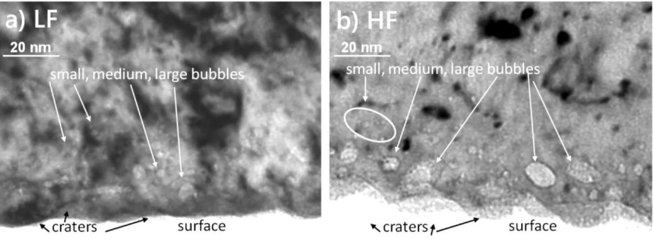
Figure 2. Transmission electron images of tungsten irradiated with 75 eV helium ions at a fluence of 3 × 10²³He m−2at different
fluxes of a) 2.9 × 10²⁰He m−2s−1at 1073 K (low flux (LF)) and b) 2.3 × 10²²He m−2s−1at 1053 K (high flux (HF)) before the set
of deuterium implantation–TDS experiments.
helium release. He bubble growth occurs in our samples as shown in figure 2.
Figure 2 shows the typical TEM micrographs of
tungsten irradiated with He in a) LF at 1073 K and b) HF at 1053 K conditions before the set of deuterium implantation–TDS experiments. After the helium
plasma exposure at 1053–1073 K, helium bubbles of different size are observed in the bulk of both tungsten samples. In the LF case, few large helium bubbles (d∼10 nm) and numerous smaller bubbles are present in the near–surface region. Analysis of the laminae showed that there are 2 times more large bubbles formed in the HF case than in the LF case and they are mostly located in the first 20 nm below the surface. The exposure time is much shorter in the HF case (13 sec) as compared to the LF case (1034 sec), thus, helium trapping at pre-existing natural defects through diffusion is reduced in the HF case. On the other hand, the possibility of helium self–trapping is expected to increase as the helium density in the implantation zone is higher since the He flux has been increased at constant temperature in the HF case. Thus, larger helium bubbles close to the surface can be formed in the HF case. The small bubbles (d∼1-2 nm) are distributed deeper than the large ones in both samples. These depths are well beyond the He implantation range, which is around 2 nm according to SRIM calculations. During He irradiation at 1053–1073 K, helium atoms are highly mobile in tungsten and, in addition to self-trapping, they can be trapped at natural defects such as vacancies [23] and dislocations far deeper than the implantation range [7].
3.2. Thermodesorption analysis
SEM and cross-sectional TEM analysis showed that He irradiation in PSI–2 creates a He bubbles enriched near-surface layer of ∼40 nm in LF and HF samples. In particular, the largest He bubbles are located in the first 20 nm in both samples. The effect of this near-surface layer of large He bubbles on hydrogen isotopes retention is now probed with low flux – low fluence deuterium implantation which kinetic energy (250 eV/D) is set to allow a ∼15 nm deep implantation without further defect creation.
Figure 3 a) shows the amount of outgassed helium for LF and HF samples at each step of the experimental campaign: initial TDS outgassing (“cleaning” in the following) and sequence of deuterium implantation– TDS experiments. Initial “cleaning” up to 800– 870 K induced a small outgassing of helium of (4.2 ± 0.6) × 1018He m−2 (LF) and (2.6 ± 0.4) × 1018He m−2
(HF). The majority of He outgassing occurs during the first TDS ramp up to 1170 (LF) and 1250 K (HF) where (3.8 ± 0.2) × 1019He m−2(LF) and (1.9 ±
0.2) × 1019He m−2 (HF) are measured. The total
amount of helium desorbed during the initial TDS “cleaning” and all implantation–TDS experiments is around 5.0 × 10¹⁹He m−2 (LF) and 2.7 × 10¹⁹He m−2 (HF) or 0.017% (LF) and 0.009% (HF) respectively to the initial helium irradiation fluence. These results suggest that helium is still retained in the samples,
presumably in the numerous small and large bubbles. It could eventually be released at higher temperatures which should be checked in future works.
Figure 3 b) shows the amount of outgassed deuterium, so-called deuterium retention, for the implantation–TDS experiments. The first implantation– TDS sequence is performed on W samples when most of helium is still present in the near–surface region and resulted in a small amount of deuterium trapped in both samples: about (0.7 ± 1.4) × 1018D m−2(LF) and
(1.6 ± 2.2) × 1018D m−2 (HF) is released during the TDS. These deuterium quantities are smaller than the He desorbed during the initial TDS and similar to deu-terium retention of about 1.7 × 10¹⁸D m−2 obtained on non-damaged polycrystalline W samples from the same manufacturer and from samples produced by ALMT with similar annealing procedures [17]. The typical TDS spectra for the case of non-damaged poly-cristalline W sample is the same for both manufactur-ers and an example for the manufacturer used in the present study is shown in 3 c) (grey dots): it con-sists in a single deuterium desorption peak starting at 320 K, peaking at 450 K and having a desorption tail up to 700 K. In contrast, the deuterium desorption peak of the first deuterium implantation-TDS experi-ment for the He irradiated HF sample is centered at a higher temperature (∼540 K, figure 4 c)) but is still within the non-damaged desorption range. The shift to higher temperature of the deuterium desorption peak following He irradiation could be the result of: an in-creased D trapping energy, an inin-creased D diffusion length and/or an increased stability of D atoms at the modified surface. A modification of the surface ad-sorption properties could be induced by the presence of oxygen impurities in PSI-2, indeed. However, Whit-ten and Gomer [24] have shown that an increase of oxygen surface coverage shifts the position of the des-orption peak to lower temperature, i.e. the opposite of our observation after He irradiation in PSI-2. Be-sides, an increased D diffusion length would result in an increase of D retention as compared to pristine W, which we do not observe. Therefore, our observation that the D desorption peak shifts to higher temper-ature by ∼100 K after He irradiation should indicate that the presence of He bubbles increases slightly the deuterium trapping energy. It can be noted that this D desorption peak corresponding to the traps in the He bubbles enriched near-surface layer is similar to the first He desorption peak from the initial TDS “clean-ing” (figure 4 a) and b)). However, the fact that the He desorption rate in the 540 K “cleaning peak” is 10 times smaller than the D desorption rate after D im-plantation in the cleaned sample prevents to conclude on a link between these He and D desorption peaks.
Hydrogen Trapping in Tungsten: Impact of Helium Irradiation and Thermal Cycling 6
Figure 3. Thermo-Desorption Spectrometry results for two tungsten samples pre–irradiated in 75 eV helium ions: at a same fluence of 3 × 10²³He m−2 but at different fluxes of 2.9 × 10²⁰He m−2s−1 at 1073 K (low flux) and 2.3 × 10²²He m−2s−1 at
1053 K (high flux). a) Outgassed amount of He and b) outgassed amount of deuterium (so-called deuterium retention) for each D2+ 500 eV implantation–TDS sequence (each implantation fluence is 4.5 × 10¹⁹D m−2). Temperatures above each bar indicate
the highest temperature reached during each TDS cycle. Grey dashed line represents the deuterium retention for the non-damaged polycristalline (PC) W sample.
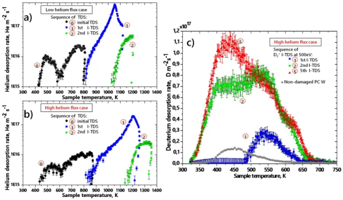
Figure 4. Thermal desorption spectra (TDS) for two tungsten samples pre–irradiated in 75 eV helium ions: at a same fluence of 3 × 10²³He m−2 but at different fluxes of 2.9 × 10²⁰He m−2s−1at 1073 K (low flux (LF)) and 2.3 × 10²²He m−2s−1 at 1053 K
(high flux (HF)). TDS spectra of helium for the a) LF case and b) for the HF case. c) TDS spectra of deuterium for the HF sample. Circled numbers denote the sequence number in the deuterium implantation–TDS (I-TDS) experiment (each implantation fluence is 4.5 × 10¹⁹D m−2). In case of the initial TDS up to 800 K (LF) and 850 K (HF) no deuterium was implanted. Grey dots represent
the typical TDS spectra for the non-damaged polycristalline (PC) W sample.
both samples, He outgassing is maximal in the thermodesorption phase of the 1st D implantation– TDS sequence well after the desorption of deuterium
and reaching a peak of outgassing rate at 1050 K (resp. 1200 K) in the LF (resp. HF) case. About 3.8 (resp. 1.9) ×1019He m−2 is outgassed in this
single temperature sweep, ten times more than in the next implantation-TDS sequences. The maximal He outgassing is accompanied with a drastic change in the deuterium retention and deuterium TDS spectra for the subsequent (2nd) D implantation–TDS sequence (figure 4 c)). The next three implantation–TDS sequences up to 1200-1350 K consolidate the evolution of deuterium retention and TDS spectra, concurrent with a small He outgassing. The deuterium desorption peak shifted to 450 K, with a shape similar of non-damaged W but with a D retention increased up to 8 times: deuterium retention rapidly saturates for each D implantation–TDS sequence around 0.8×10¹⁹D m−2 (17% of the deuterium fluence) for LF and around 2 × 10¹⁹D m−2 (41% of the deuterium fluence) for HF.
At first glance, it appears that the lesser helium remains in the samples, the more deuterium is trapped. This suggests that deuterium may occupy the emptied trapping sites of the He bubbles enriched near-surface layer. But this does not explain the fact that for the lesser helium release in the HF case, the deuterium trapping is higher than in the LF case. Actually, the amount of D retention in the HF sample is on a par with the He outgassing while, for the LF sample, the D retention is 5 times smaller than the outgassed He. The difference of behavior in terms of D retention for low flux (LF) and high flux (HF) samples may be related with the higher density of the large helium bubbles in the HF case (see figure 2) and the helium content that is inside the bubbles. Since the total helium content in both samples is unknown at the moment, it is not possible to conclude on the density of He inside the bubbles. However, a preliminary comparison of laminae cut on different grains on both samples before and after the implantation–TDS experiments show the disappearance of the small He bubbles in the first few nanometers from the surface while slightly larger bubbles remain in the near-surface layer. These preliminary TEM observations support the following interpretation of our results in the frame of the literature work for He irradiation with kinetic energy below the displacement damage threshold. After He irradiation and for annealing below the He irradiation temperature, D diffusion is slowed down by the presence of numerous small He bubbles in the few nanometer layer below the surface, which binding energy is slightly higher than natural defects in pristine W, thus limiting D retention. For annealing above the He irradiation temperature, small He bubbles diffuse and disappear in the first few nanometer layer below the surface leaving a pristine W decorated with larger He bubbles where D can diffuse and bind to the bubbles periphery, thus increasing the D retention. Indeed, DFT and MD studies [25, 26, 27] have shown that deuterium atoms bind around
He-vacancy clusters complexes and ∼2 nm He bubbles with a large binding energy range of 0.8–2.0 eV consistent with our broad D desorption peak. Our interpretation is also consistent with the following observation: a higher He release for the LF sample but a higher D retention for the HF sample. For long He irradiation at low flux (LF sample), a greater number of small He bubbles than large He bubbles is obtained because of greater time allowed for He diffusion and a smaller He density. These small bubbles being more mobile, they will lead to a high He release upon annealing. In contrast, a short high flux He irradiation (HF sample) will lead to a stronger self-trapping favoring large He bubbles over small He bubbles. Thus, less He release and more D retention. Of course, more sophisticated statistical analysis on density and size of the bubbles is necessary and will be the subject of future systematic studies. In particular, we plan to investigate the evolution of the microstructure at each step of the implantation-TDS experiments presented here. Nevertheless, the current experimental results already highlight that the helium content in the samples and the helium bubbles morphology and their density are important parameters responsible for the modification of hydrogen isotopes retention in tungsten.
4. Summary and perspectives
In this paper, thermodesorption spectrometry tech-nique combined with transmission electron microscopy observations were used to study deuterium retention in polycrystalline tungsten exposed to helium plasma. Ir-radiation by helium in conditions relevant to ITER and WEST (3 × 10²³He m−2 at 1053–1073 K) caused the appearance of helium bubbles of different size near the surface. He bubbles located within 20 nm of the surface are probed by a set of sequential low fluence deuterium ion implantation/desorption experiments up to 1200– 1350 K. The obtained TDS spectra and deuterium re-tention results indicate an important effect of the ther-mal cycling of He-irradiated W on deuterium retention. At low deuterium fluence, the deuterium retention in the He bubbles enriched near-surface layer is initially similar than for pristine W but with a slightly higher binding energy. After thermal cycling above the He ir-radiation temperature, the D binding energy is lowered to a similar value range as for pristine W but the deu-terium retention is increased 3 to 8-fold as compared to non-damaged polycrystalline W. The modification of D retention upon thermal cycling appear to be linked with the density of various He bubbles. We rational-ize the increase of deuterium retention upon annealing above the He irradiation temperature, with the evolu-tion of the helium bubbles morphology distribuevolu-tion in
Hydrogen Trapping in Tungsten: Impact of Helium Irradiation and Thermal Cycling 8 tungsten following thermal cycling.
In the future development of our work, we will deter-mine the total helium content in the samples and focus on structural analysis of He bubbles and surface mor-phology evolution with stepwise thermal cycling.
Acknowledgement
The project leading to this publication has received funding from the Excellence Initiative of Aix-Marseille University - A*Midex, a French “Investissements d’Avenir” programme as well as from the ANR under grant ANR-18-CE05-12.
This work has been also carried out within the framework of the French Federation for Magnetic Fusion Studies (FR-FCM) and of the EUROfusion Consortium and has received funding from the Euratom research and training program 2014-2018 and 2019-2020 under grant agreement No 633053. The views and opinions expressed herein do not necessarily express those of the European Commission.
The electron microscopy analysis was performed at FSCM-CP2M laboratory of Aix-Marseille University, France. In particular, we are grateful to Cabi´e M. and Campos A.
We gratefully acknowledge the helpful discussions with Dr. A. De Backer, Dr. J. Mougenot and Dr. M.-F. Barthe.
[1] Roth J, Tsitrone E, Loarte A, Loarer T, Counsell G, Neu R, Philipps V, Brezinsek S, Lehnen M, Coad P, Grisolia C, Schmid K, Krieger K, Kallenbach A, Lipschultz B, Doerner R, Causey R, Alimov V, Shu W, Ogorodnikova O, Kirschner A, Federici G and Kukushkin A 2009 Journal of Nuclear Materials 390-391 1 – 9 ISSN 0022-3115 proceedings of the 18th International Conference on Plasma-Surface Interactions in Controlled Fusion Device URL http://www.sciencedirect.com/science/ article/pii/S0022311509000506
[2] Hodille E A, Bernard E, Markelj S, Mougenot J, Becquart C S, Bisson R and Grisolia C 2017 Physica Scripta T170 014033 URL https://doi.org/10.1088%2F1402-4896% 2Faa8787
[3] De Temmerman G, Bystrov K, Zielinski J J, Balden M, Matern G, Arnas C and Marot L 2012 Journal of Vacuum Science & Technology A 30 041306 (Preprint https://doi.org/10.1116/1.4731196) URL https:// doi.org/10.1116/1.4731196
[4] Kajita S, Sakaguchi W, Ohno N, Yoshida N and Saeki T 2009 Nuclear Fusion 49 095005 URL https://doi.org/ 10.1088%2F0029-5515%2F49%2F9%2F095005
[5] Sakamoto R, Bernard E, Kreter A and Yoshida N 2016 Nuclear Fusion 57 016040 URL https://doi.org/10. 1088%2F1741-4326%2F57%2F1%2F016040
[6] Sakamoto R, Bernard E, Kreter A, Martin C, P´egouri´e B, Pieters G, Rousseau B, Grisolia C and Yoshida N 2017 Physica Scripta T170 014062 URL https://doi.org/ 10.1088%2F1402-4896%2Faa93a2
[7] Bernard E, Sakamoto R, Tokitani M, Masuzaki S, Hayashi H, Yamada H and Yoshida N 2017 Jour-nal of Nuclear Materials 484 24 – 29 ISSN 0022-3115 URL http://www.sciencedirect.com/science/ article/pii/S0022311516306560
[8] Zhou Q, Azuma K, Togari A, Yajima M, Tokitani M,
Masuzaki S, Yoshida N, Hara M, Hatano Y and Oya Y 2018 Nuclear Materials and Energy 16 76 – 81 ISSN 2352-1791 URL http://www.sciencedirect.com/ science/article/pii/S2352179117301606
[9] Iwakiri H, Morishita K and Yoshida N 2002 Journal of Nuclear Materials 307-311 135 – 138 ISSN 0022-3115 URL http://www.sciencedirect.com/science/ article/pii/S0022311502011789
[10] Miyamoto M, Nishijima D, Ueda Y, Doerner R, Kurishita H, Baldwin M, Morito S, Ono K and Hanna J 2009 Nuclear Fusion 49 065035 URL https://doi.org/10. 1088%2F0029-5515%2F49%2F6%2F065035
[11] Markelj S, Schwarz-Selinger T and Zaloˇznik A 2017 Nuclear Fusion 57 064002 URL https://doi.org/10. 1088%2F1741-4326%2Faa6b27
[12] Pitts R, Carpentier S, Escourbiac F, Hirai T, Komarov V, Lisgo S, Kukushkin A, Loarte A, Merola M, Naik A S, Mitteau R, Sugihara M, Bazylev B and Stangeby P 2013 Journal of Nuclear Materials 438 S48 – S56 ISSN 0022-3115 proceedings of the 20th International Conference on Plasma-Surface Interactions in Controlled Fusion Devices URL http://www.sciencedirect.com/ science/article/pii/S0022311513000160
[13] Kreter A, Brandt C, Huber A, Kraus S, M¨oller S, Reinhart M, Schweer B, Sergienko G and Unterberg B 2015 Fusion Science and Technology 68 8–14
[14] Ferroni F, Hammond K D and Wirth B D 2015 Jour-nal of Nuclear Materials 458 419 – 424 ISSN 0022-3115 URL http://www.sciencedirect.com/science/ article/pii/S0022311514010332
[15] Schmitz J, Litnovsky A, Klein F, Wegener T, Tan X, Rasinski M, Mutzke A, Hansen P, Kreter A, Pospieszczyk A, M¨oller S, Coenen J, Linsmeier C, Breuer U, Gonzalez-Julian J and Bram M 2018 Nu-clear Materials and Energy 15 220 – 225 ISSN 2352-1791 URL http://www.sciencedirect.com/science/ article/pii/S2352179117301023
[16] Hodille E, Ghiorghiu F, Addab Y, Zaloˇznik A, Minissale M, Piazza Z, Martin C, Angot T, Gallais L, Barthe M F, Becquart C, Markelj S, Mougenot J, Grisolia C and Bisson R 2017 Nuclear Fusion 57 076019 URL https://doi.org/10.1088%2F1741-4326%2Faa6d24 [17] Bisson R, Markelj S, Mourey O, Ghiorghiu F, Achkasov K,
Layet J M, Roubin P, Cartry G, Grisolia C and Angot T 2015 Journal of Nuclear Materials 467 432 – 438 ISSN 0022-3115 URL http://www.sciencedirect.com/ science/article/pii/S0022311515301148
[18] 2001 Atomic and Plasma–Material Interaction Data for Fusion (Atomic and Plasma–Material Inter-action Data for Fusion no 7/B) (Vienna: IN-TERNATIONAL ATOMIC ENERGY AGENCY) URL https://www.iaea.org/publications/4709/ atomic-and-plasma-material-interaction-data-for-fusion [19] Ziegler J F, Ziegler M and Biersack J 2010 Nuclear
Instruments and Methods in Physics Research Section B: Beam Interactions with Materials and Atoms 268 1818 – 1823 ISSN 0168-583X 19th International Conference on Ion Beam Analysis URL http://www.sciencedirect. com/science/article/pii/S0168583X10001862
[20] Eckstein W 2002 Calculated sputtering, reflection and range values (ipp 9/132)
[21] Hechtl E, Eckstein W, Roth J and Laszlo J 1991 Journal of Nuclear Materials 179-181 290 – 293 ISSN 0022-3115 URL http://www.sciencedirect.com/ science/article/pii/002231159190083J
[22] Sefta F, Juslin N and Wirth B D 2013 Journal of Applied Physics 114 243518 (Preprint https:// doi.org/10.1063/1.4860315) URL https://doi.org/ 10.1063/1.4860315
and Methods in Physics Research Section B: Beam Interactions with Materials and Atoms 255 23 – 26 ISSN 0168-583X computer Simulation of Radiation Effects in Solids URL http://www.sciencedirect.com/science/ article/pii/S0168583X06010585
[24] Whitten J and Gomer R 1998 Surface Science 409 16 – 26 ISSN 0039-6028 URL http://www.sciencedirect.com/ science/article/pii/S0039602898001885
[25] Becquart C and Domain C 2009 Journal of Nuclear Materials 386-388 109 – 111 ISSN 0022-3115 fusion Reactor Materials URL http://www.sciencedirect. com/science/article/pii/S0022311508008179
[26] Bergstrom Z J, Cusentino M A and Wirth B D 2017 Fusion Science and Technology 71 122–135 (Preprint https://doi.org/10.13182/FST16-121) URL https:// doi.org/10.13182/FST16-121
[27] Yang L and Wirth B D 2018 Journal of Applied Physics 123 215104 (Preprint https://doi.org/10.1063/1.5027805) URL https://doi.org/10.1063/1.5027805