HAL Id: inserm-00955103
https://www.hal.inserm.fr/inserm-00955103
Submitted on 30 Jun 2014HAL is a multi-disciplinary open access
archive for the deposit and dissemination of sci-entific research documents, whether they are pub-lished or not. The documents may come from teaching and research institutions in France or abroad, or from public or private research centers.
L’archive ouverte pluridisciplinaire HAL, est destinée au dépôt et à la diffusion de documents scientifiques de niveau recherche, publiés ou non, émanant des établissements d’enseignement et de recherche français ou étrangers, des laboratoires publics ou privés.
Metal artifact reduction in CT using fusion based prior
image.
Jun Wang, Shijie Wang, Yang Chen, Jiasong Wu, Jean-Louis Coatrieux,
Limin Luo
To cite this version:
Jun Wang, Shijie Wang, Yang Chen, Jiasong Wu, Jean-Louis Coatrieux, et al.. Metal artifact reduc-tion in CT using fusion based prior image.. Medical Physics, American Associareduc-tion of Physicists in Medicine, 2013, 40 (8), pp.081903. �10.1118/1.4812424�. �inserm-00955103�
! "!
!"#$%&$'#()$*#&'"+,*#(-.&(.&/0&,1(.2&),1(-.&3$1"+&4'(-'&(5$2"&
#$%!&'%(
")*)!+,-.-/
!&'%(
!'0!")*!)!1'%(!2,/%
")*)!#-'34%(!&$
")*)5)6)!#/'%784$-3!
24'9:-/$;
")*)5)6!'%<!8-=-%!8$4
")*!
! "#$%&'(%)'(*!'+!,-%./!012/31/!%34!5/163'7'.*!8$,059:!0';)6/%<)!=32>/(<2)*:!?%3@23.:! >! A2%3.<;!B"CCDE:!F623%! B#F/3)(/! 4/! G/16/(16/! /3! ,3+'(-%)2'3! H2'-/421%7/! 023'IJ(%31%2<! 8FG,H<9:! G/33/<! KLCMB:!J(%31/! K#,3</(-:!=NG!"CDD:!G/33/<:!JIKLCCC:!J(%31/! M#=32>/(<2)O!4/!G/33/<!":!$50,:!G/33/<:!JIKLCCC:!J(%31/! "?!Purpose: In computed tomography (CT), metallic objects in the scanning field create
artifacts in the reconstructed images. Interpolation-based methods for metal artifact
reduction (MAR) replace the metal-corrupted projection data with surrogate data
obtained from interpolation using the surrounding uncorrupted sinogram information.
Prior-based MAR methods further improve interpolation-based methods by better ">!
estimating the surrogate data using forward projections from a prior image. However,
the prior images in most existing prior-based methods are obtained from segmented
images and misclassification in segmentation often leads to residual artifacts and tissue
structure loss in the final corrected images. To overcome these drawbacks, we propose
a fusion scheme, named fusion prior-based MAR (FP-MAR). *?!
Methods: The FP-MAR method consists to: (i) pre-correct the image by means of an
interpolation-based MAR method and an edge-preserving blur filter; (ii) generate a
prior image from the fusion of this pre-corrected image and the originally reconstructed
image with metal parts removed; (iii) forward project this prior image to guide the
estimation of the surrogate data using replacement techniques. *>!
! *!
proposed FP-MAR method can effectively reduce metal artifacts. A comparison with
other MAR methods demonstrates that the FP-MAR method performs better in artifact
suppression and tissue feature preservation.
Conclusions: From a wide range of clinical cases to which FP-MAR has been tested
5?!
(single or multiple pieces of metal, various shapes and sizes), it can be concluded that
the proposed fusion based prior image preserves more tissue information than other
segmentation-based prior approaches and can provide better estimates of the surrogate
data in prior-based MAR methods.
Key words: computed tomography, metal artifact reduction, image fusion 5>!
67&6809:;</06:8& 67=7&:>"'>("?&
X-ray computed tomography (CT) has been widely used in clinical diagnosis for decades. Under normal circumstance,
modern CT scanners can provide high-resolution images with reliable anatomical information. However, if metallic
objects (such as dental fillings or prosthesis) are present in the scanning field, major artifacts often deteriorate the 6?!
reconstructed CT image quality and lower their diagnosis value. Metal artifact reduction (MAR) methods can however
be applied. They can be roughly classified into iterative reconstruction1-5, sinogram correction6-24, and hybrid
methods25-30. Iterative reconstruction and hybrid methods have shown a good performance in suppressing metal artifacts,
but their clinical applications are still limited due to their high computational cost. Sinogram correction methods remain
the most common and applicable ones. More details about sinogram correction methods are presented in the next 6>!
section.
67@7&A(.-2'$5&*-''"*#(-.&
In sinogram correction methods, the original sinogram is corrected before FBP reconstruction by replacing the
! 5!
projections16-24. The first step is to determine the metal trace occupied by the corrupted data in the sinogram space. To >?!
achieve this, a re-projection method is often used. An image is first reconstructed from the original sinogram. Then, the
metal parts are identified in the image domain by thresholding. Forward projection of the metal-only image yields the
metal-only sinogram, in which the nonzero pixels define the metal trace. A correction can then be performed to estimate
the surrogate data in the metal trace. Correction methods can be divided into two groups: interpolation-based
methods6-15and prior-based methods16-24. >>!
Interpolation-based methods estimate the surrogate data using interpolation type techniques. Linear interpolation (LI)
is the simplest way to do that6,8 . We refer them to LI-MAR in this work. In LI-MAR, the surrogate data are estimated
via linear interpolation using the uncorrupted data on the two sides of the metal trace along the channel ray??? direction.
Interpolation-based methods can effectively reduce the metal artifacts. However, due to the unavoidable loss of structure
information in the metal trace after interpolation, they often introduce new artifacts near the metallic objects. @?!
To overcome the drawbacks of interpolation-based methods, prior-based methods estimate the surrogate data using
forward projections from a prior image. The structure information from the prior image is brought back to the metal
trace and this way, better estimates can be obtained. Most existing methods, based on k-means clustering16,19 or
multithresholding17,18,23,24, build the prior images by segmenting the originally reconstructed images (the uncorrected
images) or pre-corrected images (via interpolation-based MAR) into different tissues such as air, soft tissue, and bone. @>!
We will call them TP-MAR methods since all are based on thresholding the prior images. One main limitation of
TP-MAR methods is their sensitivity to misclassification which can lead to some tissue structures lost. In Ref. 21, a
metal deletion technique (MDT) was proposed that used a LI-MAR corrected image as an initial prior image. Then, the
prior image was iteratively improved using the FBP reconstruction combined with an edge-preserving blur filter. Since
MDT was still based on the interpolation-based MAR, tissue structure loss near the metal objects was often observed. A?!
Another limitation of MDT is the high computational cost, about 19 times slower than FBP. Recently, a method based
! 6!
structures in the uncorrected image using shape and intensity information of metal artifacts. Then, the prior image was
generated by reassigning the CT values within the artifact region to the surrounding tissue values. The experiments on
head CT scans reported in Ref. 20 has shown that this method could generate more accurate prior images than TP-MAR A>!
methods, and could provide better image quality than both TP-MAR and interpolation-based MAR. Even though, its
performance and robustness, in the presence of different metal implants or more pieces of metals, still needs a further
verification, as pointed out by the authors.
667&!B0C:;
The quality of the prior image plays a crucial role in the performance of the prior-based MAR methods. To B?!
overcome the misclassification resulting from segmentation in TP-MAR methods, we choose to build the prior image
via the fusion of a pre-corrected image and the uncorrected FBP image. The main idea behind this new method (called
fusion prior-based MAR or FP-MAR in the following) is to jointly benefit from the well preserved structures in the
uncorrected FBP image and the suppressed artifacts in the pre-corrected one. We can see in Fig. 1 that much of the
original structure information is preserved in the fusion-based prior image. The FP-MAR method comprises three major B>!
steps: pre-correction, image fusion, and sinogram completion.
FIG. 1. The intermediate outputs in generating a prior image of a simulated hip phantom with bilateral prostheses. The uncorrected FBP
image, the LI-MAR image, and the pre-corrected image are shown in (a), (b), and (c), respectively. In (d), the uncorrected FBP image with metal parts removed. The difference image [subtract (d) from (c)], and the prior image obtained by fusion of (c) and (d), are depicted in (e)
C?!
! >! 667=7&D'"E*-''"*#(-.&
The pre-corrected image is here obtained by applying LI-MAR and next, an edge-preserving blur filter. The uncorrected
FBP image is first reconstructed from the original sinogram. Then, the re-projection method (see Sec. I. B) is used to
identify the metal trace. The metal parts are segmented by applying a simple threshold, set to 2000 Hounsfield unit C>!
(HU) . For dental filling cases, 3000 HU is used because human teethes usually have CT values above 2000 HU. After
determining the metal trace, the linear interpolation technique proposed in Ref. 8 is used for sinogram completion. Fig.
1(a) shows the uncorrected FBP image of a simulated hip phantom with bilateral prostheses which suffers a prominent
dark streak artifact between the two prostheses. Fig. 1(b) shows the result of LI-MAR, and it can be seen that the streak
artifact is significantly reduced but simultaneously newly artifacts are introduced and serious loss of the bone structures "??!
near the prostheses can be noticed.
An edge-preserving blur filter is then applied to suppress the newly introduced artifacts in the LI-MAR image. Each
value !!"!!! !! in the filtered image is the average value of pixels within a local square region around the pixel !!! !! in the LI-MAR image. To preserve tissue edges, only those pixels with CT numbers similar to the value of the center
pixel are included in the average: "?>! !!!!!!!!!!!!!!"!!! !! ! !!!!!!!!!! ! !!!! ! !!!! ! , (1)
where ! is the number of “similar pixels” in the square region of size ! with the indices!!! and q running from ! ! to !. !!! ! !! ! ! !! is defined as:
!!!!!!!!!!!! ! ! !! ! ! ! ! !!!!!!!!!!!!!!!!!!!!!!!!!!!!!!!!!!!!!! !! !" ! ! !! ! ! ! ! !!" !! ! ! !
!" ! ! !! ! ! ! !!!!!!!! !!" ! ! !! ! ! ! ! !!" !! ! ! ! , (2)
where !!" denotes the CT values in the LI-MAR image. ! is a user-defined threshold for the identification of the ""?!
similar pixels. ! and ! should be properly selected to achieve artifact suppression without blurring the main edges between air, soft tissue, and bones. Our experiments demonstrate that!!! ! !""!!" !"#!! ! !! can lead to good results for the all cases studied in this work. Fig. 1(c) illustrates the filtered result of the LI-MAR image (henceforth
! @! 667@7&65$2"&),1(-.&
"">!
This step aimed at building the prior image from the fusion of the pre-corrected image and the uncorrected FBP
image with metal parts removed. Fig. 1(d) shows the resulting metal-removed FBP image, in which the metal parts are
filled by the CT numbers taken from the metal regions in the pre-corrected image. This metal-removed FBP image is
then subtracted from the pre-corrected image to generate the difference image ! depicted in Fig. 1(e). The positive values with large magnitudes in ! correspond to the dark streak between the two prostheses, whereas the negative "*?!
values mainly represent the damaged bone structures. The prior image, !!"#$", is then built via the following pixel-wise fusion formula:
!!"#$"!!! !! ! ! !! ! !!!"#!!! !! ! ! ! ! !! ! !!!"#$!!! !!, (3)
where !!"# and !!"#$ denote the metal-removed uncorrected FBP image and the pre-corrected image, respectively. ! !! ! is the pixel-wise weighting factor in the interval !! ! , ]0,1] ?? and is calculated through Eqs. (4) and (5): "*>!
!!!!!!!!! !! ! ! !
!!!!"#$ !!!! !!, (4)
!!!!!!!!!!"#$!!! !! ! !! !!! !!!!!!"#!!!!!"#!"#, (5)
where !! ! ! ! ! and ! ! !. !!"#$ is the normalized version of the difference image !. !!"# and !!"# denote the maximum and the minimum values in !, respectively. Fig. 2 plots the ! !! ! in Eq. (4) when parameters ! and ! are set to 10 and 0.45. From Fig. 2 and Eq. (3), we can see that, when!!!!"#$ !! ! !!!"!!"#$%, a small weighting factor "5?!
! !! ! !!!"!!""#$%&!and leads to !!"#$"!!! !! close to the intensity in the pre-corrected image, thus suppressing the dark
! A!
artifacts. Conversely, a large weighting factor ! !! ! !!"!!"#$!!"# small values of !!!!"#$ !! ! !! in order to get !!"#$"!!! !! close to the intensity in the metal-removed uncorrected FBP image, thus preserving tissue structures.
"5>!
Parameters ! and ! should be suitably set to ensure both effective tissue preservation and artifact suppression for the prior image. Figs. 3(a)-3(d) show that a small ! may lead to severe residual dark artifacts, and the fusion is no longer sensitive to ! when ! is larger than 10 in this case (little difference is observed when increasing !!!from 10 to 40). Setting parameter ! is application-dependent. A small !! value would generate a fusion image similar to the pre-corrected image, while a large ! would make the result close to the metal-removed uncorrected FBP image (see Fig. "6?!
3, bottom row). Thus, a small ! value (for example, 0.1) should be retained for cases where small and regular metal objects are present (such situations are often the ideal applications for LI-MAR), while it should be increased (for
example, to 0.45) for irregular and large metal objects to overcome the possible serious loss of tissue structures near the
metal objects.
"6>!
FIG. 3. Illustration of the fusion result for different settings of ! and !. Window settings: C=400 HU/W=1500 HU.
667/7&A(.-2'$5&*-54%"#(-.&
After fusion, the prior image as shown in Fig. 1(f) is obtained and this prior image is forward projected to produce a
prior sinogram for the estimation of the surrogate projection data. This is achieved by using the difference-based
interpolation method proposed in Ref. 31. In this method, the prior sinogram is first subtracted from the original ">?!
! B!
prior sinogram to create the corrected sinogram. Here, the built-in linear interpolation is performed via the linear
interpolation technique in Ref. 8. Finally, the artifact-reduced image is reconstructed from the corrected sinogram and
the metal objects identified in the uncorrected FBP image are superimposed on this image to indicate metal objects.
6667&A6!<F=06:8A&=8;&/F686/=F&6!=GB&0BA0A&
">>!
Simulations were performed to evaluate the proposed FP-MAR method. As shown in Fig. 4, we generated two
phantoms with metal artifacts produced from bilateral hip titanium prostheses and from pedicle screws, respectively.
The original true phantoms without metallic objects are also displayed in Fig. 4 to serve as reference. With 2D fan beam
scans assumed, the simulations modeled the CT scanning data using the CatSim model32 which incorporates
polychromaticity, realistic quantum and electronic noise models, non-linear partial volume effect, and scatter. The main "@?!
simulation parameters were 70 kV, 108 initial photons per ray, 103 scatter photons per detector element, 768 channels,
and 720 views per rotation. 10 rays were simulated per detector to preserve the finite width of beams.
As presented in Fig. 6 and Fig. 7, seven clinical cases were selected to test the capability of the proposed FP-MAR
method in coping with different kinds of metal artifacts in standard clinic. All the original uncorrected images,
"@>!
FIG. 4. The two simulated phantoms. The left and right sides depict respectively the phantoms with and without inserted metallic objects.
Window settings: C=100 HU/W=700 HU.
with DICOM format, were obtained from the REVISION RADIOLOGY group (http://www.revisionrads.com/cgi-bin/MDT_cgi). To be more precise, the metal artifacts in the three sets of clinical images in Fig. 6 are respectively caused by a deep brain stimulator (Case 1), bilateral hip prostheses (Case 2), and small "A?!
metal implants (Case 3). Compared to Fig. 6, Fig. 7 includes four more challenging cases with multiple metal implants of large size and irregular shapes. The metal artifacts of these four cases are respectively produced from unilateral hip prostheses (Case 4), sternum fixation screws (Case 5), pedicle screws (Case 6), and dental fillings (Case 7). For each case, the original sinogram was simulated by forward projecting the tested clinical images. The resolution of the CT image is !"#!!"# pixels and the simulated sinogram is of !"#!!"## pixels (3600 views over 360°).
! C!
In the implementation of the proposed FP-MAR method, ! ! !" and!!! ! !!!" were used in simulations. For the clinical image experiments, ! ! !" was used in all cases;
t
was set to 0.1 for the three cases reported in Fig.6 and to 0.45 for the four challenging cases illustrated in Fig. 7. For comparison, the LI-MAR and TP-MAR methods were alsoimplemented. We applied LI-MAR by using the pre-correction step procedure above (Sec. II. A)D! To generate the
TP-MAR prior image, the uncorrected FBP image was first smoothed using the edge-preserving blur filter described in "B?!
Sec. II.!ED Then, the filtered result was segmented into air, soft tissue, bone, and metals using the k-means clustering
described in Ref. 16 with the initial clustering center -950 HU, 200 HU, 750 HU, and 5000 HU. After segmentation, the
air regions were set to -1000 HU, the soft tissue and metal parts to 0 HU while bone pixels kept their original intensities
as suggested in Ref. 18. Then, the data replacement for the metal trace was completed by the above difference-based
interpolation method described in Sec. II.! 2. Since the interpolation technique is the same for all methods, the prior "B>!
image determines the improvement. In addition, we collected the clinical MDT results from the REVISION
RADIOLOGY group for comparison. All the CT images were processed under a PC workstation (Intel Core 2 Duo CPU
2.93 GHz processor and 2048 Mb RAM) under MATLAB R2009a version 7.8.0 (The MathWorks Inc., Natick, MA).
The fan-beam transform and the inverse fan-beam transform were used for the forward projection and filtered back
projection, respectively. "C?!
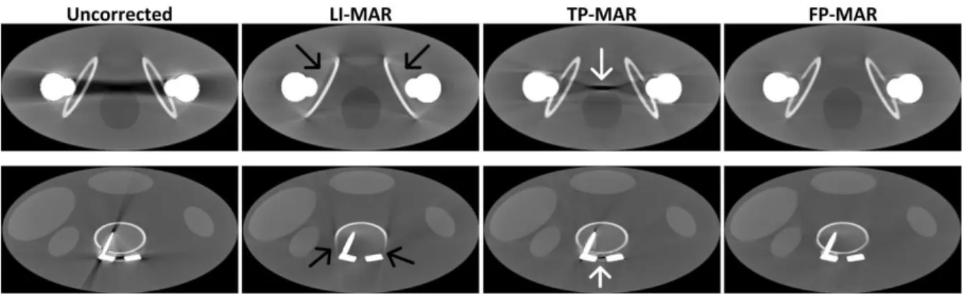
6H7&9BA<F0A&
Fig. 5 shows the correction results for the two simulations. We can see that the uncorrected images suffer from
severe beam hardening artifacts between the metal objects and all the LI-MAR, TP-MAR, and FP-MAR methods lead to
significant reduction of metal artifacts. However, in the LI-MAR results, some new artifacts are introduced and some
bone structures (indicated by black arrows) are missing near the metallic objects. When compared to LI-MAR, "C>!
TP-MAR yields better preserved bone structures, but some residual artifacts (indicated by white arrows) are also present
due to segmentation errors in the prior image. We can see in Fig. 5 that the proposed FP-MAR method leads to the best
! "?!
Fig. 6 illustrates the correction results for Case 1, Case 2, and Case 3. Severe streak artifacts tangent to the metallic
objects in uncorrected images are displayed. Many new streak-like artifacts remain when applying the LI-MAR *??!
correction, partially reduced by TP-MAR. However, the results of TP-MAR still show some residual metal artifacts,
especially for the Case 1. In comparison to TP-MAR, both MDT and FP-MAR bring significant improvements. For
these three cases, similar performance in artifact suppression is observed for FP-MAR and MDT. In Case 1, some tissue
structures on the right side of the metal object, indicated by the dotted arrow, are clearly visible after correction with
M D T a n d F P - M A R . T h e s t r u c t u r e i n d i c a t e d b y t h e d o t t e d a r r o w i n t h e z o o m e d r e g i o n o f *?>!
FIG. 5. Correction results of the two simulated phantoms. LI-MAR destroys the bone structures close to the implants (indicated by black
arrows in the second column). TP-MAR well preserves the bone structures but some metal artifacts remain (indicated by white arrows in the third column). FP-MAR (the fourth column) clearly outperforms LI-MAR and TP-MAR in both artifact suppression and bone tissue preservation for both phantoms. Window settings: C=300 HU/W=1400 HU for top row and C=300 HU/W=1600 HU for bottom row.
! ""!
FIG. 6. Three sets of correction results corresponding to Case 1, Case 2 and Case 3. Each set contains the uncorrected, LI-MAR, TP-MAR,
MDT, and FP-MAR images. Case 1: (n=10/t=0.1) and (C=100 HU/W=200 HU). Case 2: (n=10/t=0.1) and (C=0 HU/W=400 HU). Case 3: (n=10/t=0.1) and (C=0 HU/W=400 HU).
interest (ROI) of Case 3 appears well identified in both the TP-MAR and FP-MAR processed images while poorly *">!
delineated in the MDT processed image.
The most challenging cases are illustrated in Fig. 7. Here too, the LI-MAR method reduces metal artifacts at the cost
of introducing new artifacts and losing tissue structures near the metal objects. The quality of LI-MAR images is even
! "*!
**?!
FIG. 7. Another four sets of correction results for Case 4-Case 7. Case 4: (n=10/t=0.45) and (C=100 HU/W=800 HU). Case 5: (n=10/t=0.45)
and (C=200 HU/W=2000 HU). Case 6: (n=10/t=0.45) and (C=200 HU/W=800 HU). Case 7: (n=10/t=0.45) and (C=400 HU/W=2000 HU).
metal trace region, resulting in serious loss of structure information in the metal trace after linear interpolation. When
compared to LI-MAR, TP-MAR works better in both preventing the introduction of new artifacts and preserving tissue
structures near the metals. But there are still some dark or bright artifacts remaining around the metal objects in **>!
TP-MAR processed images (see the regions indicated by dotted arrows) due to a misclassification in building the
thresholded prior image. MDT leads to effective artifact suppression but tissue structures are missing near the metal
objects (these regions are defined by dotted arrows). Obviously, the proposed FP-MAR performs better than LI-MAR
and TP-MAR in suppressing artifacts and also to MDT in restoring those tissues close to metallic objects.
H7&;6A/<AA6:8&
! "5!
TP-MAR methods build the prior images by segmenting the uncorrected FBP image into air, soft tissue, and bone.
Streak artifacts can be as dark as air or as bright as bone, therefore segmentation errors cannot be avoided (refer to Fig.
8, second column) and they most often lead to residual artifacts in the final corrected images. Generally, less
segmentation errors can be expected when segmenting an image that has been pre-corrected by means of
interpolation-based MAR. Unfortunately, the quality of pre-corrected images may not be guaranteed, particularly when *5>!
large metal objects are present. For example, the normalized metal artifact reduction18 (NMAR) recommended the
LI-MAR as the pre-correction method, but the image pre-corrected with LI-MAR can still suffer heavy residual artifacts
and tissue structure missing as shown in Fig. 7. Using poor pre-corrected images undoubtedly yields poor prior images
(see Fig. 8, third column). Furthermore, TP-MAR methods assume that all soft tissues have the same CT values, an
assumption which, of course, is far from being true. *6?!
To overcome the drawbacks of TP-MAR, an image fusion technique has been developed in this work to build a prior
image of better quality. The prior image is obtained from the fusion of the uncorrected FBP image and the LI-MAR
FIG. 8. Prior image illustration of TP-MAR and FP-MAR methods for the experiments with the hip phantom (clinical Case 4 and Case 7).
TP-MAR prior images suffer from obvious segmentation errors, as indicated by the white dotted arrows. The proposed FP-MAR prior
*6>!
images have higher quality with more tissue information and less segmentation errors from artifacts.
! "6!
we can see that the proposed FP-MAR prior images, compared to TP-MAR priors, better preserve tissue information
and significantly reduce residual artifacts. This is the main reason why FP-MAR outperforms TP-MAR. The proposed
image fusion technique can also be used to provide a better pre-corrected image for existing TP-MAR methods. Figure 9 *>?!
illustrates two thresholded prior images respectively segmented from the LI-MAR corrected image (middle) and from
the proposed fusion image (right). The LI-MAR based prior image suffers from obvious residual artifacts and bone
structure loss (see the dotted arrows). In contrast, the proposed fusion image leads to more accurate segmentation with
almost no residual artifacts and much better preservation of bone structures.
The main limitation of FP-MAR comes from the fact that some bright artifacts around the metal objects can be *>>!
wrongly incorporated into the prior image as bone structures (Fig. 8, black dotted arrows) and so, can lead to residual
artifacts in the final corrected image. Decreasing the parameter ! can alleviate this problem by making the prior image closer to the filtered LI-MAR image. However, this operation may result in tissue lost if some original structures fail to
be preserved in the filtered LI-MAR image (see the fusion image in Fig. 3 with ! ! !!!). Future work is therefore needed to address this limitation. The computer vision techniques, as mentioned in Ref. 20, may have the potential for *@?!
solving this problem.
Several other limits of the FP-MAR method should also be addressed. First, the simple thresholding used to identify
the metallic parts might lead to inaccurate identification of the metal trace, and this may introduce some fine streak
FIG. 9. Two thresholded prior images corresponding to Case 5 respectively segmented from the LI-MAR corrected image (middle) and from
*@>!
the proposed fusion image (right). Parameter setting for the fusion: n=10/t=0.45
! ">!
algorithms must therefore be considered in the future to improve the segmentation. Second, since the fusion is
performed on pre-corrected images using interpolation-based MAR method, improvements can be anticipated from
more advanced interpolations10,11,15. Third, if the used edge-preserving blur filter suppresses artifacts, normal tissues are *A?!
simultaneously blurred (Fig. 1(c)), thus lowering the quality of the prior image. To further improve the quality of prior
images, some advanced edge-preserving filters with artifact suppression property16,33 should be considered. Fourth,
several parameters need to be manually set in the current method (e,g. the threshold in metal segmentation, the!!! !"#!! in Eqs. (1) and (2), the ! and ! in Eq. (4)). Among all the parameters, ! requires a special attention in order to improve the prior image. Finally, due to the additional forward projection, FBP reconstruction, filtering, and fusion *A>!
steps, extra computation is required for the proposed FP-MAR method: the whole execution time is about 216 seconds,
which is approximately 4.5 times slower than one FBP reconstruction. Nevertheless, the overall algorithm can be
accelerated by using GPU-based parallelization34 to fulfill the clinical requirements (no more than 2 seconds per 2D
image).
H67&/:8/F<A6:8&
*B?!
The proposed FP-MAR approach described in this paper demonstrates its clinical potential by providing better
corrected images than LI-MAR, TP-MAR and MDT methods in a wide range of cases with single or multiple pieces of
metals in various shapes and sizes. Several improvements are under progress to face the limitations discussed above. In
particular, we generate artificial sinogram from the tested clinical image as a base for correction. The fan-beam
transform and inverse fan-beam transform have a low-pass filtering effect on the final corrected image, and this will *B>!
lead to lowered spatial resolution. Future work is therefore needed to verify FP-MAR on real measured projections. Je
ne comprends pas cette partie! Il faudrait la reformuler et ce qui serait bien qu’elle degage quelques idées
d’amélioration.
=/I8:JFB;G!B80A&
This work was supported by the National Basic Research Program of China, No.2010CB732503. We are very *C?!
! "@!
grateful for the CT images provided by the REVISION RADIOLOGY group of Department of Radiology, Stanford
University Medical Center. We also greatly thank Dr. Ligong Wang from Center for Biomedical Imaging, Department
of Radiology, New York University for helping us to improve the English in the article.
Adresse auteur à mettre sur la première page?
a)
Author to whom correspondence should be addressed. Electronic mail: mike@seu.edu.cn
*C>!
1
B. De Man, “Iterative reconstruction for reduction of metal artifacts in computed tomography,” Ph. D. dissertation, Katholieke University Leuven, Leuven, Belgium (2001).
2
B. De Man, J. Nuyts, P. Dupont, G. Marchal, and P. Suetens, “Reduction of metal streak artifacts in x-ray computed tomography using a transmission maximum a posteriori algorithm,” IEEE Trans. Nucl. Sci. 47, 977-981 (2000).
5??!
3
G. Wang, D. L. Snyder, J. A. O’Sullivan, and M. W. Vannier, “Iterative deblurring for CT metal artifact reduction,” IEEE Trans. Med. Imaging 15, 657-664 (1996).
4
J. F. Williamson, B. R. Whiting, J. Benac, R. J. Murphy, J. A. O’Sullivan, D. G. Politte, and D. L. Snyder, “Prospects for quantitative computed tomography imaging in the presence of foreign metal bodies using statistical image reconstruction,” Med. Phys. 29 (10), 2404-2418 (2002).
5?>!
5
X. M. Zhang, J. Wang, and L. Xing. “Metal artifact reduction in x-ray computed tomography (CT) by constrained optimization,” Med. Phys. 38(2), 701-711 (2011).
6
W. A. Kalender, R. Hebel, and J. Ebersberger, “Reduction of CT artifacts caused by metallic implants,” Radiology 164(2), 576-577 (1987). 7
S. Y. Zhao, K. T. Bae, B. Whiting, and G. Wang, “A wavelet method for metal artifact reduction with multiple metallic objects in the field of view,” J. X-ray. Sci. Technol. 10, 67-76 (2002).
5"?!
8
J. W. Gu, L. Zhang, Z. Q. Chen, Y. X. Xing, and Z. F. Huang, “A method based on interpolation for metal artifacts reduction in CT images,” J. X-ray. Sci. Technol. 14, 11-19 (2006).
9
J. W. Gu, L. Zhang, G. Q. Yu, Y. X. Xing, and Z. Q. Chen, “X-ray CT metal artifacts reduction through curvature based sinogram inpainting,” J. X-ray. Sci. Technol. 14, 73-82 (2006).
10
M. Bertram, J. Wiegert, D. Schäfer, T. Aach, and G. Rose, “Directional view interpolation for compensation of sparse angular sampling in
5">!
cone-beam CT,” IEEE Trans. Med. Imag. 28(7), 1011-1022 (2009). 11
H. Yan, X. Mou, S. Tang, Q. Xu, and M. Zankl, “Projection correlation based view interpolation for cone beam CT: primary fluence restoration in scatter measurement with a moving beam stop array,” Phys. Med. Biol. 55, 6350-6375 (2010).
12
Wouter J. H. Veldkamp, Raoul M. S. Joemai, Aart J. van der Molen, and J. Geleijns, “Development and validation of segmentation and interpolation techniques in sinogram for metal artifact suppression in CT,” Med. Phys. 37(2), 620-628 (2010).
5*?!
13
Chen Xu, F. Verhaegen, D. Laurendeau, S. A. Enger, L. Beaulieu. “An algorithm for efficient metal artifact reductions in permanent seed implants,” Med. Phys. 38(1), 47-56 (2011).
14
Raoul M. S. Joemai, Paul W. de Bruini, Wouter J. H. Veldkamp, and J. Geleijins, “Metal artifact reduction for CT: Development, implementation, and clinical comparison of a generic and a scanner-specific technique,” Med. Phys. 39(2), 1125-1132 (2012).
15
B. Kratz, I. Weyers, and T. M. Buzug, “A fully 3D approach for metal artifact reduction in computed tomography,” Med. Phys. 39(11),
5*>!
7042-7054 (2012). 16
M. Bal and L. Spies, “Metal artifact reduction in CT using tissue-class modeling and adaptive prefiltering,” Med. Phys. 33(8), 2852-2859(2006).
17
J. Müller and T. M. Buzug, “Spurious structures created by interpolation-based CT metal artifact reduction,” Pro. SPIE 7258(1), 1Y1-1Y8 (2009).
! "A! 18
E. Meyer, R. Raupach, M. Lell, B. Schmidt, and M. Kachelrieß, “Normalized metal artifact reduction (NMAR) in computed tomography,” Med. Phys. 37(10), 5482-5493(2010).
19
J. Wu, C. T. Shih, S. J. Chang, T. C. Huang, J. Y. Sun, and T. H. Wu, “Metal artifact reduction algorithm based on model images and spatial information,” Nucl. Instrum. Meth. B 652, 602-605(2011).
20
S. Karimi and P. Cosman, “Segmentation of artifacts and anatomy in CT metal artifact reduction,” Med. Phys. 39(10), 5857-5868(2012).
55>!
21
F. E. Boas and D. Fleischmann, “Evaluation of two iterative techniques for reducing metal artifacts in computed tomography,” Radiology 259, 894-902 (2011).
22
K. Y. Jeong and J. B. Ra, “Reduction of artifacts due to multiple metallic objects in computed tomography,” Medical Imaging 2009: Physics of Medical Imaging, Vol. 7258, p. 72583E, 2009 (unpublished).
23
D. Prell, Y. Kyrikou, M. Beister, and W. Kalender, “A novel forward projection-based metal artifact reduction method for flat-detector
56?!
computed tomography,” Phys. Med. Biol. 54(21), 6575-6591 (2009). 24
D. Prell, Y. Kyrikou, T. Struffert, A. Dörfler, and W. A.Kalender, “Metal artifact reduction for clipping and coiling in interventional C-arm CT,” AJNR Am. J. Neuroradiol. 31(4), 634-639 (2010).
25
D. Xia, J. C. Roeske, L. Yu, C. A. Pelizzari, A. J. Mundt, and X. Pan, “A hybrid approach to reducing computed tomography metal artifacts in intracavitary brachytherapy,” Brachytherapy 4, 18-23 (2005).
56>!
26
M. Oehler and T. M. Buzug, “The k-MLEM Algorithm: An iterative reconstruction technique for metal artifact reduction in CT images,” in Advances in Medical Engineering (Springer, Berlin, 2007), Vol. 114, pp. 42-47.
27
S. Aootaphao, C. Pintavirooj, and S. Sotthivirat, “Penalized-likelihood reconstruction for metal artifact reduction in cone-beam CT,” in Conference Proceedings of IEEE Engineering in Medicine and Biology Society (Vancouver, British Columbia, Canada, 2008), pp. 733–2736.
5>?!
28
C. Lemmens, D. Faul, and J. Nuyts, “Suppression of metal artifacts in CT using a reconstruction procedure that combines MAP and projection completion,” IEEE Trans. Med. Imag. 28(2), 250-260 (2009).
29
K. V. Slambrouck, and J. Nuyts, “Metal artifact reduction in computed tomography using local models in an image block-iterative scheme,” Med. Phys. 39(11),7080-7092 (2012).
30
Y. Zhang, H. Yan, X. Jia, J. Yang, S. B. Jiang, and X. Mou, “A hybrid metal artifact reduction algorithm for x-ray CT,” Med. Phys. 40(4),
5>>!
0419101-04191017 (2013). 31
R. Naidu, I. Bechwati, S. Karimi, S. Simanovsky, and C. Crawford, “Method of and system for reducing metal artifacts in images generated by x-ray scanning devices,” U.S. patent 6,721,387 (13 April 2004).
32
B. De Man et al., “CATSIM: A new computer assisted tomography simulation environment,” Proc. SPIE 6510, (2007). 33
Y. Chen, Z. Yang, L. Luo, W. Chen, et al., “Thoracic low-dose CT image processing using an artifact-suppressed
5@?!
large-scale nonlocal means,” Phys. Med. Biol. 57(9), 2667-2688 (2012).
34
NVIDIA CUDATM Programming Guide (Version 3.0), http://developer.download.nvidia.com/compute/cuda/3.0/toolkit/docs/NVIDIA CUDA Programming Guide.pdf.