HAL Id: hal-01300896
https://hal-univ-rennes1.archives-ouvertes.fr/hal-01300896
Submitted on 3 Feb 2021
HAL is a multi-disciplinary open access
archive for the deposit and dissemination of
sci-entific research documents, whether they are
pub-lished or not. The documents may come from
teaching and research institutions in France or
abroad, or from public or private research centers.
L’archive ouverte pluridisciplinaire HAL, est
destinée au dépôt et à la diffusion de documents
scientifiques de niveau recherche, publiés ou non,
émanant des établissements d’enseignement et de
recherche français ou étrangers, des laboratoires
publics ou privés.
lens antennas in millimeter waves
Jonathan Bor, Benjamin Fuchs, Olivier Lafond, Mohamed Himdi
To cite this version:
Jonathan Bor, Benjamin Fuchs, Olivier Lafond, Mohamed Himdi. Design and characterization of
a foam-based Mikaelian lens antennas in millimeter waves. International Journal of Microwave and
Wireless Technologies, Cambridge University Press/European Microwave Association 2015, 7 (06),
pp.769–773. �10.1017/S1759078714001019�. �hal-01300896�
Design and Characterization of a Foam-based
Mikaelian Lens Antennas in Millimeter Waves
Jonathan Bor, Benjamin Fuchs, Member, IEEE, Olivier Lafond, Member, IEEE and Mohamed Himdi
Abstract— The design principles and radiation performances
of Mikaelian lens antennas are presented. The ways to manu-facture gradient index lenses are briefly reviewed. An innovative technique based on the variation of the foam density is described and applied to the Mikaelian lenses. This yields low cost and lightweight gradient index lenses. The focusing properties of Mikaelian lenses are compared numerically to Luneburg lenses. A foam-based planar Mikaelian lens antenna is manufactured and its radiation performances are characterized at 60 GHz. With its flat shape in contact to the primary source, the cylindrical Mikaelian lens turns out to be, for focusing purposes, an interesting alternative to the well known Luneburg lens.
Index Terms— Lens antennas, millimeter wave antennas, high
directivity.
I. INTRODUCTION
G
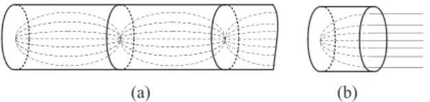
RADIENT index lenses such as Luneburg and half Maxwell fish-eye lenses have been widely used to focus the radiation of antennas. Their broadband behavior, ability to form multiple beams (especially for the Luneburg lens) and reasonable weight (as the frequency increases) make them suitable for a host of applications [1]–[3].This letter focuses on a gradient index lens that has, despite its many merits, not been exhaustively reported in the literature: the Mikaelian lens [4], [5]. In 1951, Prof. Mikaelian proposed a self-focusing cylindrical dielectric waveguide represented in Fig. 1(a). In this medium, the refractive index decreases from the center to the outer of the cylinder. Inside this waveguide, all ray paths have the same length which in terms of wave theory means that all the waveguide modes have the same velocity of propagation. This device is now well known as an optical fiber. It is easy to see that a section of such self-focusing waveguide is a self-focusing lens as drawn in Fig. 1(b).
The main intrinsic differences of the Mikaelian lens with
(a) (b)
Fig. 1. Ray tracing inside (a) a self-focusing waveguide and (b) a section of this waveguide that is a focusing lens known as Mikaelian lens.
respect to the well known Luneburg and half Maxwell fish-eye lenses are the following:
Manuscript received xx, 2014; revised xx, xx.
J. Bor, B. Fuchs, O. Lafond and M. Himdi are with the University of Rennes 1 / IETR, Rennes, France. (e-mail: {jonathan.bor;benjamin.fuchs;olivier.lafond;mohamed.himdi}@univ-rennes1.fr)
- the shape in contact to the primary source, i.e. the base of the cylinder, is flat (as opposed to spherical) which allows an easy integration with a primary source,
- the refractive index distribution has an axial symmetry (as opposed to spherical) which may be more simple to manufacture.
The crucial issue with gradient index lenses is the manufac-turing complexity. For that purpose, the innovative technique recently introduced and described in [6]–[8], is employed to manufacture a Mikaelian lens. The idea is to change the foam density in order to create the desired refractive index law. To our best knowledge, Mikaelian lens antennas have not been previously investigated in the microwave frequency range. Therefore, the aim is here to assess its focusing properties both numerically and experimentally by comparisons with the well known Luneburg lenses.
The letter is organized as follows. The theoretical properties of the Mikaelian lens are first presented. The different ways to manufacture it are briefly reviewed and a foam based technique to create the gradient index is described. The focusing performances of the Mikaelian lens are investigated and compared to the Luneburg lens ones in Section III where experimental results of the Mikaelian lens antenna are also shown. Conclusions are drawn in Section IV.
II. THEORETICALPROPERTIES ANDMANUFACTURING
TECHNIQUES OF THEMIKAELIANLENS
The optical and electromagnetic characteristics of the Mikaelian lens are detailed, the ways to manufacture such gradient index lens are reviewed and an innovative foam based technique is described.
A. Theoretical Properties of Mikaelian Lenses
The Mikaelian lens is a cylindrical lens of thickness T and radius R (see Fig. 2(a)). Its refractive index varies with the radial distance r according to the following equation:
n(r) = n(0)
cosh(π
2Tr
), with 0 ≤ r ≤ R (1) where n(0) is the refractive index along the cylinder axis. This lens is also called “hyperbolic cosine lens” in [9] because of its refractive index distribution or “constant thickness Luneburg lens” in [10] since the thickness of the lens (the height of the cylinder) is fixed contrary to the classical cylindrical Luneburg lens used for 2D focusing.
It is important to note that the ratio T /R has a direct impact on the refractive index dynamic. As plotted in Fig. 4, the thicker
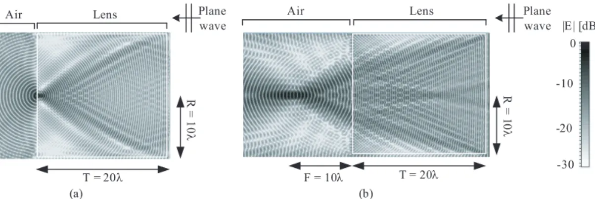
T = 20λ R = 1 0 λ T = 20λ R = 1 0 λ F = 10λ (a) (b) 0 -30 -10 -20 |E| [dB] wave wave
Fig. 3. Near electric field mappings computed by CST Microwave Studio of a plane wave impinging on (a) a Mikaelian lens and (b) a generalized Mikaelian lens. The white square shows the location of the lens.
r R 0 z (a) r R z (b) F T T r1 γ
Fig. 2. Geometrical optics ray tracing inside (a) a Mikaelian lens and (b) a generalized Mikaelian lens with the associated notations.
the lens w.r.t. its radius, the smaller the refractive index (and therefore permittivity) variation. Indeed, the ray path length differences are then less important. For a thin lens (T = R), the permittivity inside the dielectric varies from a factor 1 to more than 5 whereas for a thick lens (T = 5R), it goes only from 1 to 1.11.
Regarding the properties of the lens, geometrical optics
0 0.2 0.4 0.6 0.8 1 0.2 0.4 0.6 0.8 1 εr(r) / εr(0) normalized radius r/R T=1 R T=2 R T=5 R
Fig. 4. Relative permittivity distribution of a dielectric Mikaelian lens as a function of the normalized radius: influence of of the ratio thickness over radius of the lens T /R.
predicts that the Mikaelian lens transforms a point source into a beam of parallel rays as illustrated in Fig. 1(a). The near field mapping of Fig. 3(a) shows that a plane wave impinging
on one side of the cylinder is focused on a point.
The behavior of the lens can be adjusted by modifying the refraction index distribution. To have a focal point at a given distance F from the lens, the law of the so-called generalized Mikaelian (given in [5]) is:
n(r) = n(0)T− F (1/ cos γ − 1) T cosh(2Tπ (r− r1) ) (2) where π 2T(r− r1) = atanh ( T sin γ n(0)T− F (1/ cos γ − 1) ) .
The angle γ and the radial distance r1are defined in Fig. 2(a).
The near field mapping of a plane wave impinging on an ideal generalized Mikaelian lens with F = R = T /2 in Fig. 3(b) illustrates this focusing property. Note that the refraction index distribution (2) is very close to the one of the Kelleher lens [11].
B. Gradient Index Manufacturing
Traditional gradient index lenses have been fabricated using homogeneous dielectric shells to approximate by steps the continuous refractive index distribution [12]. In [13], the dielectric distribution of a planar Luneburg lens is achieved by varying the thickness of a dielectric between parallel plate waveguide working in TE10 mode. The desired permittivity
profile of Luneburg lenses can also be obtained by controlling the hole density in a dielectric as done with Teflon in [14]. All these techniques are expensive in terms of fabrication time and money.
More recently, printed planar Luneburg lenses have been pro-posed. The refractive index variation is performed by etching holes on a printed circuit board in [15]. In [16], the refractive of the Luneburg lens is controlled through a combination of meandering crossed microstrip lines and varying their widths. Finally, a planar Luneburg lens has been realized using a variable printed metasurface in [17]. The desired refractive index is obtained by modulating the surface impedance inside a parallel-plate structure.
Recently, an ingenious technological process has been devel-oped to control the permittivity of foam materials [6], [7]. Foam is composed of a core material into which gas is injected making its permittivity typically close to unity. By changing
the ratio between the core material and the gas, i.e. by pressing more or less the foam, it is possible to control up to a certain extent the permittivity of the foam. This permittivity can in principle range from the initial foam permittivity to the one of the core material composing the foam. More details on the pressing process and the relation between the foam density and its permittivity are given in [7]. This process is a cheap way to easily manufacture very lightweight gradient index lenses. It has already been successfully implemented for Luneburg lenses [8] and is here applied to Mikaelian lenses.
III. NUMERICALPERFORMANCES ANDEXPERIMENTAL
VALIDATIONS INMILLIMETERWAVES
The radiation performances of Mikaelian lens are investi-gated and compared numerically and experimentally to those of Luneburg lenses. The 3D full wave commercial software CST Microwave Studio is used to compute the radiation characteristics of the lens antennas.
A. Focusing Performances
The directivity and aperture efficiency of ideal Mikaelian and Luneburg lenses are compared for various lens diameters in Fig. 5. Let us recall that the aperture efficiency is the ratio between the directivity of the lens antenna and the one of a constant field circular aperture of the same diameter. Both lenses are composed of 20 homogeneous dielectric shells to approximate the ideal continuous gradient index. The Mikalian lens has a central relative permittivity ϵr(0) of 2 and a
thickness T equal to 2R. The lenses are fed by a circular open ended waveguide of diameter 2.85 mm whose directivity alone is 8.1 dB.
These radiation characteristics show that, roughly speaking, both lenses behaves similarly. It seems that the Luneburg lens antennas performs better than the Mikaelian lens for large diameters (above 20 λ) whereas the opposite happens for small diameter (below 15 λ). However, caution must be taken when interpreting these results since the directivity and consequently the aperture efficiency are relatively sensitive to the position of the antenna with respect to the lens.
10 15 20 25 20 30 40 Directivity [dB] 10 15 20 25 70 80 90 100 15 20 25 Aperture efficiency [%] lens diameter [λ]
Fig. 5. Directivity and aperture efficiency as a function of the lens diameter for the ideal Mikaelian (solid line) and Luneburg (dashed line) lens fed by a circular waveguide.
TABLE I
CHARACTERISTICS OF THE MANUFACTUREDMIKAELIAN LENS
ri[mm] εi tan δi 2.8 2.16 0.017 5.6 2.14 0.016 8.4 2.09 0.016 11.2 2.01 0.015 14 1.92 0.015 16.8 1.81 0.014 19.6 1.69 0.013 22.4 1.56 0.012 25.2 1.43 0.009 28 1.30 0.008 B. Experimental Results
A foam based planar Mikaelian lens of thickness T = 2R =56 mm and height 3 mm has been manufactured. The lens diameter (or rather width for the planar version) is equal to 11.2 λ at 60 GHz. The lens is made from the foam material Airex PXc245 [18]. Without being pressed the properties of the foam are at 60 GHz: ϵr = 1.31 and tan δ = 0.008. The
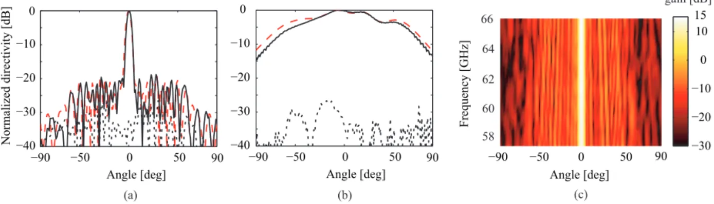
permittivity law of the Mikaelian lens is approximated by 10 values given in Table I which correspond to the 10 heights before pressing shown in Fig. 6(a). The lens is fed by a WR15 open ended waveguide operating in the V-band (see Fig. 6(b)). The measured and simulated radiation patterns of the Mikaelian lens antenna at 60 GHz are plotted in Fig. 7(a,b). A fairly good agreement is obtained between simulation and measurements for both E- and H-plane. In the H-plane, the measured half power beamwidth is equal to 4.4 ˚ , sidelobes are below 19 dB and the cross polarization level is below -25 dB. Note that the asymmetry in the E-plane is due to the non-symmetry of the mechanical support. The gain patterns in the H-plane are plotted as a function of the frequency in Fig. 7(c). They confirm the expected broadband behavior of the lens antenna and show that the Mikaelian permittivity law is properly respected.
The measured gain and loss efficiency (gain over directivity) are plotted as a function of the frequency in Fig. 8. The gain increases from about 14 dB at 57 GHz to 15 dB at 66 GHz whereas the loss efficiency is between 35 and 39%. This low value of the loss efficiency are due to the relatively high losses of the foam especially when pressed (see the loss tangent in Table I).
IV. CONCLUSION
An investigation on the Mikaelian lens antennas in the mil-limeter wave region has been presented. The design principles and theoretical properties of this cylindrical gradient index lens are recalled. A novel way to create a cheap and lightweight permittivity distribution from foam is applied to manufacture the lens. The focusing properties of Mikaelian lenses are similar to the Luneburg lens ones as shown numerically. The experimental results in the V-band validate the numerical sim-ulations and the interest of the foam technique. Although the Mikaelian lens does not present the same ability as Luneburg lenses to form multiple beams, its cylindrical shape makes it very attractive for integrated designs.
(a) (b) (c)
Fig. 6. Pictures of the Mikaelian lens: (a) before being pressed and (b) pressed inside its mechanical support including the feeding waveguide. (c) Full lens antenna system. −50 0 50 −40 −30 −20 −10 0 Angle [deg] −50 0 50 −40 −30 −20 −10 0 Angle [deg] Normalized directivity [dB] −90 90 −90 90 (a) (b) (c) Angle [deg] −50 0 50 −90 90 Frequency [GHz] 66 64 62 60 58 −30 −20 −10 0 10 15 gain [dB]
Fig. 7. Radiation performances of the Mikaelian lens antenna. Normalized far field pattern at 60 GHz in the (a) H- and (b) E-planes: measurements (solid line), simulation (dashed line). (c) Measured gain as a function of the frequency.
58 60 62 64 66 14 15 16 30 35 40 Measured gain [dB] Frequency [GHz] Loss ef ficiency [%]
Fig. 8. Measured gain and loss efficiency of the Mikaelian lens antenna as a function of the frequency.
ACKNOWLEDGMENT
The authors thank Herv´e Merlet and Dr. Philippe Le Bars for fruitful discussions.
REFERENCES
[1] H. Mosallaei and Y. Rahmat-Samii, “Nonuniform Luneburg and 2-shell lens antennas: Radiation characteristics and design optimization,” IEEE Trans. Antennas Propag., vol. 49, no. 1, pp. 60-69, Jan. 2001. [2] Y.-J. Park and W. Wiesbeck, “Offset cylindrical reflector antenna fed
by a parallel-plate Luneburg lens for automotive radar applications in millimeter-wave,” IEEE Trans. Antennas Propag., vol. 51, no. 9, pp. 2481-2483, Sep. 2003.
[3] B. Fuchs, O. Lafond, S. Rondineau, and M. Himdi, “Design and characterization of half maxwell fish-eye lens antennas in millimeter waves,” IEEE Trans. Microwave Theory and Techniques, vol. 54, no. 6, pp. 2292-2300, June 2006.
[4] A.L. Mikaelian, “Application of Laminated Media for Wave Focusing,” Journal of Dokladi. Akademii Nauk, vol. LXXXI, no.4, 1951. [5] A.L. Mikaelian, “Self focusing media with variable index of refraction,”
E. Wolf, Progress in optics XVII, North Holland, 1980.
[6] H. Merlet, P. Le Bars, O. Lafond, and M. Himdi, “Manufacturing method of a dielectric material and its application to millimeter-waves beam forming antenna systems,” patent WO2013083794, June 2013. [7] J. Bor, O. Lafond, H. Merlet, P. Le Bars, and M. Himdi, “Technological
process to control the foam dielectric constant - applications to mi-crowave components and antennas,” accepted in IEEE Trans. Compon. Packag. Manuf. Technol., 2013.
[8] J. Bor, O. Lafond, H. Merlet, P. Le Bars, and M. Himdi, “Foam based Luneburg Lens Antenna at 60 GHz,” Progress in Electromagnetic Research B, vol. 44, pp. 1-7, 2014.
[9] Y.T. Lo and S.W. Lee, “Antenna Handbook: antenna theory,” vol. II, Van Nostrand Reinhold: New York, 1993, ch. 16, pp. 53.
[10] H. Jasik, “Antenna Engineering Handbook,” New York: McGraw-Hill, 1961, ch. 15, pp. 18-19.
[11] C. Goatley and C.F. Parker, “Symmetrical microwave lenses,” IRE, vol. 3, pp. 13-19, March 1955.
[12] G.D.M. Peeler and H.P. Coleman, “Microwave Stepped-Index Luneburg Lenses,” IRE Trans. Antennas Propag., vol. 6, no. 2, pp. 202-207, April 1958.
[13] G.D.M. Peeler and D. Archer, “A two-dimensional microwave Luneberg lens,” IRE Trans. Antennas Propag., vol. 1, no. 1, pp. 12-23, Jul. 1953. [14] S. Rondineau, M. Himdi, and J. Sorieux, “A sliced spherical Luneburg lens,” IEEE Antennas Wireless Propag. Lett., vol. 2, pp. 163-166, 2003. [15] L. Xue and V. F. Fusco, “Printed holey plate Luneburg lens,” Microw.
Opt. Technol. Lett., vol. 50, no. 2, pp. 378-380, Dec. 2007.
[16] C. Pfeiffer and A. Grbic, “A Printed, Broadband Luneburg Lens An-tenna,” IEEE Trans. Antennas Propag., vol. 58, no. 9, pp. 3055-3059, Sep. 2010.
[17] M. Bosiljevac, M. Casaletti, F. Caminita, Z. Sipus and S. Maci, “Non-Uniform Metasurface Luneburg Lens Antenna Design,” IEEE Trans. Antennas Propag., vol. 60, no. 9, pp. 4065-4073, Sep. 2012.