COIM: An Object-Process Based Method
for Analyzing Architectures of Complex,
Interconnected, Large-Scale Socio-Technical Systems
The MIT Faculty has made this article openly available. Please share
how this access benefits you. Your story matters.
Citation Osorio, Carlos A., Dov Dori, and Joseph Sussman. “COIM: An Object-process Based Method for Analyzing Architectures of Complex, Interconnected, Large-scale Socio-technical Systems.” Systems Engineering 14.4 (2011): 364–382. CrossRef. Web.
As Published http://dx.doi.org/10.1002/sys.20185
Publisher John Wiley & Sons, Inc.
Version Author's final manuscript
Citable link http://hdl.handle.net/1721.1/78281
Terms of Use Creative Commons Attribution-Noncommercial-Share Alike 3.0
M
Maassssaacchhuusseettttss IInnssttiittuuttee ooff T
Teecchhnnoollooggyy
E
Ennggiinneeeerriinngg SSyysstteem
mss D
Diivviissiioonn
Working Paper Series
ESD-WP-2009-12
COIM: A
N
O
BJECT
-P
ROCESS
B
ASED
M
ETHOD FOR
A
NALYZING
A
RCHITECTURES OF
C
OMPLEX
,
I
NTERCONNECTED
, L
ARGE
-S
CALE
S
OCIO
-T
ECHNICAL
S
YSTEMS
Carlos A. Osorio
1, Dov Dori
2, Joseph Sussman
31Universidad Adolfo Ibáñez,
Santiago, Chile [email protected]
2Technion, Israel Institute of Technology,
Haifa, Isreal, and Massachusetts Institute of Technology, Cambridge, MA [email protected]
3Massachusetts Institute of Technology,
Cambridge, MA [email protected]
COIM: An Object-Process Based Method for Analyzing
Architectures of Complex, Interconnected, Large-Scale
Socio-Technical Systems
Carlos A. Osorio1 ([email protected]), Universidad Adolfo Ibáñez (Santiago, CHILE)
Dov Dori ([email protected]), Technion, Israel Institute of Technology (Haifa, ISRAEL), and
Massachusetts Institute of Technology (Cambridge, MA)
Joseph Sussman ([email protected]), Massachusetts Institute of Technology,
(Cambridge, MA)
Version 1.6, date August 8th, 2009.
Abstract
There is growing evidence of the relevance of human behavioral factors in the success of development of new products, processes and services. The evidence is even clearer when the forces affecting the development and evolution of long-lived, large, and open complex socio-technical systems are researched. Methods that study the architecture of such types of systems can help scholars and practitioners to better understand, manage, and develop socio-technical systems. We propose an approach and a method to address these needs that is grounded in the theory of systems architecture and builds on the strengths of Object Process Methodology (OPM) and the process for representing Complex Large-scale Interconnected Open Socio-technical (CLIOS) systems. We do so by integrating these methods into the CLIOS-OPM Integrated Method (COIM). COIM is conducive to studying a system’s architecture and its evolution, as it is enhanced by a set of qualitative methods for answering questions about the reasons (why) and process (how) of change in human-made systems over time.
Keywords: system architecture, evolution, legacy, Object Process Methodology (OPM), complex large-scale interconnected open socio-technical system (CLIOS).
1 The original research for this article was generously supported by MIT Communications Futures
Program (CFP), its industry sponsors, and NSF grant #EIA-0306723. The opinions and conclusions of this report, however, represent my views only and do not imply any endorsement by the National Science Foundation, CFP, or its sponsors.
1. Introduction and Research Objectives
This paper is motivated by an effort to study and model the forces affecting the development and evolution of long-lived, large, and open complex socio-technical systems, building on research outcomes of scholars who have effectively worked in this area.
Osorio (2007) focused on studying the architectural evolution of a specific type of long-lived socio-technical systems, namely municipal electric utilities (MEUs). In doing so, he encountered limitations on the theory and available methods and processes for answering his research questions, as there was no single satisfactory method for studying the evolution of the architecture of MEUs and explaining their diversification into broadband provision. Since this evolution was contrary to predictions made by scholars and practitioners as to how and why this would happen, a new way to study and understand this evolution became necessary.
Beyond the particular interest in understanding the phenomena underlying the evolution of MEUs into broadband providers, there is a more general need to understand the underlying factors affecting the architectural evolution of complex, interconnected socio-technical systems. This need is highlighted when we study long-lived, large, and complex socio-technical systems that are open to the influences of social actors or have significant impact on society. Some examples are networks of critical infrastructure, such as transportation, electric power, and telecommunication systems, aircrafts and spacecrafts, such as the B52 and the International Space Shuttle, and software systems, such as SAP Enterprise Resource Planning, or Chile´s nationwide Government Procurement Online System.
The original architecture, design, and implementation of systems of this type are normally carried out through careful study and documentation of the functional, structural, and procedural aspects of the system under development. However, throughout the lifetime of such systems, humans change them in attempts to enhance their performance, maintain some or all of their components or subsystems, update some of their underlying technologies, and adjust their structure or functions to the changing needs of varying environments. A recurrent problem with these changes is that they are rarely documented, and even if they are, the documentation is often inaccessible to the numerous architects and designers involved in such changes over timeframes that can last many decades and often transcend the work lifespan of the involved individuals.
Improving this state of affairs requires adequate tools for studying and representing the architecture of this type of systems. Building on prior research, this paper proposes COIM—CLIOS-OPM Integrated Method—as an integrated approach, method, and notation for representing and studying architectures of complex, large-scale interconnected socio-technical systems and their evolution over time.
While no single approach can serve all purposes, a combination of methods under a guiding theory could facilitate the study of the architecture of socio-technical systems. We base our analysis on the theory of system architecture,
which provides a useful overarching framework for understanding the various factors influencing the overall form, function, and concept of a system’s architecture.
We review the literature on systems architecture and system representation, with special focus on methods, strategies, and processes of representing the structure and behavior of systems. Based on the guiding theory of system architecture, COIM is an integrated methodology that builds on the representation stage of the Complex Large-scale Interconnected Open Socio-technical (CLIOS) Process and Object Process Methodology (OPM).
When appropriate and necessary, we illustrate COIM with examples from our previous research on the diversification of municipal electric utilities into broadband services, intelligent transportation systems, and others.
2. Literature Review and Contributions to Theory
System architecting is a developing field of study (Whitney, Crawley et al. 2004). What some have called an “art” (Rechtin and Maier 2000) is increasingly gaining characteristics of science and engineering. Despite these developments, the question of how to study the architecture of large-scale socio-economic systems and their evolution has remained open. Necessary steps in our research are to understand (i) what do we mean by system architecture, (ii) what evolution a system's architecture can undergo, and (iii) what frameworks might be useful and how can they effectively be combined to represent the architecture and its evolution.
What is System Architecture?
Many disciplines in engineering and management sciences provide their own definitions for system architecture. Computer science has been an important source of contributions to the study of the architecture of complex systems. Blaaw (1997) defined computer architecture as “the minimal set of properties that determine what programs will run and what results they will produce.” It is thus concerned with the “functional appearance” of the computer, or “what should it do.” In Blaaw's view, the structure is not part of the architecture; rather it corresponds to different domains of computer design: implementation (logical structure) and realization (physical structure). In this perspective, the nature of computer architecture is no different from that of language or software architecture, ranging from microcode to application. Consequently, Blaaw defined computer architecture as the outcome of the design of a “programming language when expressions are costly”.
Also from the field of computer science, (Black 1989) presented a view for analyzing network architectures and protocols. For Black, network architecture is the definition of “what things exist” in a network, “how they operate” (protocols) and “what form they take” (topology). A common feature of the different network architectures analyzed by Black is the decoupling (Suh 1998) or orthogonality (Blaaw 1997) between major functions arranged in “layers”. These layers provide (i) a decomposition into logical subsystems, (ii) standard interfaces among them,
(iii) functional symmetry across nodes (or peer elements), and (iv) command and control.
In layered architecture, each layer operates independently and interacts with others via a set of protocols. This idea underlies each of the network architectures that (Black 1989) studied in his work: (i) Open Systems Interconnection (OSI), (ii) U.S. Government Open Systems Interconnection Profile (GOSIP), (iii) Systems Network Architecture (SNA), (iv) Digital Network Architecture (DECnet), and (v) the Defense Data Network (DDN). Interestingly, all these networks presented the same underlying concept of layered architecture described by Black.
Hans van Vliet (2001) presented the role of architecture in software development by identifying and characterizing different architectural styles and different forces affecting architecture. His focus was on how to identify and describe different software architectures: shared data, abstract data type, implicit evocation, and pipe-and-filter. He proposed that software architecture has three major objectives: (i) communicating among stakeholders, (ii) capturing early design decisions (legacy and compatibility with early versions), and (iii) transferring and reusing the system as the basis for a product family (Meyer and Utterback 1993) by providing access to common code.
In the context of information systems, the Open Group Architectural Framework (TOG 2001) has defined architecture as “a set of elements (sometimes called building blocks) depicted in an architectural model, and a specification of how these elements are connected to meet the overall requirements of an information system.” This definition requires that connections among elements, which is a structural aspect of the architecture, be specified in a model. Indeed, model-based systems engineering is an emerging area
From the literature of product development, Ulrich (1995) defined architecture as the scheme by which function is allocated to physical components, and argued for its importance in manufacturing. He stated that architecture is a key driver of
performance and managerial decision-making. More importantly, however, he
argued that architecture is specifically relevant to product change, variety, and performance, component standardization and managing the product development process. Ulrich argued that architecture is central to the change of products along their lifetime, across generations, and within a company’s variety of products. He suggested that product variety results from flexibility in architecture rather than from core capabilities (e.g., a factory’s equipment). Ulrich proposed product variety as a function of the flexibility in product architecture, component processes, and standardization.
Finally, similarly to Ulrich (1995), Crawley and Weigel (2004) proposed that the “architecture” of a technical system is defined as the way in which its concept matches its form to its function. Recent work stating various architectural "views" provides additional insights into this area (Rhodes, Ross et al. 2009).
We can find parallels among many of the works discussed in this section by defining architecture in terms of form, function and concept (Crawley and Weigel 2004). From the perspective of Black (1989), the protocols, topology and “what things exist” can correspond to function, form, and concept. We can also draw
analogy between these ideas and the terms of Ulrich (1995) scheme (concept),
function (function) and physical components (form).
Dori (2002, p. 263) defined system architecture as follows: “System architecture is the overall system’s structure-behavior combination, which enables it to attain its function while embodying the architect's concept.” This definition combines the elements of concept—how the architect envisions the solution of the problem of combining structural elements and their behavior in a way that enables the system to function as expected, thereby providing value to its beneficiaries.
Table 1 summarizes the various definitions of system architecture from the surveyed authors along with the relationships between form, function, concept, and behavior.
Table 1: Summary of System Architecture Definitions Definition of System Architecture Function defined in terms of Concept defined in terms of Form defined in terms of Source
“the minimal set of properties that determine what programs will run and what results they will produce” Architecture as the functional appearance of the computer Not explicit
Structure is not part of the architecture, but rather falls into a design domain
(Blaaw 1997)
“what things exist” in a network, “how they operate” and “what form they take”
The effect created by network components, topology and protocols, decoupled by layers Network topology, Network components are the basis of form in a network, and protocols drive their behavior
(Black 1989)
(i) a vehicle for communication among stakeholders, (ii)
capturing early design decisions, and (iii) providing a basis for transferring and reusing parts of the system. Overall desired performance of a software Understood as different architecture styles Code, which is affected by external forces (van Vliet 2001)
“a set of elements… depicted in an architectural model, and a specification of how these elements are connected to meet the overall requirements of an information system” “Overall requirements of an information system” Specification on how the elements are connected Elements on a model (TOG 2001)
“scheme by which function is allocated to physical components” The function of a product Scheme Physical components (Ulrich 1995) “the way in which a concept
matches form to function”
A systemʼs Externally delivered function Overall systemʼs concept Form (Crawley and Weigel 2004) “the overall systemʼs
structure-behavior combination, which enables it to attain its function while embodying the architect's concept” Overall systemʼs function A particular architecting concept Structure-behavior (Dori 2002)
”conceptually design, evaluate and select a preferred structure for a future state enterprise to
The enterpriseʼs value proposition and desired A particular concept of design, The preferred structure of a future state enterprise Nightingale and Rhodes
realize its value proposition and desired behaviors” behavior evaluation and selection (2009) Proposed Definition:
A systemʼs architecture is the embodiment of a concept for achieving the desired systemʼs function in terms of its form, i.e., its structure-behavior combination. A desired system function A particular architecting concept Form as a structure-behavior combination This paper
If we define “form” or “physical components” as “structure-behavior combination”, then the definitions of Black (1989), Ulrich (1995), Dori (2002), The Open Group (2001), and Crawley and Weigel (2004) coincide, expressing the same idea, which we state as follows:
A system’s architecture is the embodiment of a concept for achieving the desired system’s function in terms of its form, i.e., structure-behavior combination.
This definition is valid for architecture of any man-made system, from architecture of instruments and buildings, through software systems, to complex socio-economic engineering systems.
A useful distinction can be made between intended and emergent architecture. Intended architecture is a result of an orderly architecting process, which accounts for requirements and weighs in alternatives before committing to a specific architecture—the intended one. Emergent architecture is a result of natural or social evolution over long periods of time. Examples of intended architectures are those of a jet aircraft or a multi-core processor. Examples of emergent architectures are those of a living organism (Jacob 1977), or a city.
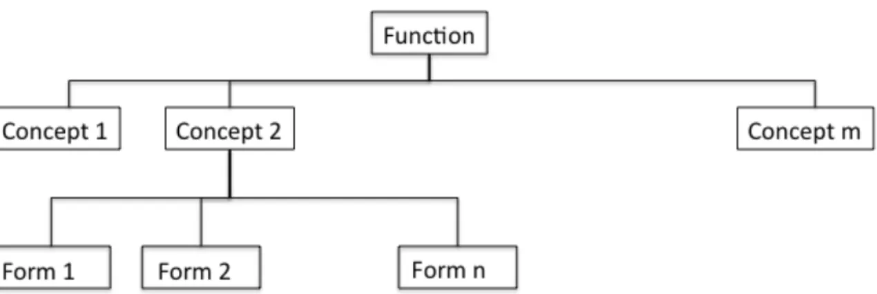
The difference between architecture and design is subtle. While architectures could be defined at higher hierarchical levels of abstraction, the different designs based on an underlying architecture could be defined at lower hierarchical levels. The BMW 3 Series, for instance, is defined as an entry-level luxury car. There have been 90 different models throughout this product’s lifetime, which can be grouped into five differentiable types of vehicles based on the same platform: (i) the 3 series BMW E21 (1975-1983), BMW E30 (1984-1994), BMW E36 (1992-1998), BMW E46 (1999-2006), (ii) BMW E90 (2005- ) 3 Series Sedan, (iii) BMW E91 (2006- ) 3 Series Wagon, (iv) BMW E92 (2007- ) 3 Series Coupé, and (v) BMW E93 (2007- ) 3 Series Convertible. The general idea is illustrated in the tree in Figure 1: Each architecture is the distinct combination of Function-Concept-Form nodes that is a path in the tree. Accordingly, Figure 1 depicts three distinct architectures: (1) Function – Concept 2 – Form 1, (2) Function – Concept 2 – Form 2, and (3) Function – Concept 2 – Form 3.
Figure 1: Different architectures of the same system, fulfilling the same function
Our working definition of a system’s architecture, as presented in Table 1, is the way in which a concept maps the system’s form (structure-behavior combination) onto its function. A first step in the analysis of the architecture of a socio-technical system is to identify the dominant influences that affect these three major dimensions of the architecture at the highest hierarchical level.
The theory of system architecture provides a guiding framework for the analysis of the form (structure-behavior combination), function, and overall concept of a socio-technical system and its subsystems, as well as the sources of dominant upstream and downstream influences.
Dominant Upstream Influences (DUI) include the regulatory and legal environment that affects form and function, corporate and marketing strategy, the influences imposed by customers and beneficiaries through their needs, the effects of the competitive environment, the evolution and availability of technology, and other strategies and internal competences. Dominant Downstream Influences (DDI) include those arising from the design, implementation, operation, and evolution of the system.
Figure 2 shows that a system’s architecture can be affected by various factors not only during its design, construction, and first implementation, but also throughout its entire operational lifetime via changes in its form (structure, behavior, or both), function, or concept. In the case of long-lived systems, one might want to focus on the architectural evolution of a system during its operational life. For example, we wish to understand how the architecture of a MEU of interest has evolved, and how the legacy aspects of its architecture have been playing a role in shaping its current architecture.
The literature review indicates that the theory of system architecture is not sufficient in that it cannot answer questions of this type. This is the current state of affairs because (i) system architecture theory is still not yet sufficiently developed, (ii) system architecture provides guidelines for system decomposition, but it does not offer methods for system representation, and (iii) system architecture does not satisfactorily address non-technical issues that greatly impact socio-technical systems.
Adapted from Crawley and Weigel (2004)
Figure 2: Dominant Influences on System Architecture
To gain more insight into what is still missing, in the next section we discuss the evolution of a system’s architecture and methods for representing system architecture.
Evolution of System Architecture
System architecture theory is in its early stages of development. However, it can already provide a useful framework for analyzing complex socio-technical systems and studying their evolution. Using this framework requires understanding of a given system’s building blocks and its representation, how its architecture evolves, and what useful ways can be employed to represent the system.
Herbert Simon (1997) presented four principles for complex systems design, which might be useful for our purpose: homeostasis, membranes, specialization, and near-decomposability.
Homeostasis is a system’s capacity to attenuate the internal effects of contextual and
environmental changes via feedback, or balancing loops in the system dynamics jargon, thereby controlling or even reducing the system’s complexity.
Membranes insulate the system and its subsystems, and serve as mechanisms for
transporting information, material, and energy. This is the basis of a work by Pimmler and Eppinger (1994), proposing strategies for product architecture and decomposition.
Specialization refers to the diversification of complex functions, which has been
used in methods such as Axiomatic Design (Suh 1998), decomposition strategies for products (Koopman 1995), and decomposition of the design process (Eppinger, Whitney et al. 1994).
Finally, near-decomposability is the ability of a system to be decomposed into structural and dynamically stable subsystems, modules, or subunits.
These principles are different facets of the flexibility of complex systems, which enables them to adapt and perform new functions. It is this architectural flexibility that enables system evolution.
From the perspective of von Vliet (2001), the evolution of architecture is affected by the developing organization—the organization actually “creating” the system. Evolution has a cyclical relationship with its environment. Von Vliet focuses on the architecture of software, an interesting contrast to the approach of Blaaw (1997) to computer (hardware) architecture.
All the cases of computer architecture discussed by Blaaw (1997) occurred prior to 1985. Once computer and software architecture shifted towards the personal computer, and the operating system (OS) was separated from the computer, his vision of architectural evolution ceased to be applicable. Computer and OS architectures are currently distinctive, and their evolution is marked by different, yet interrelated, clockspeeds (Fine 1998). Computer architecture evolves about every other year, characterized by increasing memory and processing capacity, while software architecture evolves continually. To a great extent, this gradual software evolution is due to the constant Internet-based distribution of updates and patches.
The case of computer and OS architecture is an interesting example of architectural evolution that had initially comprised one integrated system—the hardware-software monolithic computer—and evolved into two: the hardware being the physical computer and the software—the OS and various applications. This development in the computer arena is somewhat similar to a special case of evolution with relevant implications for technology management, a case in which a second line of business emerges from internal activities or functions of a socio-technical system. Studying the relationships between the form and functions of the components of the infrastructure supporting both services—hardware and software—can shed light on such evolutions (Osorio 2007).
A key concept in this context is the system’s Externally Delivered Function (EDF), which is the system’s function at its highest hierarchical level (Crawley and Weigel 2004). Alternatively, in the terminology of OPM (Dori 2002), EDF is the system’s (only) function, whereas internal functions are called processes. We shall henceforth refer to EDF as “function.” The system's function is understood by decomposing and disaggregating it into several processes (internal functions). These are usually mutually exclusive, but comprehensively exhaustive (Pimmler and Eppinger 1994). Thus, the study of architectural system evolution includes three possible cases: (i) a change in the actual function, (ii) the emergence of a new function, and (iii) internal process changes with no change to the existing function.
The first case, change in the system's actual function, pertains to the basic form of architectural evolution. It is related to changes in processes and associated form designed to enhance the original function of the system—the reason for developing it in the first place. Sometimes, however, intended architectural evolution of a system can result in severe hindrance of its performance, as was the case with the
change from the old to the new Public Transportation System of the city of Santiago, Chile, also known as Transantiago (Pelayo 2007; Mardones 2008).
In the second case of architectural evolution, emergence of a new function, the deployment of a new function is a consequence of the many external and internal influences affecting the system (Crawley and Weigel 2004; Whitney, Crawley et al. 2004; Osorio 2007). Investigators need to focus on the engineering system as a technical system embedded in a defined policy, social, and economic context (Dodder, Sussman et al. 2005; Mostashari and Sussman 2009). In the policy context, several actors can affect the form, function, or concept of the system by various regulatory means. In the social and economic contexts, residents and businesses exhibit certain needs and demand certain services. The combined effect of changes of the various types adds uncertainty to the system, creating new design spaces (MacCormack and Verganti 2003; MacCormack 2005), many of which are not observable to the managers of the system (Osorio 2007) due to bounded rationality (Simon 1991).
The existence of regulatory effects, social and economic needs, and their effect on decision-making are central to the evolution of an organization, accounting for part of the third case of architectural evolution—internal process changes with no change to the existing function. Analysis of these regulatory, social, and economic factors can help explain why architectures of long-lived systems evolve in certain ways. These systems are of special interest, because, in most cases, their evolution is partially unintended—it has not been planned by a single architect throughout the system’s life. Rather, their architecture has resulted from a series of incremental unplanned or planned, changes by different actors. In these cases, possible paths for evolution are constrained by the legacy of the pre-existing architecture, and limited by each architect’s bounded rationality and insufficient information about the evolutionary possibilities.
The open question we face is how to represent system architecture in a way that would best cater to studying its evolution.
Decomposition and Representation of System Architecture
A useful representation of a system’s architecture has the following features: (i) It results from a strategy for decomposing, relating and representing its underlying structure (objects), behavior (processes) and design concepts, and (ii) It expresses function—the high-level goal or purpose of the system, and the main reasons and objectives for the particular system’s architecture.
Koopman (1995) proposed a framework for decomposing and representing system architecture based on structures (form), behaviors (processes, or internal functions), and goals (“desired emergent properties” or needs), creating a taxonomy that allows for comparison across different strategies. While this framework considers both technical and non-technical criteria, it is explicit in not considering technical, regulatory, and political or business influences.
Koopman’s framework is based on decomposing the design according to the three previous dimensions, which range from “pure”, when performed based on only one of them, “split”, when separating dimensions into decoupled sub-designs
and using pure decomposition in each, and “combined”, which considers two or all three dimensions at the same time. The approach departs from ad-hoc decomposition by allowing options for greater modularity. It does not, however, differentiate between the design process and the resulting artifact—the final design (Koopman 1995). This missing distinction between processes and objects is a major tenet of OPM. From the perspective of our research in representing architecture of socio-technical systems, this is a major limitation, which we relate to in the sequel to this paper focused on applications.
Suh (1998) presented Axiomatic Design as a method for designing systems in terms of minimizing the complexity arising from the interaction between functional requirements (FRs), design parameters (DPs) and process variables (PVs) for systems of fixed functional requirements. Koopman (1995), and Pimmler and Eppinger (1994) followed a similar objective.
Axiomatic Design (AD) is based on two axioms: independence among functions (Independence Axiom) and achieving the least possible information content on the design (Information Axiom). The Independence Axiom is equivalent to the
Specialization of Simon (1997). The method consists of the following steps: (i)
defining the functional requirements (FRs) for the system, which requires finding the customers’ attributes and needs, (ii) mapping FRs with physical elements in order to create design parameters (DPs) and identify process variables (PVs), (iii) testing the Independence Axiom between functions, and (iv) verifying the information content of the system.
Besides the axioms, AD is based on the hierarchies among FRs, DPs, and PVs, and the zigzagging between the functional and physical domains (FRs and DPs). Hierarchy provides policy and supervisory functions that start at the highest system level and progress to lower levels of detail, tracking up and down from the beginning point, in a process called zigzagging, which is important for the design decisions between FRs and DPs.
Pimmler and Eppinger (1994) presented a method for analyzing product design decompositions and for understanding and evaluating the requirements of system engineering. The method follows a three-step process of (i) decomposing the system into elements, (ii) documenting their interactions in terms of proximity, energy transfer, information, or of material interchange, and (iii) clustering them into “chunks”. Each type of interaction ranges from –2 (interaction must be prevented to achieve functionality) to +2 (interaction is necessary for functionality). Clustering is achieved by reordering elements around a matrix diagonal in order to reduce interaction complexity. While presenting decomposition strategies, Pimmler and Eppinger do not stipulate a representation method or process.
There is, however, a methodology that includes a language and a modeling approach that draws on the theory of systems architecture to enable representation and study of systems. There is also a process for analyzing socio technical systems. Together, they provide for representing the architecture of socio-technical systems and studying their evolution. The method, Object-Process Methodology (OPM), developed by Dori (2002), has been used for conceptual modeling and system
architecting in many domains, notably in product development, and specifically by Crawley, to represent a system’s architecture based on form, functions and concept. The process for analyzing socio technical systems was developed by Sussman’s research group at MIT (Mostashari and Sussman 2009) for analyzing Complex, Large Interconnected Open Socio-Technical (CLIOS) systems. OPM and CLIOS are explained next.
Object Process Methodology
Originally, the study of a system’s architecture has focused on technical systems, and has been supported by the use of Object Process Methodology (OPM). OPM offers a consistent method for the study of the architecture of a system. It provides operators for hierarchical decomposition, and helps identify the underlying processes that link function and form. The result is a single graphical and an equivalent textual model combining the structure and behavior of the system under scrutiny at varying levels of detail. With respect to our study, OPM is limited in that it does not specifically recognize the relevance of social, organizational, and contextual dimensions; neither does it provide a way to explicitly include them in the analysis.
OPM is a methodology that is used primarily in product design and systems engineering. In OPM, a system is defined as an object that exhibits a function, where the function is “the main intent for which [the system] was built, the purpose for which it exists, [and] the goal it serves” (Dori 2002: 251).
The major features of OPM allow for hierarchical decomposition of the system into objects, or physical elements, and processes – internal functions – in a well-defined manner at various levels of hierarchy. This is done by expressing relationships between objects and processes via structural and procedural links. Agents, in OPM terms, are human operators—individuals that make the system work. Operands are the most important objects on which processes operate in order to carry out the system’s externally delivered function.
The OPM language employs certain symbols to represent the elements (form) and processes (functions) of a system’s architecture (Dori 2002). OPM includes notation for representing states (e.g., an alarm can be on or off), and can also be used to study a system’s life cycle and evolution (Dori 2002: 289). OPM is bi-modal, expressing the system model in both graphics and text—a subset of English, called Object-Process Language (OPL), that is generated automatically on the fly if one uses OPCAT (Dori, Reinhartz-Berger et al. 2003) for OPM-based modeling.
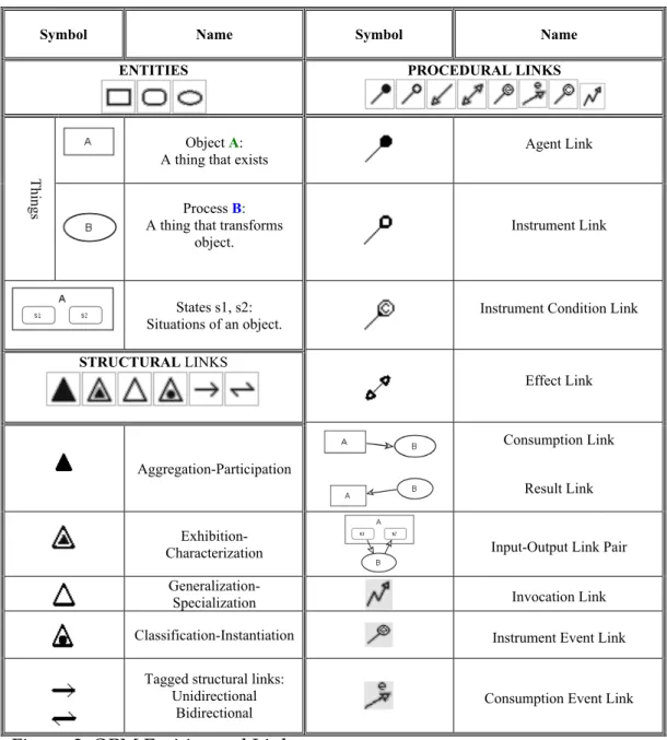
Symbols of OPM entities (objects, states, and processes), as well as of structural and procedural links and corresponding OPL sentences are shown in Figure 3 (Dori and Choder 2007).
Symbol Name Symbol Name
ENTITIES PROCEDURAL LINKS
Object A:
A thing that exists Agent Link
Things
Process B: A thing that transforms
object. Instrument Link
States s1, s2:
Situations of an object. Instrument Condition Link
STRUCTURAL LINKS Effect Link Aggregation-Participation Consumption Link Result Link Exhibition-
Characterization Input-Output Link Pair Generalization-
Specialization Invocation Link Classification-Instantiation Instrument Event Link
Tagged structural links: Unidirectional
Bidirectional Consumption Event Link
Figure 3: OPM Entities and Links
OPM has been combined with theory of system architecture for design and new product development, but it presents limitations for the analysis of complex socio-technical systems: OPM does not include the representation of direct effects of organizations or political actors on the architecture of a system.
We borrow from system architecture the focus on form, function, and concept, along with identification of needs, intent, processes and objects. The OPM modeling process starts with the examination of the way in which (i) the externally
delivered function (EDF, or simply function) is associated with the needs of
(iii) the operands and value attributes associated with the function, (iv) operators of the system, and (v) first-level decomposition of the technical system among functions and objects in at least one of the concepts for architecting the system.
We focus on the representation approach of OPM, which would enable us to understand the extent to which the system meets the needs of beneficiaries through its function. An effective way to achieve this is through hierarchical decomposition. OPM naturally represents the decomposition of the system’s function (processes) and form (objects, or components) in a top-down fashion from the most general to the most detailed abstraction levels.
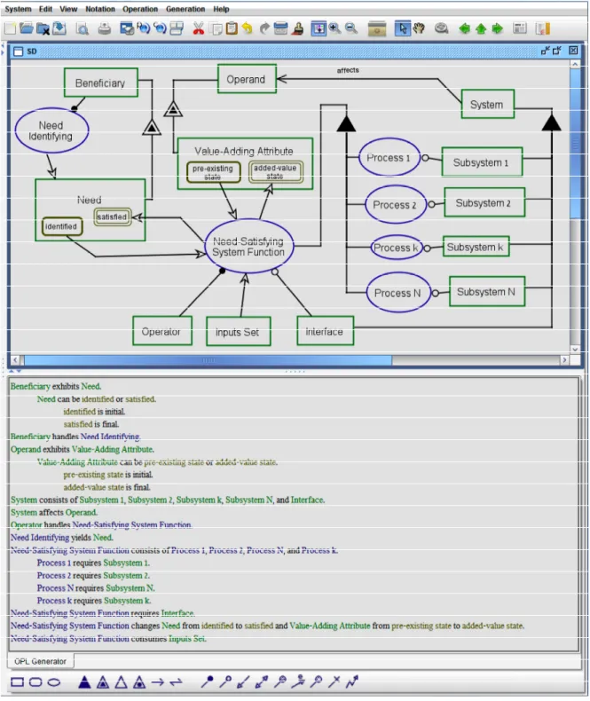
Form decomposition via aggregation-participation (whole-part) relation includes links only among units of form. Likewise, functional decomposition using the same relation includes links only among processes—functional elements. For any given level of abstraction, the form and function decompositions can be shown in a single Object-Process Diagram (OPD). Procedural links connect objects to processes, expressing the dynamic aspect of the system. This is normally done up to the third or fourth hierarchical level, which is possibly relevant for system design and development but not necessarily for our research. Figure 4 shows a typical example of how OPM is used for object-process representation of technical systems.
Figure 4: Object-Process Representation of a System’s Architecture
Depending on the architecting task at hand, it is necessary to find the “adequate” level of disaggregation in form and function that allows understanding of the underlying architecture or its evolution. The decision about the level of decomposition is based on the complexity of the system and on the analysis goals.
From this perspective, OPM has many characteristics one might want to use for studying a system’s architecture. However, for modeling socio-technical systems, OPM has two limitations:
i. It does not include any consideration of the broader social, organizational or institutional context under which the system operates, is designed, or is developed. While all these can be modeled as objects and processes, OPM does not have specific means to relate to these entities as elements that need special treatment.
ii. OPM does not explicitly consider social dimensions affecting form, function, or concept beyond the interactions of the system with its operators and consumers. Social dimensions include critical influences on a system’s architecture (DeSanctis and Poole 1994; Crawley and Weigel 2004); its organization (Orlikowski 2000), especially if it is public (Fountain 2001); and the overall strategy that governs it (Arcelus and Schaefer 1982).
To complement the strengths of OPM with a method that could offset its limitations, we have adopted the Complex, Large Interconnected Open Socio-Technical (CLIOS) Process.
The CLIOS—Complex, Large Interconnected Open Socio-Technical—Process
CLIOS is a process for analyzing Complex, Large Interconnected Open Socio-Technical systems in an iterative manner. The CLIOS Process consists of three stages: (i) representation, (ii) design, evaluation and selection of strategic alternatives, and (iii) implementation of the chosen alternatives (Mostashari and Sussman 2009) .
In this research, we focus on the Representation Stage, the objective of which is to “convey the structural relationships between the components of the CLIOS system” (Dodder, McConnell, et al. 2006). CLIOS Systems are composed of a complex Physical Domain (PD) that is nested into another complex Institutional Sphere (IS), as represented in Figure 5. The institutional sphere is formed by formal and informal organizational actors that interact with the Physical Domain. The interactions between the PD and IS create “Nested Complexity” (Dodder, McConnell, et al. 2006).
Institutional Sphere
Physical Domain
Source: Dodder, Sussman et al. (2005)
Figure 5: Illustration of Nested Complexity
The Representation Stage of the CLIOS Process provides a framework for the analysis of a socio-technical system, separating it into a physical domain nested in an Institutional Sphere. This distinction complements the analysis of dominant influences in a system’s architecture. Common drivers help identify objectives and elements that can affect system evolution by being common to two or more subsystems. The CLIOS Process, however, has two limitations: (i) it does not provide a modeling framework for representing hierarchical relationships among elements, be they elements of form (objects) or function (processes), and (ii) it does not provide a way to represent functions or processes and differentiate them from elements of form.
From the perspective of organizational theory, the concept of Nested Complexity could explain some of the dynamics among the technical and organizational dimensions of systems, as well as problems in their performance and integration. The CLIOS Process approach to studying Nested Complexity through the representation of the PD and IS is the major reason for the usefulness of CLIOS to our research.
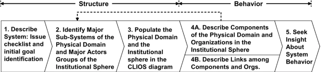
The Representation Stage of the CLIOS Process (CLIOSP-RS) follows five iterative steps, which are described below and represented in Figure 6.
1. Describe System: Issue checklist and initial goal identification 2. Identify Major Sub-Systems of the Physical Domain and Major Actors Groups of the Institutional Sphere 3. Populate the Physical Domain and the Institutional sphere in the CLIOS diagram
4A. Describe Components of the Physical Domain and Organizations in the Institutional Sphere 4B. Describe Links among Components and Orgs.
5. Seek Insight About System Behavior Structure Behavior
based on Dodder, Sussman et al. (2005)
1. System Description. The objective of this step is to describe the system, its major characteristics, goals, and the main issues at stake. The description might attempt to explain why this system is interesting, important, or generalizable. 2. Identification of major subsystems of the physical domain and major actors of the
institutional sphere. In this step, we identify the major subsystems of the CLIOS
System, their nature, and relationships among them. An important aspect here is the definition of the Institutional Sphere and the identification of actors within this sphere. Dodder, Sussman, McConnell and Mostashari (2006) have proposed one institutional sphere for their concept of “Nested Complexity”, which is created when the physical system is affected by formal or informal organizational systems.
3. Populating the physical domain and the institutional sphere. In this step (3 in Figure
6), the functions and elements of each subsystem are described in greater detail.
This is done by nesting the physical systems in the institutional sphere, layering the physical system into different subsystems and, if more detail is necessary, exploring some subsystems by expanding the analysis of some subsystems at finer granularity.
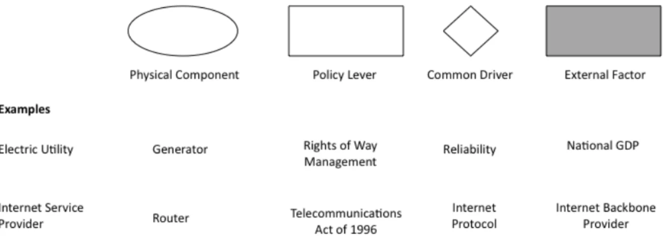
Dodder, Sussman et al. (2006) defined four types of system components (see Figure
7): (i) a physical component, represented by an oval, (ii) a policy lever, which is an
element of the technical system easily affected by actors in the IS, represented by a rectangle, (iii) a common driver, which is a “component that is shared across multiple subsystems of the physical domain”, represented by a diamond, and (iv) an external factor, which is a component that affects the system, but for practical purposes is not affected by the system, represented by a gray rectangle.
Source: prepared based on Dodder, Sussman et al. (2006)
Figure 7: Symbols of Components in the CLIOS Process
After populating the physical domain and institutional sphere, the CLIOS process follows the description of components in the physical domain and
institutions in the institutional sphere, and descriptions of links among components in the physical domain and organizations in the institutional sphere, as explained next.
4. Describing components in the physical domain and organizations in the institutional
sphere. In this step (4a in Figure 6) we add detail and understanding by
describing in detail the components on the physical domain and organizations in the institutional sphere. Detailed description results from gaining deep understanding of each component and organization’s dynamics, behavior, relevance, critical factors for performance, and insights about their relationships.
5. Identifying links among components and organizations. In this step, 4.b in Figure 6, we identify the types of relationships between components, subsystems, and the various actors. Dodder, Sussman et al. (2005) offer general guidelines for defining the properties of such links in terms of their strength, timing of influence, activity/inactivity, and, when possible, the directionality and magnitude of influence. They define three classes of links:
(i) Class 1 links – links among elements of the physical system,
(ii) Class 2 links – links between the physical system and institutional sphere, and
(iii) Class 3 links – links among components of the institutional sphere. Considering the issues discussed in previous sections and the needs of our research, we provide for representing functions and hierarchical decomposition. We need to identify functions and describe the relationships between existing and new functions of a system. The ability to represent hierarchical relations among functions is important, as it allows us to identify new functions added by design, new emergent functions, which appear unexpectedly without being explicitly designed, and changes in an existent function. This limitation of the CLIOS process can be solved by adopting ideas and notations from Object Process Methodology (OPM).
6. Gaining insights about system behavior. A major objective of CLIOS system representation is to understand its structure and behavior, at least to first order. Understanding the overall system behavior (Step 5 in Figure 6) is achieved by understanding its subsystems, components, relationships among them, and relationships with components of the IIS (internal institutional sphere) and the EIS (external institutional sphere).
The major strengths of the representation stage of the CLIOS Process are the following:
i. The CLIOS representation is explicit in considering the physical and institutional domains of socio-technical systems, allowing for analysis of the relationships and possible behavioral interactions among them. The definition of the institutional sphere is a major contribution to studying the effect of external institution-based influences in architecture. Using this representation, one can analyze how the various dominant influences on system architecture,
represented in Figure 2, affect form, concept, and function of a given socio-technical system.
ii. The physical domain in the CLIOS representation considers not only the technical subsystem of interest—for instance, the electric power infrastructure of a municipal electric utility (MEU)—but also other subsystems that explain the broader context in which a technology is embedded, e.g., the economic activity and municipal subsystems. These subsystems can have important effects on the evolution of the architecture of the technical components of a socio-technical system.
iii. The CLIOS representation includes the category of “common drivers. These common drivers identify relationships among physical components and between them and organizations in the institutional sphere.
As noted, the CLIOS representation has two main limitations with respect to achieving the objectives of our research: (i) It does not have operators that represent functions or processes as different types of elements. Since functions are one of the three main components of a system’s architecture that need to be represented, this lack is critical. (ii) It does not include an explicit way to define the hierarchy of elements or functions.
To overcome these limitations we have created a derivative method—the CLIOSP-OPM Integrated Method (COIM). COIM, presented next, builds on the strengths of OPM and the CLIOS process while offsetting their limitations.
3. An Integrated Method for Representing Architecture of
Socio-technical System
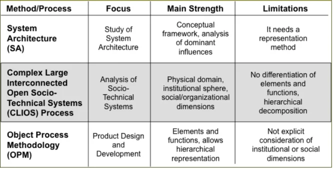
The previous sections presented the literature of system architecture, as well as the benefits and limitations of OPM and the representation stage of the CLIOS process for studying the architecture of complex socio-technical system and its evolution. Studying the architecture of this type of systems requires a combined approach. This section discusses how CLIOS and OPM are combined into the CLIOS-OPM Integrated Method (COIM), a robust analytical framework that offsets the limitations of each one of its components when used separately (See Table 2).
With systems architecture providing the theoretical framework, the combination of the CLIOS Process and OPM is the basis for our analytical framework. The simplicity of the CLIOS Process for studying large-scale socio-technical systems is enhanced with the rigor and orientation to details of OPM. An important outcome of this OPM-CLIOS Process integration is that the analysis of upstream influences2
on system architecture becomes implicit in the system representation process
2 According to Crawley and Weigel (2004), Upstream Influences in system architecture include
regulation; the organization’s strategy; needs and goals of customers and beneficiaries; competitive environment; and technologies. There are also Downstream Influences, which include the design, evolution, operation and implementation. These could be matched to the latter stages of the CLIOS Process with further development of COIM.
through the inclusion of the first stages of the CLIOS Process under a System Architecture framework. Upstream influences include regulation, the organization’s strategy, needs and goals of customers and beneficiaries, competitive environment, and technologies. We continue with a specification of COIM.
Table 2: Summary on Focus, Strength and Limitations of Approaches
Source: Osorio (2007)
COIM Terminology and Representation Operators
An important aspect of a system's representation is the extent to which it can provide insight into that system’s behavior (Sterman 2000; Dori 2002; Dodder, Sussman et al. 2005). This is particularly relevant when we wish to understand the reasons for the evolution of a system’s architecture over long periods of time, and where numerous architects and other agents and factors have been making intended and unintended changes that contributed to the current architecture. To this end, we have adopted a distinction within the CLIOS Process between the physical domain and its institutional sphere. We have also adopted OPM’s distinction between elements of form—objects and those of function—processes. The analysis is thus inspired by both the CLIOS Process and OPM.
The COIM representation operators have evolved from their original counterparts in the CLIOS Process, adding the differentiation between elements, or components, of form and function. In Figure 8, these components are depicted and exemplified using examples from the electric power industry.
Element or Component of Form Element or Component of Function Policy Lever Common Driver External Factor
E.g. transformers, transmission and distribution lines, modems, firewalls, routers, etc.
E.g. Transmission and distribution, routing, encrypting, monitoring, etc.
E.g. Coverage Reports (by FCC Form 477), Emergency Alert (by FCC Disaster Warning System), Pricing (by State PUC)
E.g. Economic Development, revenue of municipal electric utilities
E.g. United States GDP, weather Source: Osorio (2007)
Figure 8: COIM Components
• Components of form, indicated by a solid-line oval, are defined as the physical elements that comprise a system. Some examples from the electric utility domain are transformers and transmission and distribution.
• Components of function, represented by a dotted-line oval, characterize the purposes and goals of the physical elements of a system, or, equivalently, represent the functions associated with elements of form. For a distribution line, for instance, the associated function would be distribution of electric power from the distribution transformer to the customer premises.
• Policy levers, indicated by a white rectangle, are “components within the physical domain that are most directly controlled or influenced by decisions of actors…on the institutional sphere” (Dodder, McConnell et al. 2006 b). Thus, policy levers are a way by which institutional actors can affect form or function components of a subsystem in the physical domain (See Figure 10, case 3 for example).
• Common drivers, represented by a diamond, are “components that are shared across multiple and possibly all subsystems of the physical domain” (Dodder, McConnell et al. 2006). Common drivers are important influences on architecture, especially due to their influence across subsystems of the physical domain.
• External factors, represented by a shaded rectangle, are exogenous parameters that affect the system but are not affected by the system.
Component of Form Component of Function Policy Lever Common Driver A B Component of Function Component of Function Component of Form Component of Function Institutional Actor
B affects A, and A affects B: e.g. control
A yields to B, and B yields to A: e.g. Providing basic infrastructures services affects economic performance
A affects B: e.g. regulations affect system functions
B is handled by A. E.g. Energy regulation is handled by state PUC, System monitoring is handled by SCADA software
Component of Form
Component
of Function B requires A: E.g. system monitoring requires communication network Policy Lever 1 2 3 4 5 6 Source: Osorio (2007)
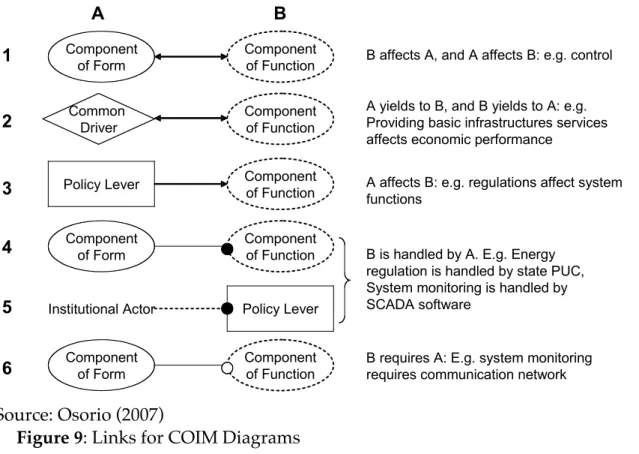
Figure 9: Links for COIM Diagrams
Based on the CLIOS Process and OPM, COIM also includes the following set of links, shown and exemplified in Figure 9.
1. Relationship of effect between components of form and function: These links are used to represent the way in which a function affects an element of form, similar to the effect link in OPM.
2. Relationship between functions and common drivers: The performance of functions can affect a common driver in the same way that a common driver can affect a function.
3. Effect of policy levers on functions: These are used to represent the way in which functions are affected by specific components in the physical domain that are controlled by actors in the institutional sphere.
4. Control of a function by a component of form: This type of relationship is used to reflect the control of functions by specific elements of form, and is represented by a solid line and black dot.
5. Control of a policy lever by an institutional actor: This is represented by a dotted line and black dot, similar to the effect link in OPM.
6. Functional requirement of a component of form: A solid line ending in a white dot represents the infrastructure requirements for performing a function.
In summary, we might have a function affecting a component of form, or a component of form affecting a function. Also, a function can affect a common driver. For instance, the provision of broadband services by municipal electric utilities affects economic development. In the same way, a common driver can affect a function or element of form. For instance, adoption of new information technologies by MEUs can affect Supervisory Control and Data Acquisition (SCADA) and Automatic Meter Reading (AMR) systems, and lead to the adoption of Internet Protocol (IP)-enabled solutions. Functions might also require a component of form, but are controlled by another element. For instance, system monitoring requires a communication network, but is controlled by the SCADA system.
Institutional actors can affect functions directly or indirectly by regulating the policy levers affecting the function. These relationships between the institutional sphere and physical domain, called “projections”, are represented by dotted lines. Functions and policy levers are controlled by components of form and actors in the institutional sphere, respectively.
The symbols described above can be used to represent the relationships among components of form, function, common drivers, policy levers, institutional actors, and external factors. We can use them to represent relationships of cause and effect (A affects B), control, or requirement among components.
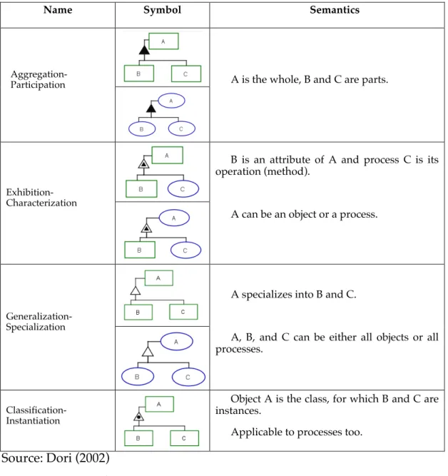
Name Symbol Semantics
Aggregation-Participation A is the whole, B and C are parts.
Exhibition- Characterization
B is an attribute of A and process C is its operation (method).
A can be an object or a process.
Generalization- Specialization
A specializes into B and C.
A, B, and C can be either all objects or all processes.
Classification-Instantiation
Object A is the class, for which B and C are instances.
Applicable to processes too. Source: Dori (2002)
Figure 10: Hierarchical Operators
Finally, we borrow a third group of operators from OPM that are especially useful for representing structural and hierarchical relationships. As Figure 10 shows, these are:
1. Representation of hierarchies: A black triangle signals the decomposition of a system into subsystems that are “mutually exclusive and comprehensively exhaustive” (MECE). The hierarchical decomposition can be performed at as many hierarchical levels as the modeler or researcher considers appropriate for the purpose of the research.
2. Representation of attributes: A black triangle inside a white triangle signals the attributes of a system, common drivers, components of form, or functions. 3. Specialization of components: A white triangle signals the characteristics of
4. Class of components: A circle inside a white triangle signals inclusion into types of classes.
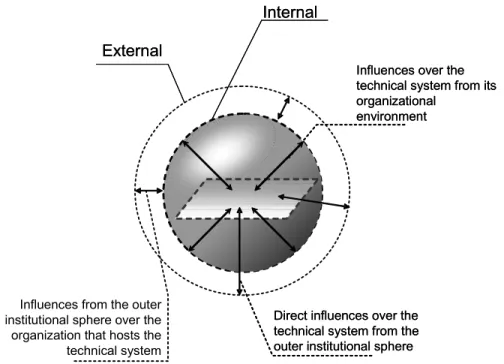
Differentiating between the External and Internal Institutional Spheres
The CLIOS Process definition of nested complexity relates to the complexity created by the embeddedness of the physical system in its surrounding organizational and institutional domain (the institutional sphere). All technical systems are directly affected by their immediate organizational environment, culture, practices, and structural embeddedness.
We examine the effect of organizations on physical system at two levels: internal and external. We thus extend the CLIOS Process by separating the institutional sphere according to the types of organizational actors and their relationships. This distinction is required due to the different nature of internal and external influences on architecture.
The internal level of the institutional sphere is formed by the immediate organizational environment of a technical system or, in other words, the organization holding and operating the technical system. This defines the internal institutional sphere (IIS). Many scholars in organizational theory and behavioral policy sciences have studied the interaction between the internal institutional sphere and the physical domain (Perrow 1986; Orlikowski and Baroudi 1991; DeSanctis and Poole 1994; Orlikowski 2000; Fountain 2001).
Several formal and informal actors outside the IIS form the external level of the institutional sphere, creating the external institutional sphere (EIS). Components of the EIS can directly or indirectly affect the technical system under study through federal or state regulation, local government rules, the practices of suppliers, or national changes in customer needs. Scholars of the history of technology, privatization, and regulation, have analyzed various ways in which public policies have affected the architecture, design, or operation of technical systems in areas such as emissions control and pollution, car safety, and electric power and telecommunications (Hughes 1983; Donahue 1989; Viscusi, Vernon et al. 1997; Newbury 1999; Laffont and Tirole 2000; Savas 2000). Theories about system architecture and product development have explained how technical systems are shaped by changes in customer needs and preferences (Rechtin and Maier 2000; Crawley and Weigel 2004; Ulrich and Eppinger 2004).
Relationships between actors in the IIS and actors in the EIS give rise to a third type of relationships that can have an indirect effect on the technical system. Several scholars have analyzed the different ways in which organizations interact in different economic and regulatory settings (Powell 1990; Powell and Smith-Doerr 1994; Podolny and Page 1998; Polenske 2004), In such interactions, the institutional sphere might impact the organization and affect the system’s performance in ways other than the direct effect on the technical system.
Figure 11 shows the differentiation between the internal and external
External External
Internal Internal
Influences from the outer institutional sphere over the organization that hosts the technical system
Direct influences over the technical system from the outer institutional sphere Direct influences over the technical system from the outer institutional sphere
Influences over the technical system from its organizational
environment Influences over the technical system from its organizational
environment
Source: Osorio (2007)
Figure 11: Illustration of Extended Notion of Nested Complexity
The influences from within and outside the organization on the technical system are of special interest, because it is necessary to show how actors from the external institutional sphere are related to components of each subsystem and to the organization that governs and directly manages the technical system. The way in which the organization is related to the main components of the physical system needs to be represented as well. To this end, COIM includes two distinctive features for representing a subsystem and the institutional sphere. First, the representation of subsystems in the physical domain includes projections from the actors on the institutional sphere affecting the subsystems. Second, the representation of the institutional sphere differentiates between IIS and EIS. It includes projections from the EIS and IIS to a summarized representation of the physical domain.
Combining Research Approaches in COIM
The study of the evolution of system architecture requires OPM to be capable of historical analysis and analysis of dominant influences in system architecture. Historical analysis allows for identifying how path dependence can affect a system’s organization (structural embeddedness and culture) and technical system (legacy of its architecture). Path dependence and legacy in architecture are especially important when studying the evolution of a system’s architecture. We therefore analyze the physical domain by investigating components of the technical infrastructure that are likely to exhibit legacy influences and can affect the evolution of the architecture of our system.
Analysis of dominant influences allows identifying and understanding the factors, sources and effects of regulatory, social, institutional, organizational and contextual changes on system architecture. In what follows, we discuss relationships between dominant influences in system architecture and the CLIOS Process at the IIS, EIS, and common drivers levels.
At the internal institutional sphere (IIS) level, an organization’s corporate and marketing strategy can affect the functions or forms of its technical infrastructure. New organizational competencies can be generated by decision making at operational and tactical levels. Other dominant influences in the IIS include internal policies or decisions about operation of the technical system, and strategies based on the identification of needs in the user base.
At the external institutional sphere (EIS) level, organizations exert three of the most important types of dominant influence in a system’s architecture: regulations, changes driven by competitive environment, and changes to the needs to be satisfied by the system. From the perspective of system architecture, the institutional actors can be divided into public and regulatory organizations, private companies providing competitive services, and other formal or informal organizations concerned about the direct or indirect effect of the system on customer needs, regulatory aspects, or other issues such as environment, labor, etc.
At the common drivers level, the dominant influences include two major drivers of the evolution of a system’s architecture: new technology and operational costs and efficiency. We consider the technical architecture of a CLIOS as a major component of its physical domain. This technical architecture can be represented as one or more subsystems. If there is more than one, then new technology and efficiency will be drivers common to all subsystems, including parts of the technical infrastructure of the system.
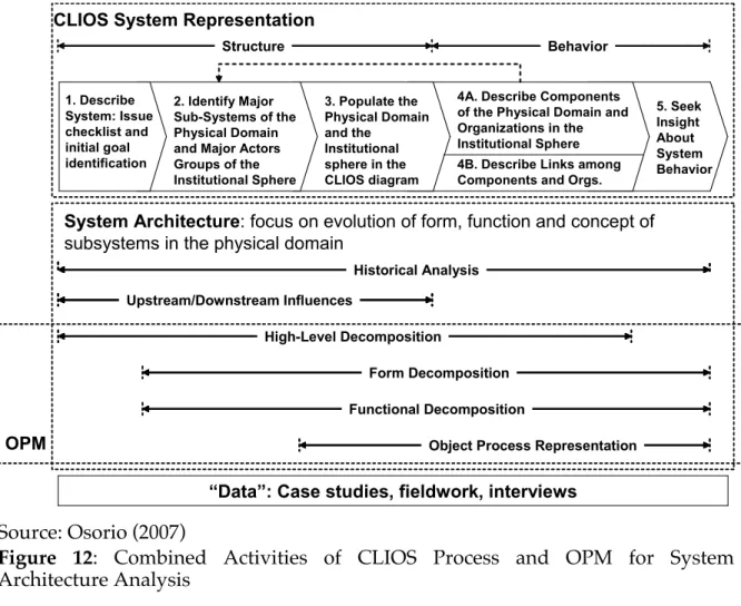
Historical analysis and analysis of dominant influences are included in the analysis of system architecture, which can also be performed using OPM. We can draw analogies between analysis of dominant influences and the CLIOS process. Thus, by integrating system architecture with OPM and the CLIOS process, we make it possible to integrate historical analysis and dominant influences into the representation process. The integration among system architecture, OPM and the representation stage of the CLIOS Process is illustrated in Figure 12.
In this integration OPM contributes with the detail and rigor from the object-process decomposition. CLIOS Process adds the analysis of the Internal and External Institutional Spheres from the Representation Stage, and System Architecture adds historical analysis, and the study of dominant influences. The purpose of this integration is creating a research method for studying the architectural evolution of a system where most of the learning comes from (i) understanding the system’s setting, (ii) understanding and identifying its sources of legacy, influences and path-dependence, and (iii) learning about the system’s evolution through the process of detailed representation of the system.