The MIT Faculty has made this article openly available.
Please share
how this access benefits you. Your story matters.
Citation
Abel, Zachary, Erik D. Demaine, Martin L. Demaine, Sarah Eisenstat,
Anna Lubiw, Andre Schulz, Diane L. Souvaine, Giovanni Viglietta,
and Andrew Winslow. "Algorithms for Designing Pop-Up Cards."
Natacha Portier and Thomas Wilke (Eds.) 30th International
Symposium on Theoretical Aspects of Computer Science (STACS
2013), February 27-March 2, 2013, Kiel, Germany (Leibniz
International Proceedings in Informatics (LIPIcs) ; Volume 20).
p.269-280.
As Published
http://dx.doi.org/10.4230/LIPIcs.STACS.2013.269
Publisher
Schloss Dagstuhl Publishing
Version
Final published version
Citable link
http://hdl.handle.net/1721.1/87552
Terms of Use
Creative Commons Attribution
Detailed Terms
http://creativecommons.org/
Zachary Abel
∗1, Erik D. Demaine
†‡2, Martin L. Demaine
2, Sarah
Eisenstat
‡2, Anna Lubiw
§3, André Schulz
¶4, Diane L. Souvaine
k5,
Giovanni Viglietta
6, and Andrew Winslow
k51 MIT Department of Mathematics, 77 Massachusetts Ave., Cambridge, MA 02139, USA, [email protected]
2 MIT Computer Science and Artificial Intelligence Laboratory, 32 Vassar St., Cambridge, MA 02139, USA, {edemaine,mdemaine,seisenst}@mit.edu
3 David R. Cheriton School of Computer Science, University of Waterloo, Waterloo, Ontario N2L 3G1, Canada, [email protected]
4 Institut für Mathematsche Logik und Grundlagenforschung, Universität Münster, [email protected]
5 Department of Computer Science, Tufts University, Medford, MA 02155, USA, {dls,awinslow}@cs.tufts.edu
6 School of Computer Science, Carleton University, Ottawa ON, Canada [email protected]
Abstract
We prove that every simple polygon can be made as a (2D) pop-up card/book that opens to any desired angle between 0 and 360◦. More precisely, given a simple polygon attached to the two walls of the open pop-up, our polynomial-time algorithm subdivides the polygon into a single-degree-of-freedom linkage structure, such that closing the pop-up flattens the linkage without collision. This result solves an open problem of Hara and Sugihara from 2009. We also show how to obtain a more efficient construction for the special case of orthogonal polygons, and how to make 3D orthogonal polyhedra, from pop-ups that open to 90◦, 180◦, 270◦, or 360◦. 1998 ACM Subject Classification I.3.5 Computational Geometry and Object Modeling Keywords and phrases geometric folding, linkages, universality
Digital Object Identifier 10.4230/LIPIcs.xxx.yyy.p
1
Introduction
Pop-up books have been entertaining children with their playful mechanics since their mass production in the 1970s. But the history of pop-ups is much older [27], and they were originally used for scientific and historical illustrations. The earliest known example of a “movable book” is Matthew Paris’s Chronica Majora (c. 1250), which uses turnable disks (volvelle) to represent a calendar and uses flaps to illustrate maps. A more recent scientific example is George Spratt’s Obstetric Tables (1850), which uses flaps to illustrate procedures for delivering babies. Dean & Sons’ Little Red Riding Hood (1850) is the first known movable book where a flat page rises into a 3D scene, though here it was actuated by pulling a string.
∗ Supported in part by an NSF Graduate Research Fellowship.
† Supported in part by NSF ODISSEI grant EFRI-1240383 and Expedition grant CCF-1138967. ‡ Supported in part by NSF grant CCF-1161626 and DARPA/AFOSR grant FA9550-12-1-0423. § Supported by the Natural Sciences and Engineering Research Council of Canada.
¶Supported in part by the German Research Foundation (DFG) under grant SCHU 2458/1-1. k Supported in part by National Science Foundation grants CCF-0830734 and CBET-0941538.
© Zachary Abel, Erik D. Demaine, Martin L. Demaine, Sarah Eisenstat, Anna Lubiw, André Schulz, Diane L. Souvaine, Giovanni Viglietta, and Andrew Winslow;
licensed under Creative Commons License BY Conference title on which this volume is based on. Editors: Billy Editor, Bill Editors; pp. 1–12
Leibniz International Proceedings in Informatics
The first known examples of self-erecting pop-ups, where the rise into 3D is actuated by opening the page, are a card promoting the Trinity Buildings in New York City (c. 1908), and S. Louis Girand’s Bookano Book (c. 1930s). Modern pop-ups have taken these principles to new heights, often employing linkage-like mechanisms to form elaborate 3D shapes and motions; some good guides for designing pop-ups are [1, 3, 5, 20]. In recent years, pop-up books have risen to an art form with such art books as Bataille’s ABC3D [2], Carter’s series of dot/spot books [4], and Pelhem’s poetic pop-up book [26]. One striking form of pop-ups is
origamic architecture, which form buildings and other geometric structures, and are usually
made by cutting a single sheet of card stock. A few examples of origamic architecture books are [7, 8, 32]; see [11] for a thorough bibliography.
Our results. This paper investigates the computational geometry of pop-ups, in particular, algorithmic design of pop-ups. We achieve three main results:
1. Any 2D n-gon (extruded orthogonally into 3D) can be popped up by opening a book to a specified angle θ with 0 < θ ≤ 360◦, using a construction of complexity O(n2). 2. Any orthogonal n-gon (extruded orthogonally into 3D) can be popped up by opening a
book to a specified angle θ ∈ {90◦, 180◦, 270◦, 360◦}, using a construction of complex-ity Θ(n).
3. Any orthogonal polyhedron can be popped up by opening a book to a specified orthogonal angle θ ∈ {90◦, 180◦, 270◦, 360◦}, using a construction of complexity O(n3).
All of our constructions use rigid flat polygonal pieces to form single-degree-of-freedom linkage structures, which uniquely and deterministically unfold from the flat state to the open state, while avoiding collision.
Related work. Our results solve an open problem of Hara and Sugihara [14], who gave an algorithmic construction for arbitrary polygons, but with no guarantees of collision avoidance (and indeed the construction sometimes requires collisions). In another result in computa-tional geometry, Uehara and Teramoto [31] proved that pop-ups with creases that can fold both mountain and valley are NP-hard to open or close.
In computer graphics, Mitani et al. [23, 24] showed how to automatically design pop-ups within a common class of 90◦ origamic architecture, in which the surface is monotone (hit only once) in the view direction. This work led to Tama Software’s Pop-Up Card Designer [30]. Li et al. [22] developed a software system for converting a given 3D model into one that fits within this class. Several other systems enable designing and simulating pop-ups by composing standard pop-up gadgets, including Glassner’s [12, 13], Popup Workshop [16, 15], Okamura and Igarashi’s [25], and Iizuka et al.’s [19].
Geometric pop-ups have also been studied for specific examples of polyhedra. The first such example is a rhombic dodecahedron of the second type [10]. Other examples include the dodecahedron [29] and other Platonic solids [17, 6, 21]. These types of pop-ups are typically not attached to pages of a book, however.
Applications. Pop-ups have potential practical applications as well. Nano and micro fabri-cation technology are well-established for patterning 2D sheets, but remain in their infancy for 3D surfaces. Pop-ups offer a way to transform patterned 2D sheets into 3D surfaces. This idea was recently explored in the context of MEMS [18], where Hui et al. manufactured a 1.8mm-tall 3D model of the UC Berkeley Campanile clock tower using pop-ups.
2
Models of Pop-Ups
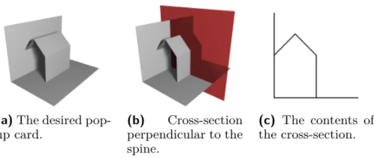
(a) The desired
pop-up card. (b) Cross-section perpendicular to the spine. (c) The contents of the cross-section.
Figure 1 Three views of a desired 3D structure, before the
creases and extra paper have been added to make it pop up. Our basic model is of a book
with planar front and back cov-ers which, when opened to a desired angle θ, pops up a 3D paper construction made from pieces of stiff paper that are folded and glued to each other and to the covers. (We will not deal with the more restrictive model of origamic architecture where one piece of paper is cut and folded but not glued.)
Given a desired 3D structure, we aim to design a book that pops up the structure by adding creases and extra pieces of paper. Adding creases may be necessary to let the structure fold up when the book is closed. Adding extra paper may be necessary to make the structure pop up into the correct shape when the book is opened.
(a) A common joint.
(b) A flap.
(c) A sliceform.
Figure 2 The three types of joints used in this paper. Until Section 5, we consider a restricted version of the problem
that arises when all fold lines and all gluing lines are parallel to the spine, as in Figure 1. In this case, a cross-section of the 3D structure in a plane perpendicular to the spine yields a 2D pop-up: the pop-up structure forms a planar linkage composed of rigid bars (line segments) connected at joints. A joint is a point where bars intersect, usually at an endpoint of at least one of the bars. We distinguish three kinds of joints:
Common joints: Two or more bars are linked at one of their endpoints. Flaps: A bar contains a joint in its interior, where an endpoint of another bar is linked. The location of the joint at the interior of the first bar is fixed.
Sliceforms: A joint (called a sliceform) can be formed by the intersec-tion X of two bars. The intersecintersec-tion point X cannot shift along
the bars, but the two bars can change their angle at X (scissors-like). Notice that we do not consider the two edges crossing if they are linked by a sliceform.
To distinguish the different joints in figures, we use a dot (•) for common joints and endpoints of edges, an empty circle (◦) for flaps, and a cross (×) for sliceforms.
Figure 3 Simulating
sliceforms. The common joint is sufficient to simulate the other joint types.
A flap can be simulated by forming a zero-area triangle among the three collinear points. A sliceform can be simulated by common joints and flaps as illustrated in Figure 3.
In the 2D case, we want to construct a linkage L with one degree of freedom that unfolds to the desired polygon P . During the folding motion we require that no bars cross, and that the order of the bars emanating from a joint is preserved. Let the vertices of
P be v1, v2, . . . , vn labelled in counter-clockwise order. The edge
incident to vi and vi+1 is named ei, and the edge between vn and
wedges bounded by the rays −−→v1v2 and −−→v1vn. The angle of the wedge containing P is called
the opening angle, and the union of the rays −−→v1v2 and −−→v1vn is called the cover. We require
L to have the following properties:
1. In one configuration of L, the boundary of L coincides with P . We call this the open
configuration. The linkage L contains the edges e1 and en of P as bars. If a joint of L
coincides with a vertex vi in the open configuration, we name it pi.
2. In one configuration of L that can be reached from the open configuration, all edges are collinear and p1is an endpoint of the union of the edges of L. This configuration is called
the closed configuration.
3. There is a unique motion that transforms the open configuration into the closed config-uration. During this motion, L is contained inside the wedge defined by the cover and the opening angle decreases continuously. We refer to this motion as the closing motion. Every configuration of L obtained during the closing motion is called an intermediate
configuration. The open configuration might have several joints that are opened 180◦. In order to specify the folding uniquely, we prescribe for every such ambiguity the way the vertex moves during the folding motion. Collinear points in the open configuration appear naturally in pop-up structures. In the real world the folding motion at these points is prescribed by the creasing of the paper.
The combinatorial complexity of a 2D pop-up is equal to the number of joints in the pop-up.
3
Orthogonal Polygon Pop-Ups
In this section, we assume the polygon P is orthogonal, i.e., every edge of P is either horizontal or vertical. Under this assumption, we show how to construct a pop-up linkage
L for the polygon P with combinatorial complexity linear in n. The techniques we use in
this section are based on a particular type of motion:
IDefinition 1. A shear is a motion of a linkage that leaves parallel edges parallel.
In Section 3.1, we explain how to construct pop-ups for polygons with opening angle 90◦, also known as 90◦ pop-ups. In Section 3.2, we extend this result to larger opening angles.
3.1
90
◦Pop-Ups
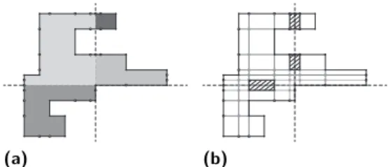
To construct 90◦pop-ups, we use a process called h-superimposing. As a first step we split
P into stripes such that (i) each stripe is an axis-aligned rectangle, (ii) the left and right
boundary edges of a stripe are a part of the boundary of P , and (iii) the union of any two stripes is not a rectangle. We obtain such a decomposition by extending all horizontal edges of P horizontally as long as they lie in P . See Figure 4a for an illustration. Two stripes are
adjacent if they (partially) share an edge.
Let L1be the linkage obtained by extending all horizontal edges as long as they lie within
P . The newly introduced degree-3 vertices become flaps. An example of this is depicted in
Figure 4b. This intermediate linkage may have more than one degree of freedom: any pair of adjacent stripes that do not share a vertical bar can shear independently. To handle this, note that for any pair of adjacent stripes, there must be at least one vertical line passing through the (strict) interior of both stripes. We call this a bracing line for the stripe pair. The subset of the line contained in the stripe pair is called a bracing segment. For each pair of adjacent stripes that do not share a vertical bar, we add a bracing segment to the linkage, creating a sliceform joint where the segment intersects with the boundary between
(a) The stripes induced by
ex-tending all edges horizontally.
(b) The intermediate linkage,
with too many degrees of free-dom.
(c) The final linkage, with bracing segments to enforce a single shear motion.
Figure 4 The result of h-superimposing an orthogonal polygon.
the stripes. See Figure 4c for an example. Let L2 be the linkage resulting from the addition
of the bracing segments.
ITheorem 1. The linkage L2 obtained by h-superimposing defines a pop-up fold for the
or-thogonal polygon P with 90◦opening angle. The motion of L2is a shear. The combinatorial
complexity of L2 is O(n).
All omitted proofs may be found in the full version of this paper.
3.2
180
◦, 270
◦, and 360
◦Pop-Ups
2 2 O A B G L R F E D M C M′ 1 1 1 1 2 1 2 1 1 1 1(a) The open configuration.
O A B G L R (b) An intermediate con-figuration.
Figure 5 The
reflec-tor gadget that helps to “reflect” two shearing mo-tions.
This section is devoted to constructing pop-up folds with larger opening angles. We reduce this problem to the 90◦ pop-up sce-nario by introducing a linkage (called a reflector gadget) that al-lows us to reflect a shear. The open configuration of the gadget is constructed as shown in Figure 5a. Figure 5b depicts an interme-diate configuration.
ILemma 1. The reflector gadget has one degree of freedom. Its closing motion has the following properties:
1. the vertical line segments in the open configuration remain vertical during the induced motion,
2. the boundary of the gadget is symmetric with respect to a line of reflection running through OM , and
3. the linkage folds to a line without introducing any crossings in an intermediate configuration.
We use the properties of the reflector to combine two 90◦ pop-ups to create a pop-up with larger opening angle. We discuss 180◦
pop-ups first. In this case both cover edges lie on a line through p1.
To guide our construction we add a bisector s of the cover edges that runs through p1. Furthermore, we add two lines parallel to s
such that the induced stripe contains s and does not contain any point of P except those lying on s. This stripe is called S. The edges that “appear” when intersecting P with the boundary of S are added to the linkage L. We “fill” each rectangle obtained by intersecting P with S with a reflector gadget. The components of
P \ S are turned into a linkage by h-superimposing as discussed in
Section 3.1, so that every component of P \ S supports a shearing
motion. The shearing motions are linked by the reflector gadgets, so the combined linkage
(a) (b)
Figure 6 A 180◦ pop-up fold constructed with the help of reflector gadgets. (a) The open configuration. (b) An intermediate configura-tion.
(a) (b)
Figure 7 (a) A polygon with opening angle
270◦. The induced connected components are drawn with different shades of grey. (b) The pop-up linkage. The reflector gadgets have to be inserted at the crossed regions.
s perform a shear and both parts of P stay on their own side, relative to s. Hence it is
impossible for L to self-intersect. Notice that we can always make the stripe S thin enough that the rectangles of P ∩ S are not “too wide” for the reflector gadgets. See Figure 6 for an example. We conclude with:
ITheorem 2. The method described above constructs a pop-up fold for the polygon P with opening angle 180◦. The combinatorial complexity of the linkage is O(n).
In order to realize 270◦ and 360◦ folds we extend the 180◦ construction as follows. We split P into pieces by cutting it along the horizontal and vertical lines through p1. We then
turn each connected component of the split polygon into a 90◦ linkage, by adding bars and joints as discussed in Theorem 1. Then each piece of the polygon will be constrained to move in a shear motion, but different pieces will not necessarily move together. To synchronize the pieces, we use reflector gadgets to connect them. To generate the space for the gadgets, we add bars that sandwich the horizontal and vertical lines through p1, thereby creating vertical
and horizontal strips in which the reflector gadgets can be placed. Because no gadgets lie inside the intersection of the vertical and horizontal strip, no two reflector gadgets interfere. Figure 7 shows an example of an 270◦fold. We conclude with the following theorem:
ITheorem 3. The method described above constructs a pop-up fold for the polygon P with opening angle 270◦ or 360◦. The combinatorial complexity of the linkage is O(n).
4
General Polygon Pop-Ups
In this section we provide a different method for constructing pop-ups of polygons. This method works for all simple P (not necessarily orthogonal), but has a higher asymptotic complexity of O(n2). Before giving the construction, we provide a key geometric lemma
about the non-crossing of nested “V-fold” linkages.
4.1
Nested V-folds
We define an outward V-fold as the single-degree-of-freedom linkage formed by a (weakly) convex quadrilateral ABCD with AB + BC = AD + DC. (This was called a V-fold in [14].) Such a linkage folds flat as the opening angle ∠BAD decreases to zero. If, in the open configuration, the angle at C is 180◦ and the angle at A is less than 180◦ (i.e. the quadrilateral is a nontrivial triangle with C on side BD), we call this linkage a flat outward
AB − BC = AD − DC has one degree of freedom and folds flat without overlap, and is
called an inward V-fold. If the angle at C is 180◦ and the angle at A is less than 180◦ it is a flat inward V-fold.
ITheorem 4. (a) Let ABCD and AB0C0D0 be flat outward V-folds on the same rays with 4BAD ⊂ 4B0AD0, where we may have B = B0 or D = D0. Then these linkages do not
cross during the closing motions. In fact, they do not touch at all, except at the closing configuration and possibly at the endpoints B = B0 or D = D0 if either equality holds.
(b) The same statement holds with “outward” replaced by “inward”.
4.2
The General Pop-Up Construction: The Method
We may now describe the construction for pop-ups of general polygons. As in Section 2, we wish to construct a one-degree-of-freedom linkage L contained in simple polygon P =
v1v2· · · vn, where P is contained in the wedge formed by rays v1v2and v1vn. We sometimes
refer to the crease point v1 as O. The opening angle θ of the original configuration, namely
the angle of polygon P at vertex O, may take any value 0 < θ ≤ 360◦.
First we discuss the general strategy and provide a linkage L1that has a pop-up motion
for polygon P but has more than one degree of freedom. Later we brace the linkage to remove the excess flexibility.
We first subdivide the wedge around O containing P by rays starting at O, where there is one such ray through each vertex of P and additional rays are inserted so that consecutive rays form acute angles. Suppose r1, . . . , rtare these rays in order around O = v1, starting
at r1 =
−−→
Ov2 and ending at rt =
−−→
Ovn. The region of the plane between rays ri and ri+1
is the ith wedge, Wi. We subdivide polygon P by these rays: any positive length segment
of a ray ri contained in P or its boundary is inserted as a single bar in linkage L1 and is
called a wall segment. Notice that edges of P may be wall segments. Also, by slight abuse of terminology, a positive length subsegment of a wall segment is also called a wall segment. Any isolated points on ri∩ P are necessarily vertices of P and are called wall points.
The rays risubdivide P into a number of triangles and quadrilaterals, called cells. Each
cell has two wall portions on consecutive rays: at least one of these is a wall segment, and the other may be a wall segment or point. A cell that has two wall segments is called an
internal cell, and those with a wall point are ear cells. Two cells are adjacent if they share a
wall segment. By adding at most one new ray for each ear cell, (and renumbering the rays as necessary), we may assume that each ear cell is adjacent to a unique interior cell.
The rays ri also subdivide the boundary of P into segments. On each such segment AB
that is not a wall segment (which implies A and B are on consecutive rays), insert a joint
C at the point that would make OACB an outward V-fold at O, i.e., C is the unique point
on AB with OA + AC = OB + BC. This linkage L1 serves our first stated purpose:
ILemma 2. The linkage L1, constructed from P by adding wall segments and extra
bound-ary vertices as described here, can be continuously folded flat without overlap.
Proof. Let φi be the angle of wedge Wi, i.e., the angle between rays ri and ri+1 at O.
Con-sider any continuous rotation of rays r1, . . . , rt around O such that all angles φ1, . . . , φt−1
decrease monotonically to 0. Let each wall portion on ray rirotate around O to stay on ray
ri, and for each boundary portion ACB of P within wedge Wi, let ACB fold outward as
would the outward V-fold OACB. Then path ACB remains inside wedge Wi throughout
the motion, and therefore does not interact with portions of P in different wedges. Further-more, by Theorem 4, the various boundary portions in wedge Wi do not touch each other
The rest of the construction shows how to add additional support to L1to turn it into a
one-degree-of-freedom linkage whose motion has the form described in the proof of Lemma 2. We cut down the freedoms of L1 in several steps, given in the next three subsections.
4.3
Constraining Wall Segments to Rotations
A C B D E F G H P Q R S
Figure 8 Rotation gadget. For two segments P Q and RS whose lines intersect at a
point O, consider the rotation gadget as illustrated in Fig-ure 8. (When we apply this below, P Q and RS will be wall segments, and O will be the crease point.) This linkage is specified as follows: AB k DE are any two segments not sharing an endpoint with P Q or RS with AB closer to O than DE; C is chosen on AB so that OA + AC = OB + BC, and the 180◦angle at C is declared to fold outward, with F on DE chosen similarly; G and H are chosen so that both
DACG and CBEH are parallelograms.
ILemma 3. The linkage illustrated in Figure 8 has one degree of freedom. If P Q and point
O are held fixed in the plane, then in the unique motion, segment RS rotates rigidly around
point O from its starting position to a closed configuration where P Q and RS are collinear.
ILemma 4. Let L2be the linkage derived from L1as follows: for every internal cell, attach
a rotator gadget inside the cell connecting (internal subintervals of) the wall segments. Then the motions of L2correspond exactly to those motions of L1where wall segments only rotate
around O, and planar motions of L1extend (uniquely) to planar motions of L2.
4.4
Synchronizing Wall Segments
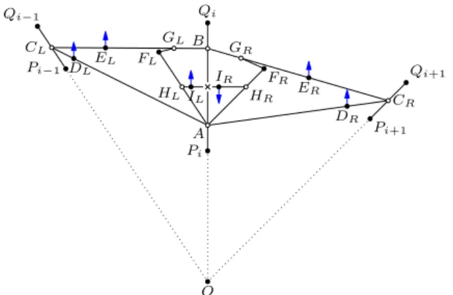
Pi−1 Qi−1 Pi Qi Pi+1 Qi+1 A B O CL DL EL FL GL HLIL CR DR ER FR GR HR IR
Figure 9 Synchronizing gadget. We next show how to synchronize the
wall segments to ensure that all wall segments originally on ray ri remain on
a single ray through O throughout any continuous motion. Let φ1, . . . , φt−1
be the initial angles of the wedges
W1, . . . , Wt−1. For an internal cell
ABCD with AB ⊂ ri and CD ⊂ ri+1,
we know that any motion of L2 rotates
AB and CD around O, and we define
the angle of the cell at any time as the angle between rays OAB and OCD.
IDefinition 2. For each 1 ≤ i ≤ t − 2, construct a linkage Mi with two
adja-cent flat V-folds as follows. Points A, D, B, E, C are collinear, and connected in order (with
B a flap on bar DE), and point O connects to A, B, and C. Angle OBA is 90◦,
∠AOB = φi,
and∠BOC = φi+1. Finally, if i is even then OADB is an outward flat V-fold and OBEC is
an inward flat V-fold, and if i is odd then OADB is chosen outward and OBEC is inward.
ILemma 5. The linkage Midefined as above has a single degree of freedom and folds from
the initial configuration to a flat one without overlap. Furthermore, there is a continuous, strictly increasing, and invertible function mi : [0, φi] → [0, φi+1] such that mi(∠AOB) =
Inductively define Φ1(s) = s and Φi(s) = mi−1(Φi−1(s)); these will control the rates
at which internal cells’ angles change. Specifically, fix an internal cell X1Y1Y2X2 with two
wall segments X1Y1 and X2Y2such that X1Y1⊂ r1 and X2Y2⊂ r2initially. (We may have
X1 = X2 = O.) Let s be a variable representing the angle of cell X1Y1Y2X2 during any
motion. We will brace L2 to a new linkage so that every internal cell initially in Wi will
have angle Φi(s) during the motion.
To do this, we make the following additions to L2 to form a new linkage L3: For
ev-ery pair of adjacent internal cells with wall segments Pi−1Qi−1 ⊂ ri−1, PiQi ⊂ ri, and
Pi+1Qi+1 ⊂ ri+1 (note that PiQi need not be a maximal wall segment for either cell),
at-tach a synchronizing gadget as shown in Figure 9. The full version of this paper provides a more detailed description of this process.
I Lemma 6. Define L3 as the linkage constructed from L2 by inserting a synchronizing
gadget between every pair of adjacent internal cells as described above. Then the contin-uous motions of L3 correspond to those motions of L2 such that the angle of any internal
cell originally in wedge Wi is now Φi(s), where s represents the (changing) angle of cell
X1Y1Y2X2. Furthermore, planar motions of L2 induce planar motions of L3.
4.5
Constraining Ear Cells
The configurations of all internal cells in L3 are determined by s = ∠Y1OY2. The only
unwanted degrees of freedom of L3 must therefore come from the ear cells, which have not
yet been modified. In this section we constrain these to produce the final linkage L. Consider an ear cell with wall segment PiQi∈ ri and wall point Vi+1 ∈ ri+1, say. This
is adjacent to a unique interior cell, with wall segment Pi−1Qi−1 along ri−1. To constrain
ear cell PiQiPi+1, we simply add two synchronization gadgets centered on PiQi that both
connect to Vi+1 ∈ ri+1 and some point Vi−1 ∈ Pi−1Qi−1. Adding these synchronization
gadgets for each ear cell produces the final linkage L:
ITheorem 5. The linkage L obtained from L3 by adding two synchronization gadgets to
each ear cell is a pop-up for the polygon P . Its boundary is connected and forms the polygon
P in its opened configuration, and there are O(n2) total bars in the linkage.
5
Orthogonal Polyhedra Pop-Ups
In this section, we apply some of the techniques of 2D up folds to the design of 3D pop-up structures that take the shape of orthogonal polyhedra. We first show how to construct pop-ups with an opening angle of 90◦, then extend the construction to larger opening angles.
5.1
3D Pop-Up Model
In the 3D case, we model a pop-up using a model similar to rigid origami. A structure in rigid origami is composed of infinitely thin rigid sheets of paper, each in the shape of a simple polygon, connected using hinged joints. If two or more sheets are joined at a hinge and one is held fixed, then the only possible motion for the other sheet(s) is rotation around the hinge. A fold or a crease in a pop-up is equivalent to a hinge connecting two sheets. A flap in a pop-up corresponds to attaching the edge of one sheet to the center of another.
Let P be a simple polyhedron with n vertices v1, . . . , vn. We select one edge e in P to
be the spine of the pop-up. Let f1and f2 be the faces adjacent to e. The opening angle of
the pop-up is the measure of the dihedral angle between f1and f2. The cover of the pop-up
supporting plane of f1 that contains f1and has the extension of e as its boundary. The half
of the cover containing f2 is defined similarly.
A rigid-origami structure L is a 3D pop-up for P if it has an open configuration, a closed configuration, and a unique folding motion from open to closed, all defined analogously to the configurations of a 2D pop-up. The combinatorial complexity of the 3D pop-up L is equal to the number of hinges.
Note that unlike in the 2D case, it is not sufficient to add more paper and more creases. By the Bellows Theorem [28, 9], if we treat a polyhedron as a linkage where each face is rigid and faces must rotate around edges, then all motions preserve the volume of the polyhedron. Hence, we cannot fold the polyhedron flat unless we cut the boundary of the polyhedron.
5.2
Scaffold Pop-Ups
Suppose we have a simple orthogonal polyhedron P with an opening angle of 90◦. Without loss of generality, we may assume that e lies along the z-axis, and that f1lies in the positive x
section of the xz plane. Suppose further that f2lies in the positive y section of the yz plane.
Let x1, . . . , xnbe the sorted x-coordinates of all vertices in P . Similarly, let y1, . . . , ynbe the
sorted y-coordinates and let z1, . . . , zn be the sorted z-coordinates. Then grid cell (i, j, k)
is the rectangular box [xi, xi+1] × [yj, yj+1] × [zk, zk+1]. By construction, the polyhedron P
is the union of a face-connected subset R of grid cells. The scaffold of P is the union of all faces f of cells in R such that f is parallel to the spine.
The grid slice Gk consists of the union of all grid cells (i, j, k), not necessarily contained
in P . Let the slice scaffold Sk be the intersection of the scaffold with Gk. The slice scaffold
contains no faces perpendicular to the z-axis, and every cross section perpendicular to the
z-axis is the same. Hence, the problem of constructing a pop-up for Sk is purely 2D.
To construct a pop-up for Sk with the correct shear motion, we must somehow combine
faces of Sk into larger rigid sheets. If an edge borders exactly three faces, then the two
coplanar faces can be fused into a rigid sheet, with the third face added as a flap. Suppose instead that we have an edge with x and y coordinates (xi, yj) bordering exactly four faces.
If (i + j) is even, then we rigidify the pair of faces perpendicular to the x-axis; otherwise, we rigidify the pair of faces perpendicular to the y-axis. This construction means that the four sheets adjacent to a given grid cell are arrayed in a pinwheel pattern. This ensures that the shear motion of one cell must be the same as the shear of all adjacent cells.
Suppose that we use this construction to make a pop-up-like structure for each slice, which we will call a pinwheel slice. Place all pinwheel slices side-by-side so that the initial position takes the shape of the scaffold. Call the result of this process the sliced pinwheel
scaffold. Unfortunately, the sliced pinwheel scaffold has too many degrees of freedom: each
slice scaffold is disconnected from its neighbors, and even within a single slice the scaffold may be disconnected.
Given any pair r1, r2∈ R of adjacent cells in adjacent slices, we wish to cause any motions
of the sheets around r1to affect the sheets around r2. For each such pair r1, r2, we fuse each of
the four sheets that surround r1in the initial configuration with the corresponding coplanar
sheet around r2, to create four larger rigid sheets in the initial opening configuration. Call
the result of this fusing the pinwheel scaffold of P .
ILemma 7. The pinwheel scaffold of a polyhedron P is a pop-up for the scaffold of P . The pinwheel scaffold has complexity O(n3).
The pinwheel scaffold has a number of faces parallel to the spine. All such faces are contained within P when the scaffolding is open, and all faces on the boundary of P that
are parallel to the spine also exist in the scaffolding (although they may be subdivided). The only missing pieces are the faces of P that are perpendicular to the spine.
5.3
Additional Faces
To add those pieces to the pinwheel scaffold, we first subdivide the faces using our rectilinear grid so that the sheets we wish to add to the pinwheel scaffold are faces of the grid cells. We must attach each such sheet to the sheets in the scaffold that form the adjacent grid cell.
There are four potential hinges that we could use to attach the new face to the scaf-fold. The hinges we choose to use are the hinge parallel to the x-axis with the smallest
y-coordinate, and the hinge parallel to the y-axis with the smallest x-coordinate. By
con-struction, the angle between these two hinges will grow smaller as the pinwheel scaffold folds. Therefore, if we attach the new face using these hinges, it is sufficient to add a crease to the new sheet emanating from the intersection of the two hinges at a 45◦ angle. For consistency, we make each crease constructed in this fashion fold in the positive z-direction. We call the resulting rigid origami structure the draped scaffold.
ITheorem 6. The draped scaffold of P is a pop-up for P with complexity O(n3).
The draped scaffold may be used to construct 90◦ pop-ups in 3D. By combining this structure with a reflector gadget as in Section 3.2, we can extend our construction to handle larger multiples of 90◦. See the full version for details.
6
Conclusion and Open Problems
In this paper, we demonstrate techniques for designing 2D pop-ups for general polygons, and 3D pop-ups for orthogonal polyhedra. The most obvious open question is whether there is a way to construct 3D pop-ups for general polyhedra. Another question to consider is which 2D or 3D shapes are constructible using a single sheet of material with no gluing, as in most origamic architecture.
References
1 Carol Barton. The Pocket Paper Engineer: How to Make Pop-Ups Step-by-Step. Popular Kinetics Press, Glen Echo, Maryland, 2005–2008. Two volumes.
2 Marion Bataille. ABC3D. Roaring Brook Press, 2008.
3 Duncan Birmingham. Pop-Up Design and Paper Mechanics: How to Make Folding Paper
Sculpture. Guild of Master Craftsman Publications, 2010.
4 David A. Carter. One Red Dot: A Pop-up Book for Children of All Ages. Little Simon, 2005. Other books include Blue 2 (2006) and 600 Black Spots (2007).
5 David A. Carter and James Diaz. The Elements of Pop-Up. Little Simon, New York, 1999. 6 David Cassell. Pop-up polyhedra. Mathematics in School, 17(1):24–27, January 1988. 7 Masahiro Chatani. Key to Origamic Architecture. Shokokusha, 1985.
8 Masahiro Chatani. Pattern Sheets of Origamic Architecture. Books Nippan, 1986. Two volumes.
9 R. Connelly, I. Sabitov, and A. Walz. The bellows conjecture. Beiträge Algebra Geom, 38(1):1–10, 1997.
10 John Lodge Cowley. Solid Geometry. London, 1752.
11 Evermore Origamic Architecture. Pop-up card books. http://www.evermore.com/oa/ books.php3, 2011.
12 Andrew Glassner. Interactive pop-up card design, part 1. IEEE Computer Graphics and
Applications, 22(1):79–86, 2002.
13 Andrew Glassner. Interactive pop-up card design, part 2. IEEE Computer Graphics and
Applications, 22(2):74–85, 2002.
14 Takuya Hara and Kokichi Sugihara. Computer-aided design of pop-up books with two-dimensional v-fold structures. In Abstracts from the 7th Japan Conference on
Computa-tional Geometry and Graphs, Kanazawa, Japan, November 2009.
15 Susan Hendrix. Popup workshop. http://l3d.cs.colorado.edu/~ctg/projects/ popups/, 2007.
16 Susan L. Hendrix and Michael A. Eisenberg. Computer-assisted pop-up design for children: computationally enriched paper engineering. Advanced Technology for Learning, 3(2), April 2006.
17 Peter Hilton and Jean Pedersen. Constructing pop-up polyhedra. In Build Your Own
Polyhedra, chapter 7, pages 101–105. Addison-Wesley, 1994. Based on an article “Pop-up
Polyhedra” by Jean Pedersen, California Mathematics, April 1983, pages 37–41.
18 Elliot E. Hui, Roger T. Howe, and M. Steven Rodgers. Single-step assembly of complex 3-D microstructures. In Proceedings of the 13th Annual International Conference on Micro
Electro Mechanical Systems, pages 602–607, January 2000.
19 Satoshi Iizuka, Yuki Endo, Jun Mitani, Yoshihiro Kanamori, and Yukio Fukui. An inter-active design system for pop-up cards with a physical simulation. The Visual Computer, 27(6):605–612, 2011. Proceedings of Computer Graphics International 2011.
20 Paul Jackson. The Pop-Up Book: Step-by-Step Instructions for Creating Over 100 Original
Paper Projects. Holt Paperbacks, 1993.
21 Scott Johnson and Hans Walser. Pop-up polyhedra. The Mathematical Gazette,
81(492):364–380, 1997.
22 Xian-Ying Li, Chao-Hui Shen, Shi-Sheng Huang, Tao Ju, and Shi-Min Hu. Popup: Auto-matic paper architectures from 3D models. ACM Transactions on Graphics, 29(4):Article 111, 2010. Proceedings of SIGGRAPH 2010.
23 Jun Mitani and Hiromasa Suzuki. Computer aided design for origamic architecture models with polygonal representation. In Proceedings of Computer Graphics International, pages 93–99, 2004.
24 Jun Mitani, Hiromasa Suzuki, and Hiroshi Uno. Computer aided design for origamic architecture models with voxel data structure. Transactions of Information Processing
Society of Japan, 44(5):1372–1379, 2003.
25 Sosuke Okamura and Takeo Igarashi. An assistant interface to design and produce a pop-up card. International Journal of Creative Interfaces and Computer Graphics, 1(2):40–50, 2010.
26 David Pelham. Trail: Paper Poetry Pop-Up. Little Simon, 2007.
27 Ellen G. K. Rubin. A history of pop-up and movable books: 700 years of paper engineering. Public lecture, November 10 2010. http://www.youtube.com/watch?v=iDJJOaZ1myM. 28 I. Kh. Sabitov. On the problem of the invariance of the volume of a deformable polyhedron.
Uspekhi Mat. Nauk, 50(2(302)):223–224, 1995.
29 Hugo Steinhaus. Mathematical Snapshots, pages 196–198. Oxford University Press, 1950. Republished by Dover Publications, 1999.
30 Tama Software. Pop-up card designer. http://www.tamasoft.co.jp/craft/popupcard_ en/, 2007. Pro version, http://www.tamasoft.co.jp/craft/popupcard-pro_en/, 2008. 31 Ryuhei Uehara and Sachio Teramoto. The complexity of a pop-up book. In Proceedings
of the 18th Annual Canadian Conference on Computational Geometry, Ontario, Canada,
August 2006.