Air-Data Estimation For
Air-Breathing Hypersonic Vehicles
by
Bryan Heejin Kang
B.S., University of Southern California (1987)
S.M., Massachusetts Institute of Technology (1989)
Submitted to the Department of
Aeronautics & Astronautics
in Partial Fulfillment of the Requirements
for the Degree of
DOCTOR OF PHILOSOPHY
at the
MASSACHUSETTS INSTITUTE OF TECHNOLOGY
October 1995
@ Charles Stark Draper Laboratory, 1995
n
/ /Signature of Author
.1/I
Certified by
,(
/_
Department of A(ron tics and Astronautics October 23, 1995 Professor Wallace E. Vander Velde Thesis Supervisor and Committee Chairman Dr. Philip D. Hattis CSDL Technical Supervisor and Committee member Certified byV Certified by
/1' Professor Robert J. Hansman Jr.
Thesis Committee Member Certified by Accepted by // ;.ASsAGHUSE TTS INSrTUlf.ijr OF TECHNOLOGY
FEB 2 11996
6'
Professor Manuel Martinez-Sanchez Thesis Committee Member
Professor Harold Y. Wachman Chairman, Department Graduate Committee
,Ae
UBRARIES
_ __
---
i~
Air-Data Estimation For
Air-Breathing Hypersonic Vehicles
by
Bryan Heejin Kang
Submitted to the Department of Aeronautics and Astronautics on October 23, 1995 in partial fulfillment of the requirements for
the degree of Doctor of Philosophy
Abstract
Air-data sensing and estimation methodologies for generic air-breathing hypersonic vehicles (AHSVs) are developed and the resulting estimation strategies are demonstrated with an example vehicle configuration. The methodologies cover the steps from problem formulation and modeling through the resulting nonlinear estimator design. The core emphasis of the AHSV air-data estimation strategy is to improve the accuracy of the angle of attack estimate to a degree necessitated by the stringent operational requirements of the air-breathing propulsion and flight stabilization systems.
A requirement set for air-data estimation accuracy is provided. The air-data sensor selection and placement issues are discussed, and a most likely scenario of sensor usage is covered. Based on a Draper Laboratory developed AHSV simulation code, a parameterized vehicle model is formed along with sensor and environment models that
are later incorporated into the estimation algorithms.
The resulting estimation problem involves solutions to time-dependent nonlinear estimation equations. Because the solutions to the nonlinear estimation problem(Zakai equation) is infinite dimensional, a finite approximation is needed. A statistical analysis based on a simulation of the vehicle dynamics and observation show that the diffusion (propagation) process does not significantly alter the basic characteristics of the initial Gaussian conditional density of state variables. Similarly, the nonlinearities within the observation do not distort the initial density shapes for large hypersonic flight spans covering a Mach 10 to 15 range. The results provide the basis for applicability of an Extended Kalman Filter (EKF) and substantiate the application requirements from necessary assumptions and finite approximations.
The EKF for the AHSV air-data system is implemented and statistical analysis (Monte-Carlo simulation) is used to provide the estimator performance. In conjunction with the estimator design, the sensor precision requirements are approached from the context of the estimation problem. By starting from the covariance equations of an EKF, a sensor precision requirement criteria is developed.
Through numerical example study and design, the AHSV air-data estimation methodologies described above are demonstrated systematically. The numerical results provided some insight into the achievable performance of the estimator design. Finally, the demonstrated methodologies lay out the design guidelines for future AHSV air-data estimator design and analysis when higher fidelity models are available.
Thesis Committee:
Dr. Wallace E. Vander Velde, Professor of Aeronautics & Astronautics Dr. Philip D. Hattis, Technical Staff, C.S. Draper Laboratory, Inc. Dr. John R. Hansman, Professor of Aeronautics & Astronautics Dr. Manuel Martinez-Sanchez, Professor of Aeronautics & Astronautics
Acknowledgments
Recollections of my graduate school years conjure up the fact that the most important academic achievements of mine came from interactions with numerous people at both MIT and Charles Stark Draper Laboratory. Countless discussions and advises from people surrounded me provided an environment where I can truly explore the extremes of imagination while realizing limitations in theory and practice of engineering. This thesis would not be possible without the contributions from those people.
This research was made possible through financial support of the Charles Stark Draper Laboratory. The laboratory provided opportunity to pursue a graduate education at MIT and provided the environment full of technical expertise. Such a combination I will not find anywhere.
I am very grateful to all members of my doctoral committee. Special thanks go to my research supervisor, Phil Hattis. He provided unlimited moral and technical support. Without his help this thesis work would not have been possible. Professor Vander Velde always provided insightful and positive suggestions whenever I reached an obstacle. He has special ability to explain complex things in very simple and logical terms. I truly thank him for his guidance. I give special thanks to Professor Martinez-Sanchez for his technical advises in the subject of hypersonic propulsion and vehicle modeling. He also provided insightful comments throughout the thesis work. I give special thanks to Professor Hansman. As a masters thesis adviser to a doctoral thesis committee member, he provided initial inception of the hypersonic air-data sensing problem and he guided me through to the end of my doctoral program. He always tried to provide a focus in my thesis work.
I would also like to thank many of Draper faculties and Draper fellow students for their advises and assistance. I give special thanks to Brent Appleby, Greg Chamitoff and Rami Mangoubi for their friendship, technical supports and unlimited hours of valuable discussions. Greg developed a smart way of controlling the AHSVs. His vehicle and control system design codes and his thesis provided a solid background for the vehicle design, analysis and simulation efforts in my thesis. He also provided detailed and accurate insights on the AHSV systems. Brent and Rami never turned me down when I had questions or needed to discuss various ideas. Rami always motivated me to look into new theoretical foundlings and helped me to understand difficult mathematical equations. I would also like to thank Dino DeAngelus for his friendship and partnership while participating in the Browning Random Talk seminar series. I would like to thank other Draper faculties including; Milt Adams, Neil Adams, Harvey Malchow, Bob Roberson, Jim Negro, John Dowdle, John Deyst (now he is a Professor at MIT).
Special thanks go to my parent for their love. Without their patience, support and encouragements, none of this work would have been possible. I also like to thank my newly wed wife, Hyun Jung for her love and care. I would like to thank my sisters, Jane, Susan, Christen and Laura. My brother in law, Andy also deserves special thanks for his moral and financial support throughout my school years.
I would also like to thank my friends: i) All 101 members; Ben, Seung Jin, Frank, Albert, Song Keun, Ha Yong and Henry ii) My old friends; James, Mike, Andy, Joseph and Ken iii) All the KGSA members including CQC, Young Chang, BHSohn, Jae Sang, Seung Hun and Byong Won.
This thesis was prepared at The Charles Stark Draper Laboratory, Inc., under I.R.&D. Projects 300 and 527.
Publication of this thesis does not constitute approval by Draper or the sponsoring agency of the findings or conclusions contained herein. It is published for the exchange and stimulation of ideas.
I hereby assign my copyright of this thesis to The Charles Stark Draper Laboratory, Inc., Cambridge, Massachusetts.
(I Author's signature)
Pe/mission i hereby granted by The Charles Stark Draper Laboratory, Inc., to the Massach/isetts Institute of Technology to reproduce any or all of this thesis.
Table of Contents
I.
T itle P a g e ...
1
II.
A b stra ct ...
2
III. Acknowledgment ...
3
IV.
Table of Contents ...
5
V .
L ist of Figures ...
...
...
9
VI. List of Tables ... 12
VII. List of Symbols and Acronyms ...
...
13
1. INTRODUCTION
1.1 M otivation ... ... 181.1.1 Historical Context ... 18
1.1.2 AHSV Mission Requirements And Challenges ... 19
1.2 Research Objectives ... 24 1.3 Contributions ... ... 25 1.4 Organization Of Thesis ... 26 2. RESEARCH APPROACH 2.1 Problem Definition ... 29 2.2 Solution Strategy ... ... 32
3. AHSV SYSTEM OVERVIEW 3.1 Air-Breathing Hypersonic Flight ... ... 35
3.1.1 Air-Breathing Corridor And Flight Trajectory ... 35
3.1.2 AHSV Configuration ... 37
3.2 Status Of AHSV Technology ... ... 38
3.3 System Interactions ... 40
3.3.1 Attitude -Propulsion Interactions ... 41
3.3.2 Aerodynamics -Propulsion Interactions ... 42
3.3.3 Structure - Dynamics -Propulsion Interactions ... 42
3.3.4 Instrumentation and Estimation Problems From Interactions ... ... 43
4. AHSV AIR-DATA INSTRUMENTATION
4.1 History of Hypersonic Instrumentation ... 454.2 Accuracy Requirements For State Parameters ... 49
4.3 Sensor Selection ... 51
4.4 Air-Data Sensor Placement ... ... 54
5.
MODELING
5.1 Vehicle Dynamics ... 615.1.1 M odel Selection Criteria ... ... 63
5.1.2 Flat And Inertial Earth Approximation With Wind Terms ... 66
5.1.3 LVLH Formulation Of Longitudinal Dynamics ... 73
5.2 Modeling of Air-Data and Inertial Sensors ... 82
5.2.1 Characterization and Treatment Of Sensor Noise ... 83
5.2.2 Inertial Sensors ... 84
5.2.3 Pressure Measurement Based Air-Data Sensing Techniques ... 87
5.2.4 Air-Data Sensors, Laser-Optical Techniques ... 93
5.2.5 Air-Data Observation Equations ... 98
5.3 Environment ... 100
5.3.1 Available Atmosphere models ... 100
5.3.2 Simple Model Of Atmosphere ... 103
6. ESTIMATION
6.1 Theoretical Background ... 1056.1.1 Nonlinear Filtering Equations ... 106
6.1.2 A Special Case: The Extended Kalman Filter ... 109
6.2 Estimation Problem Formulation ... 111
6.2.2 Estimation Problem for Atmosphere parameters ... 113
6.3 Estimation Strategy ... 114
6.3.1 Solution Strategy ... 115
6.4 Control System Design ... 119
6.4.1 Motivation ... 119
6.4.2 Assumptions and Background ... 120
6.4.3 Control Strategy ... 120
6.4.4 Controller Simulation and Performance ... 122
6.5 Visualization of Conditional Density Propagation ... 127
6.5.1 Approach And Structure Of Simulation ... 127
6.5.2 Simulation Results ... 131
6.6 Estimator Development ... 143
6.6.1 EKF Design Procedure for AHSV Air-Data Estimation ... 144
6.6.2 Statistical Analysis ... 146
6.6.3 Simulation Results ... 149
7. ESTIMATION DRIVEN
SENSOR PRECISION REQUIREMENTS
7.1 M otivation ... 1557.2 Problem Formulation and Approach ... 156
7.3 Procedure and Numerical Implementation ... 159
7.4 Numerical Results ... 160
8. SUMMARY AND CONCLUSIONS
8.1 Summary Of Results ... 1638.2 Suggestions For Further Research ... 166
APPENDIX
Appendix A: Coordinate Transform Matrices ... 168Appendix B: Further Simplification On Equations Of Motion ... 170
Appendix C: Linearization Of LVLH Model Of AHSV ... 175
C. 1 Linearization Results for Control ... 175
C.2 Linearization Results for the EKF ... 179
Appendix D: Alternative Control System Design Methodology ... 181
D.2 Assumptions and Background ... 181 D.3 Control Strategy ... 182 D.4 Design Procedure ... 187 D.5 Uniqueness Conditions ... 189 D.6 C1 Controller Design ... 190
REFERENCES ...
194
List of Figures
3-1 NASP Trajectory Corridor ... 36
3-2 AHSV Configurations ... 37
3-3 In-Flight Aerodynamics and Thermal Distortion of the SR-71 ... 43
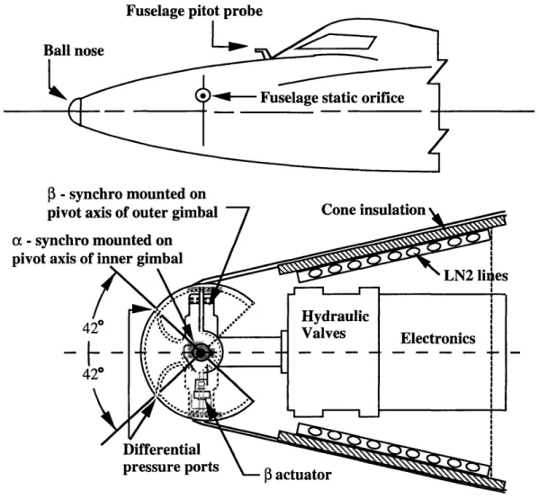
4-1 Schematic Drawing of the X-15 Ball Nose Sensor ... 46
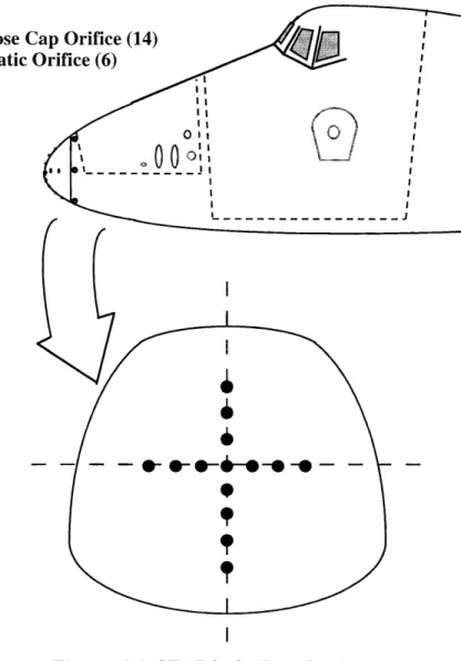
4-2 SEADS Orifice Configuration ... ... 47
4-3 Normal Acceleration vs Angle of Attack and Mach numbers ... 50
4-4 Useful Sensor Range ... 54
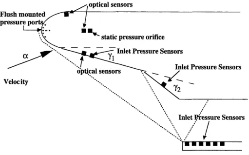
4-5 Air-Data Sensor Placement ... 55
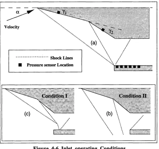
4-6 Inlet Operating Conditions ... 56
4-7 Inlet Analysis (1st Ramp Shock Angle vs a and M) ... 58
4-8 Inlet Analysis (2nd Ramp Shock Angle vs a and M) ... 58
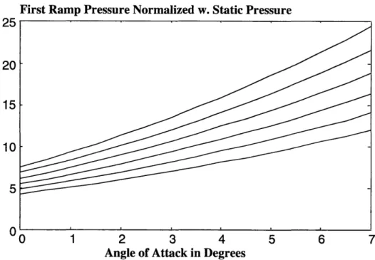
4-9 Inlet Analysis (1st Ramp Pressure vs a and M) ... 59
4-10 Inlet Analysis (2nd Ramp Pressure vs a and M) ... 59
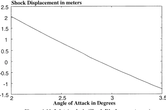
4-11 Inlet Analysis (Shock Displacement vs a ) ... 60
5-1 Decision Flow Charts for Vehicle Models... ... 64
5-2 Resulting Angle of Attack for Various Vertical Gusts... 65
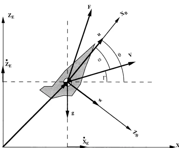
5-3 Definition of Coordinate System and Variables ... . 69
5-4 Block Diagram of AHSV Equations of Motion (M=3 to 6) ... 72
5-5 Plot of Drag Coefficient ... 74
5-6 Plot of Lift Coefficient ... 75
5-7 Plot of Moment Coefficient ... 75
5-8 Thrust coefficient -Axial Component ... ... 76
5-9 Thrust coefficient -Normal Component ... 76
5-10 Propulsion Moment Coefficient ... ... 77
5-11 Elevon Control Coefficient -X direction ... 77
5-12 Elevon Control Coefficient -Z direction ... 78
5-13 Elevon Control Moment Coefficient ... ... 78
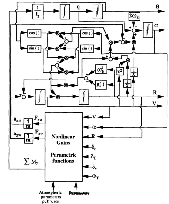
5-14 Block Diagram of AHSV Equations of Motion in LVLH frame (M > 6) ... 79
5-16 Plot of Coriolis Acceleration ... 81
5-17 M easurement Process ... 83
5-18 System Representation of GPS ... ... 85
5-19 System Representation of Gyro ... ... 86
5-20 System Representation of Accelerometer ... ... 87
5-21 System Representation of Pitot Probe ... ... 88
5-22 Detailed Block Diagram of Functional Relationship Between Surface Pressures to Air-Data States ... ... 89
5-23 Modified Newtonian Approximation of Round Nose ... 90
5-24 Plot of Rayleigh Pitot Formula (=-1.4)... ... 91
5-25 Pressure Port Model for SEADS Like System ... 92
5-26 Block Diagram of Rayleigh Scattering Sensor ... 93
5-27 Definition of Sensing Coordinate for Rayleigh Scattering Sensors ... 95
5-28 LIF Laser and Optical System Configuration ... 96
5-29 Definition of Sensing Coordinate for LIF Sensors ... 97
5-30 Information Route of Air-Data Sensor System ... 98
5-31 Zonal Assignment of Different Atmospheric Models ... 101
5-32 Temperature Distribution in the Standard Atmosphere ... 102
6-1 Block Diagram of Research Procedure ... 117
6-2 Estimator Design Procedure ... 118
6-3 Transient Response of Axial Velocity (Velocity Initial Condition Error of 10m/s) ... 123
6-4 Transient Response of Flight Path Angle (Velocity Initial Condition Error of 10m/s) ... 123
6-5 Transient Response of Pitch Rate (Velocity Initial Condition Error of 10m/s) ... 124
6-6 Transient Response of Pitch Angle (Velocity Initial Condition Error of 10m/s) ... 124
6-7 Transient Response of Axial Velocity (Flight Path Initial Condition Error of 0.5 deg.) ... 125
6-8 Transient Response of Flight Path Angle (Flight Path Initial Condition Error of 0.5 deg.) ... 125
6-9 Transient Response of Pitch Rate (Flight Path Initial Condition Error of 0.5 deg.) ... 126
6-10 Transient Response of Pitch Angle (Flight Path Initial Condition Error of 0.5 deg.) ... 126
6-11 Configuration of AHSV Flight Simulation (For Each Cell Block) ... 129
6-12 Simulation Procedure Block Diagram ... 130
6-14 Histogram of State Variables -Velocity & Angle of Attack (Mach 10)
(Gaussian Density Initial Conditions) ... 134
6-15 Histogram of State Variables -Pitch Rate & Pitch Angle (Mach 10) (Gaussian Density Initial Conditions) ... 135
6-16 Histogram of State Variables -Velocity & Angle of Attack (Mach 13) (Gaussian Density Initial Conditions) ... 136
6-17 Histogram of State Variables -Pitch Rate & Pitch Angle (Mach 13) (Gaussian Density Initial Conditions) ... 137
6-18 Histogram of State Variables -Velocity & Angle of Attack (Mach 15) (Gaussian Density Initial Conditions) ... 138
6-19 Histogram of State Variables -Pitch Rate & Pitch Angle (Mach 15) (Gaussian Density Initial Conditions) ... 139
6-20 Histogram of State Variables -Velocity and Angle of Attack (M= 10) (Uniform density Initial Conditions) ... 140
6-21 Histogram of Pressure Sensor Output ... 141
6-22 Histogram of Optical Sensor Output ... 142
6-23. Simulation Run Requirements ... 148
6-24 Velocity Perturbation Trajectory and Velocity Estimate ... 150
6-25 Angle of Attack Perturbation Trajectory and Angle of Attack Estimate ... 150
6-26 Pitch Rate Trajectory and Pitch Rate Estimate ... 151
6-27 Estimator Performance (Velocity Estimation Error) ... 151
6-28 Estimator Performance (Angle of Attack Estimation Error) ... 152
6-29 Estimator Performance (Pitch Rate Estimation Performance) ... 152
6-30 Histogram of Estimate Error. Velocity and Angle of Attack ... 153
6-31 Histogram of Estimation Error Pitch Rate ... 154
D-1 Block Diagram of AHSV Vehicle Dynamics ... 182
D-2 Controller Design for Vehicle Kinematics Stabilization ... 183
D-3 Controller Configuration When Inverse Map of G is Available ... 184
D-4 Inverse Map Obtained by Local Feedback ... 185
D-5 Slow Adaptation of Model Parameters Via Acceleration Measurements ... 186
D-6 Final Configuration of AHSV Controller ... 186
D-7 Force Control Block Diagram ... 187
D-8 Simplified Closed Loop of Control System ... 188
D-9 Closed Loop Block Diagram with Modeling Uncertainties ... 188
D-10 Block Diagram of Kinematic Controller C1 ... 192
List of Tables
4-1 Air-Data Requirements ... 51
5-1 Typical GPS Specification (civil code) ... ... 85
5-2 Typical High Performance Gyro Errors (1-sigma) ... 86
5-3 Example Precision of Accelerometer Errors ... 87
7-1 Sensor Precision Requirements for Case 1 ... 162
7-2 Sensor Precision Requirements for Case 2 ... 162
List of Symbols
And Acronyms
ADS Air-Data System
AHSV Air-Breathing Hypersonic Vehicle
Ae Elevon area
Ap Projected area
ag Slope of gradient layer ax Acceleration in x-direction ay Acceleration in y-direction az Acceleration in z-direction
a Angle of attack
Oad Design or desired angle of attack
b Vehicle wing span
3
Angle of side slipCARS Coherent Anti-stoke Raman Scattering CFD Computational Fluid Dynamics
CBE Coordinate transform matrix from earth to body coordinate CBW Coordinate transform matrix from wind to body coordinate CWE Coordinate transform matrix from earth to wind coordinate CD Aerodynamic drag coefficient
CDo Aerodynamic drag coefficient at zero angle of attack CL Aerodynamic lift coefficient
CLo Aerodynamic lift coefficient at zero angle of attack Cma Aerodynamic moment coefficient
Cmp Propulsion moment coefficient
CTn Thrust coefficient, normal to the velocity vector
Normalized Normalized Normalized Normalized Normalized Normalized Normalized Normalized Normalized
control force along the velocity axis due to the elevon control force normal to the velocity vector due to the elevon control torque in the pitch axis due to the elevon
control force along the velocity axis due to throttle variation control force along the normal axis due to throttle variation control torque along the pitch axis due to throttle variation control force along the velocity axis due to thrust vectoring control force along the normal axis due to thrust vectoring control torque along the pitch axis due to thrust vectoring Cx8, Cz, Cm8, CX&, CmG Cx8& Cza Cmay c DOF At
6e
8T
8v
EKF Fx Fy Fz f(.) GPS g, g(*) F Y HI-FADS HOT HTOL Hyflite He Hg Ho Hs h hk hpMean chord length for wing Degrees Of Freedom
Pulse duration Elevon control input Throttle control input Thrust vector control input Extended Kalman Filter Forces in x -Direction Forces in y -Direction Forces in z -Direction Function of *
Roll angle
Global Positioning System
Gravity constant, or gravity function (function of altitude) Flight path angle
Specific heat ratio
Subsonic High Angle-of-Attack Flush Air-Data Sensing System Higher Order Terms
Horizontal Take-Off and Landing Hypersonic Flight Test Experiment Free stream enthalpy
Gyro angular momentum Total enthalpy
Step function Altitude
Planck's constant Pressure altitude
hr Reference altitude for the environment model
lec Collection optic efficiency rid Detector quantum efficiency IMU Inertial Measurement Unit
I Vehicle moment of inertia matrix ( it's components Ixx, Ixy, etc.) Iga Moment of inertia -gimbal axis
I0 Source laser power Ir Rayleigh scattered power KBF Kalman-Bucy Filter KG Gravity coefficient
k Spring constant of the torsion bar
kd Viscous damping
LDV Laser Doppler Velocimetry LEO Low Earth Orbit
LHP Left Half Plane LTI Linear Time Invariant
LVLH Local-Vertical-Local-Horizon Ls Length of sample volume MIMO Multi-Input-Multi-Output
MIT Massachusetts Institute of Technology
M Mach number
Ma Flight Mach number
Md Design or desired flight Mach number Mx Moment on roll axis
My Moment on pitch axis
Mz Moment on yaw axis
M Free stream Mach number
m Vehicle total mass
mE Earth mass
NASA National Aeronautics and Space Administration NASP National Aero-Space Plane
Ni Number density of species i
np Number of pulses during the measurement interval v Radiation frequency
Vd Doppler shift frequency
Pi Pressure at ith pressure port
Pr Reference pressure for the environment model Pt Total pressure
P. Static pressure
p Roll rate
Q
Dynamic PressureQi Rayleigh cross-section of species i
q Pitch rate
0 Pitch angle
0g Gyro gimbal angle RHP Right Half Plane
R Distance from center of the Earth, altitude plus earth radius
Re Reynolds number
Rg Universal gas constant
Rp Ratio of static pressure over total pressure
r Yaw rate
Pe Engine inlet density
pr Reference density for the environment model
Poo Free stream air density
SEADS Shuttle Entry Air-Data System
SISO Single-Input-Single-Output SSTO Single Stage To Orbit
S Reference area, typically wing surface area
T Temperature
Te Engine inlet temperature
Tr Reference temperature for the environment model Tt Total temperature
T. Free stream air temperature
t Time
u X-direction velocity of vehicle c.g. Va Relative air velocity
Ve Engine inlet velocity
Vs Speed of sound
v Y-direction velocity of vehicle c.g. Wx Wind velocity in x-direction
Wy Wind velocity in y-direction Wz Wind velocity in z-direction
w Z-direction velocity of vehicle c.g.
Qc Solid angle of collection optics
WE Earth rotation rate
0)i Gyro rate input
Chapter 1
Introduction
1.1 Motivation
1.1.1 Historical Context
Until the fall of the Berlin wall, the main driving force behind the aerospace technology was the arms race of cold war. In the current era, characterized by the end of cold war and the beginning of an international economic race, aero-space programs can not follow the military oriented path of the past but rather should be stimulated by socioeconomic criteria. Technology developments in aero-space programs must emphasize international competitiveness in primary industries while also stimulating development of other engineering fields.
In recent years, enthusiasm for hypersonic flight research has been renewed by the promise of a fully reusable, horizontal take-off, single stage to orbit flight vehicle with air-breathing engines. The current state-of-the-art launch vehicles such as the Space Shuttle and expendable rockets have demonstrated their capabilities in the past; however, the existing vehicles are far short of an ideal launch system. Existing launch vehicles suffer from shortcomings in efficiency, reliability, and complexity. Projected
air-breathing hypersonic vehicles (AHSVs), such as was envisioned with the X-30 or National Aero-Space Plane (NASP) program, would potentially be very efficient [Peg 1].
A unique feature of this class of vehicles is the usage of air-breathing engines as the main propulsion system during most of the ascent trajectory. Since typical launch vehicles may allocate up to 90% of the vehicle weight to fuel and oxidizer, using atmospheric oxygen significantly reduces vehicle weight when compared to the rocket propulsion system with similar payload capability. For example, about 1/3 of the Space Shuttle mass, excluding the solid rocket boosters, are liquid oxygen [Lewl]. In the extreme case, liquid oxygen contained within the first three stages of the Apollo Saturn V launch vehicle contributed about 72% of its total weight [Lewl]. Full reusability and single-stage-to-orbit (SSTO) capability provides simplicity in operation and potentially cost effectiveness. Horizontal-take-off capability will eliminate complicated and costly launch facilities.
The inherent advantages of AHSVs make them quite attractive. The projected increase in demand for future spacecraft launches will justify the development of the AHSV technology; consequently, the AHSV concept qualifies as a future aero-space program justification criterion. Moreover, the derived new technology will be multi-faceted, since every aspect of building this class of vehicle would require innovation. High temperature materials, propulsion, system integration, control, sensors and estimation techniques are a few areas which can gain in their respective state-of-the-art by pursuing this program. Lessons learned from this vehicle development will greatly influence many industries.
1.1.2 AHSV Mission Requirements and Challenges
The anticipated result of the NASP research vehicle development program would have been an AHSV that would deliver a significant amount of payload to low earth orbit (LEO) via use of air-breathing engines [Pegl]. A future vehicle in the NASP class is expected to take off horizontally on conventional runway without complex launch facilities. The vehicle will have a single stage configuration that eliminates stage separation issues and insures full reusability. With a single stage configuration, the vehicle will cruise through the atmosphere following a narrow air-breathing corridor. The employed air-breathing engines will operate in both ramjet and Scramjet modes.
Hydrogen fuel will be burned with atmospheric oxygen ingested into the propulsion system. The total expected hypersonic flight time would be about 2000 seconds, longer than any existing launch systems [Hatl]. Once the vehicle gains speed to near orbital velocity, it will be inserted into low earth orbit with the assist of small rockets. Reentry will be performed using high drag maneuver similar to the Space Shuttle Orbiter following a trajectory much higher than the air-breathing ascent corridor at hypersonic speeds.
Operational requirements of an air-breathing hypersonic vehicle differ in many ways from conventional spacecraft and aircraft, mainly due to its unique propulsion system. Design of an air-breathing hypersonic vehicle will be dominated by considerations regarding air-breathing engine performance and stability, because the engine performance and stability will dictate the mission success. With likely slender lifting-body configurations, AHSVs will have propulsion, aerodynamics, and flight dynamics that are highly integrated and interactive [Sch2, Sch3, Pegl]. The vehicle lower surface would act as inlet and nozzle while providing lift. The flight control, guidance, engine control and vehicle cooling are heavily coupled to the propulsion system design; consequently, the major tasks of these subsystems would be to contribute to the proper combustion conditions. Propulsion, aerodynamics, and thermal constraints will be the main emphasis in the vehicle configuration design procedure. Moreover, the air-breathing engines of hypersonic vehicles will introduce restrictions on the flight trajectory envelope, vehicular motion and atmospheric conditions [Kan2].
Developing an efficient air-breathing propulsion system which can operate over a wide range of flight Mach numbers is a difficult task. Even though development of ramjet technology started as early as the 1950's, ramjet technology can only be used below about Mach 7 [Nasl]. The major difficulties in implementing conventional (subsonic combustion) ramjet technology are in the thermal limitations in combustor materials, inlet normal shock stability, combustor flame stability and the inherent problem of poor efficiency at low supersonic speeds and at Mach numbers greater than 7 [Petl]. The worst propulsion failure is called engine unstart that can occur if the normal shock position can not be properly controlled inside the compression inlet [Lehl, Sha2].
The technology of supersonic combustion ramjets which are called Scramjets promises good efficiency at higher Mach numbers [Kopl]. However, Scramjet technology is not yet mature enough to be implemented in an operational design. Many
problems associated with Scramjet technology are due to a still deficient understanding of supersonic combustion. Supersonic combustion chemical kinetics must be well modeled and managed to obtain stable and efficient combustion. Just injecting hydrogen fuel and promoting combustion in supersonic flow presents a substantial challenge [Kop1, Wall]. Inlet and nozzle design and the associated Aero-thermodynamics also must be fully understood and accommodated. Because of the high dynamic pressure, high Mach number flight conditions expected during Scramjet operation, materials capable of withstanding high thermal stresses are needed (greater than 3000F) [Kan2].
Both a theoretical understanding and experimental investigations of the aerodynamics and Aero-thermodynamics associated with hypersonic flight are needed. An understanding of the aerodynamic phenomena is required to determine vehicle dynamic variables such as stability derivatives, lift and drag coefficients. The vehicle control effectiveness can also be determined by investigating these aerodynamic problems [Cha2]. The aero-thermodynamics must be studied to determine the cooling requirements of the propulsion system and vehicle structure. The vehicle will have a hot structure configuration with long heat soak duration; therefore, an active cooling strategy must be developed [Peg 1, Wall, Lew 1].
Similarly, AHSV structural designs are also a challenge. Slender and shell structure lifting-body AHSVs are difficult to design and analyze due to their extreme temperature variation and heat loads. Furthermore, high temperature materials are difficult to find and then manufacture into vehicle components [Wall], and their strength and stiffness are difficult to estimate at extreme temperature. Even when such vehicle can be manufactured, it will be difficult to estimate the amplitude and frequencies of the vehicle vibration and bending modes. The resulting structural design may cause interaction problems with the control systems, propulsion, sensors and estimators.
Overall AHSV design is a difficult task since the interactions between subsystems are severe when compared to the conventional vehicles. Thus an AHSV must be designed as an integrated system instead of separate subsystems. For example, the flight controller can not be designed with conventional methodology based on just vehicle geometric and mass properties with experimentally derived stability derivatives. Given that the vehicle motion is heavily coupled to the air-breathing engines, and the engine control capability can be limited by actuator placement, complexity, bandwidth, and weight, the flight controller may be required to supplement the engine controller by
flying within specified attitude and maneuver ranges as a function of Mach number [Kan2]. Similarly the structural dynamics will be strongly interactive with the flight controller and propulsion systems; therefore, structural dynamics should also be addressed in the flight controller design process [Schl]. Due to the wide operating envelope of AHSVs, the flight control system includes highly nonlinear, time varying, and often unstable plants [Cha2].
Often the problem of state measurement and the associated data processing system is ignored as a serious problem during early flight vehicle development; however, for the AHSV, it is a very important problem to consider from design conception [Kan2]. The measurement and data processing system is the nervous system of the vehicle where the information is sensed, processed, and exchanged between the important functional subsystems. As part of integrated vehicle design methodology, the design of the measurement and data processing system must also be treated in integrated form. The design of sensors that can operate in such an extreme temperature environment is difficult. The hypersonic flow effects prohibit any sensors that intrude into the flow [Neul]. Also, accuracy and bandwidth requirements on sensors are stringent [Kan2]. Even if sensors can be designed and properly placed on the vehicle, it will still be challenging to manage and process thousands of measurements [Neul]. Furthermore, some measurements must be processed in real time thereby introducing constraints on data processing time.
Development of AHSV sensing and estimation capability can be categorized into several major tasks. The first task involves the control of information traffic; that is to define the transaction rules for the sensed and processed information. In other words, the task defines what parameters are needed by each subsystem, defines what measurements are available, and defines how sensed or processed information should interface between each subsystem. Also the transfer rate should be determined. The second task is to analyze the measurement process. In addition, the sensor noise and disturbance noise of measurement processes must be characterized. A third task is to provide algorithms that supply information in a compact and efficient form and provide an estimate of important variables. In order to solve such an involved problem, it is necessary to understand the overall system functionality as well as applicable requirements.
The performance and stability of air-breathing engines are highly dependent on the air data parameters which are the quantified description of air flow around the
vehicle. In other words, the performance and stability of the air-breathing engines can be characterized only if the nominal and perturbations of the vehicle attitude in the wind frame are specified. Past investigations of the sensitivity of ramjet and Scramjet performance with respect to air data parameters indicated that the operation of the air-breathing engines outside the design envelope severely degrades the propulsion efficiency and could lead to combustion instability [Kan2,Hatl]. For example, if angle of attack is off one degree from the design value then about 5% of total fuel will be wasted[Hatl]. The past and current rocket based hypersonic flight vehicles, such as X-15 and Space Shuttle, do not require the measurement of air data for the propulsion performance and safety. However, for the air-breathing hypersonic vehicles, the measurement and control of the air data parameters will play as important a role in their operational success as inertial platforms have for rocket propelled vehicles.
Other important physical variables are the parameters associated with flight environment. Describing the atmosphere around the flight trajectory, they are difficult to measure and are poorly known a priori. The variables such as free stream temperature, pressure, density, and wind vector distributions are required to operate the engine and flight control. For example, free stream static pressure and total pressure measurements along with free stream density are needed to fully characterize the true operating conditions of the engines. These operating conditions and the flow angle parameters are needed to adjust the fuel injection and other engine control variables. Therefore, along with engine parameters and air-data states, free stream atmospheric variables must be measured and processed. The data processing of atmospheric variables will involve estimation based on a combination of sensor measurements and the a priori data base.
The propulsion related parameters must also be measured and processed. The engine parameters, such as inlet thermodynamic states, mass flow rate and fuel flow are required to properly control the engine through throttle setting as well as inlet and nozzle geometry. Since the vehicle attitude regulation is also used as a method of engine control, those variables are needed by the flight controller to assist proper combustion. The applicable sensors are difficult to find since the sensors have to operate in an extreme temperature environment.
The interactions among subsystems described above calls for a system integration approach to measurement system design. With a full understanding of each subsystem, the inertial, air-data, propulsion, and environment sensing problem should be laid out
altogether and solved in an integrated manner. To demonstrate appropriate information processing methodologies and to obtain particular solutions would be significant, and enabling contributions to the development of AHSVs.
1.2 Research Objectives
The global objective of this research is to formulate and to demonstrate an air-data estimation strategy for Air-breathing Hypersonic Vehicles (AHSVs). In particular, the estimation efforts are focused on improving the air-data estimate accuracy, since there are stringent observation requirements which can not be addressed directly with accurate sensor readings. Even when applying all previously available knowledge of AHSVs, alternative estimation methodologies are needed, must be explored, and then evaluated on a realistic AHSV hypersonic flight digital simulation. The specific thesis research objectives are:
* To define AHSV measurement requirements by analyzing each subsystem such as engine control, flight control, guidance, and the vehicle cooling. In addition, analyze how required information is to be used by each subsystem. The accuracy requirements should be updated from previous work.[Kan2]
* To formulate the air-data estimation problem based on the accuracy requirements and available sensor technologies.
* To select and design applicable estimation strategies. The data processing schemes emphasize estimation of air-data states, propulsion parameters, and environment parameters. On the basis of fundamental nonlinear filtering theory and numerical analysis of a particular AHSV configuration, a particular solution of the air-data estimator should be designed and analyzed.
* To verify the estimator performance by obtaining a demonstrated solution to the estimation problem and performing statistical analysis. A computer simulation that has implemented the estimator concept should verify its performance.
* To assess the air-data sensor precision requirements in the context of air-data estimation. Relate the sensor issues such as applicability of currently available air-data sensor technologies and sensor precision requirements based on a demonstrated estimator solution and estimation constraints.
1.3 Contributions
* The development of a systematic approach to air-data estimator design methodologies that is applicable to any class of generic Air-Breathing Hypersonic Vehicles(AHSVs). This covers AHSVs with dynamic models that have nonlinearities within the vehicle flight dynamics, propulsion system, and measurement processes (observation equations).
* The treatment of coupled estimator and flight control problem that arise from the AHSV characteristics. Nonlinearities within the AHSV dynamics and observations result in solutions to the air-data estimation problem being dependent on control history. A flight controller is designed in the process of obtaining a particular solution.
* The assessment of air-data sensor precision requirements based on a demonstrated solution to the air-data estimation problem as well as a new method which is derived from the Extended Kalman Filter formulation to form inequality constraints with the state estimation error covariance and sensor noise covariance.
* A demonstrated solution to the AHSV air-data estimation problem. This includes:
* Graphical solutions to the Fokker-Planck equation of the AHSV
dynamics. That is based on a set of flight simulation runs with a statistical analysis.
* The Extended Kalman Filter design and its performance estimate based up on a Monte-Carlo simulation.
* An estimate of the air-data sensor precision requirements derived by using an iteration algorithm containing the covariance inequality constraints.
1.4 Organization of Thesis
Chapter 2 describes the research approach of this thesis. First part describes a global view of the thesis problem. Problem of the AHSV air-data estimation and constraints of the air-data sensing issues are qualitatively discussed to motivate the unique characteristics that are associated with this problem. Interactions between the air-breathing engines with other flight subsystems (most importantly with the vehicle attitude) are emphasized as the main motivation for the development of an accurate estimation strategy. Second part of this chapter presents brief solution strategies for the AHSV air-data estimation problem. The research tasks are presented in a systematic order and provide a general overview of the AHSV air-data estimation methodology.
Chapter 3 presents some introductory materials on the AHSV missions and configurations. Typical flight envelop and trajectory of the AHSV are presented with explanation of the air-breathing engine constraints. The most likely configuration of the AHSV is synthesized and discussed. The final AHSV design, that is being used within this thesis work, is configured based on the Chamitoffs AHSV design tools [Cha2]. Also this chapter discusses the status of the AHSV research. The last part of this chapter discusses the interactions between the air-breathing propulsion and other sub-elements of AHSVs such as structure and flight dynamics. The impact of these unique AHSV characteristics on the air-data instrumentation is discussed.
Chapter 4 discusses the AHSV air-data instrumentation issues. This chapter begins with the historical overview of hypersonic instrumentation. The air-data sensors from previous research and operational vehicles such as the X-15 and the Space Shuttle are discussed along with some other previously proposed conceptual sensor designs. This historical review of the potential sensor technologies provides the foundation for the AHSV instrumentation. The second part of this chapter presents the projected accuracy requirements of the air-data states. The accuracy requirements are derived in two perspectives, constraints from the air-breathing propulsion and the vehicle acceleration limits. The accuracy requirements are gathered and concluded from various sources such as [Kan2, Honl, Hatl] and several Space Shuttle documents. Also, the sensor selection issues are discussed. On the basis of functional characteristics of each applicable sensor candidate, sensor selection criteria are formed with the considerations from operational regimes, accuracy, and operation environment. The last part of this chapter discusses the sensor placement issues. The sensor installation criteria are motivated by the functional
characteristics of each sensor technology, shock structure and thermo/aerodynamics of the vehicle forebody, and the thermal loads.
Chapter 5 derives the necessary models for the AHSV dynamics, sensors, and simple environment models in the context of the AHSV air-data estimation. Two different models are presented to cover different flight regimes. First model contains wind effects and this model can be used to describe the vehicle motion during ramjet assisted flight (Mach 3 to 6). This model is derived and specialized to longitudinal motion from the 6 degree of freedom derivation of [Fro 1]. Second model is based on the LVLH formulation of [Cha2] and the equations are manipulated to treat angle of attack as one of the state variables. The inertial and air-data sensors are modeled such that the models are readily implementable for the estimation. The sensor models are simplified from the references [Prul, Hil3, Mill,Mil2, Mil3]. A simple environment model is presented.
Chapter 6 is a large chapter that discusses the air-data estimation methodologies. This chapter begins with the theoretical background necessary to understand and to derive the properties of the AHSV air-data estimation algorithm. The fundamentals of the estimation theory are briefly stated and the Extended Kalman Filter is derived from the fundamental equations as a special case.
The second part presents the estimation problem formulation. The equations from the models of vehicle dynamics and sensors are specialized to form a set of equations that represent the air-data estimation problem. The next section explains the AHSV air-data estimation strategy. The estimator design procedure is discussed from the problem formulation to the final performance verification stage. Control system design process is presented. The control system design has been motivated by the estimator's dependence on control history. Therefore a functional control system is designed and the performances are shown.
The next section presents a method of visualizing propagation of the state conditional densities. In order to guess at an appropriate approximation of the state conditional densities, the state conditional densities are visualized by multiple simulations and statistical analysis. The histograms of the propagation and update processes are plotted and presented. The results concluded that the Extended Kalman Filter should be a good approximation for this problem.
The last section demonstrates the Extended Kalman Filter development. The EKF design procedure is explained. A Statistical analysis (Monte-Carlo Simulation) is implemented and the necessary considerations are explained. The results from the statistical analysis are presented. The Gaussian assumption on probability density function of the estimation error is substantiated by the statistical analysis.
Chapter 7 provides a method to estimate the sensor precision requirements bounded by the estimator performance specifications. This chapter begins with the motivation for this analysis. An inequality constraint is derived from the EKF formulation. Later in this chapter, the solution strategy is demonstrated for several operational points and different sensor combinations.
Chapter 8 summarizes the thesis and discusses the conclusions. Also some recommendations for future research efforts are included.
Chapter 2
Research Approach
2.1 Problem Definition
The objective of this research is to understand and to develop the AHSV instrumentation and air-data estimation system. In particular, the research efforts have been focused on to the design and analysis methodologies of the AHSV air-data estimator with large emphasis on the air-data estimate accuracy improvement. The most important air-data state variables are the variables that depict air-relative attitude of the vehicle such as angle of attack. Throughout this thesis, several smaller pieces of problem are defined such that these problem definitions, solution strategies, and example demonstrations combined to layout the back bone of the design and analysis methodologies for the AHSV air-data system.
The measurement and data processing system is the nervous system of the vehicle where the information is sensed, processed, and exchanged between the important functional subsystems such as propulsion, thermal management, guidance and flight control. The instrumentation and information processing problem is critical to efficient and stable operation of AHSVs. For example, the engine control requires information on inlet, combustor, and nozzle flow parameters as well as vehicle motion (direct interdependence between propulsion and vehicle motion, Chapter 3) in order to execute
the feedback control law. Since the vehicle flight dynamics are highly nonlinear, unstable, and time varying, active control of vehicle motion is inevitable for both flight control and propulsion. Therefore, an accurate estimate of important states and parameters is absolutely necessary.
The AHSV state information can be obtained either by direct measurements and/or by processed measurements that are derived by numerical techniques such as nonlinear state estimation. Similarly instrumentation and information processing systems are needed by flight control, guidance, the structure thermal management, and various hypersonic experiments. In particular, the information on air-data states and propulsion parameters are considered as the most critical variables for the estimation.
The interaction among functional subsystems of AHSVs complicates the estimation problem formulation. The variables for the vehicle flight dynamics have direct inter-dependence with the propulsion state variables. In order to achieve greater estimation accuracies, it is desirable to treat all air-data sensitive elements of the AHSV. As a result, the problem formulation requires augmentation of all the interacting elements of interdependent functional blocks. The required information can be acquired through various sensors located around the vehicle combined with a priori knowledge or data about the systems prior to flight. It is a challenging task to provide methods to distribute and integrate these numerous information sources so as to insure a proper and efficient operation of the vehicle propulsion systems.
A part of this thesis research effort involves understanding of how each functional subsystem behaves during the hypersonic flight. For each subsystem, it is necessary to define what are the important states and how they affect the overall flight performance and stability. If these states require monitoring or control, then the accuracy and bandwidth requirements on these states must be defined. Also, design of sensors that can operate in the applicable extreme temperature environment is difficult. Therefore another part of this research involves selection of applicable sensors, and sensor placement. The measurement requirements and sensor issues lay out a foundation for the AHSV air-data estimation problem.
Once the air-data estimation problem is defined, another challenge is to find an appropriate estimation strategy. The problem is to determine what type of signal processing and/or estimation strategy would be most applicable for that particular
assignment. Because the AHSV problems contain nonlinear elements, the selection of an appropriate estimation algorithm is not trivial. Since a model based estimation strategy is considered to be the most appropriate strategy, the required models should be formed. The modeling problem is also a challenging problem since all the elements of hypersonic flight and air-breathing propulsion should be addressed without complicating the representing models. The measurement processes (including sensors) are needed to be modeled. After an estimation strategy is established, next issue is to develop algorithms which provide a compact and efficient source of processed information derived from measured data set. The algorithms and the selected set of sensors must provide estimates of important variables within the required accuracy and bandwidth.
Once the air-data estimator is developed, some measure of its expected performance is needed. Since the problem involves stochastic response of the nonlinear dynamics, a statistical analysis is needed for the system performance verification. The algorithm implementation issues and the system practicality should be addressed. Due to the unique nature and complexity of the AHSV information processing system, demonstration of the information processing methodology and obtaining particular solutions would be a significant contribution to the development of AHSV technology.
The last problem of this thesis is the assessment of the air-data sensor precision requirements. For this given air-data estimation problem, the problem of finding an upper bound of the sensor performance requirements can be defined This problem would be a significant interest to the hypersonic air-data sensor designers. The AHSV air-data sensors are still under development. Most of the proposed sensor technologies are either laboratory techniques or conceptual stage. By obtaining a method to bound an upper bound of the sensor performance and providing a demonstrated solution, the results may
2.2
Solution Strategy
In an attempt to solve the problem defined in section 2.1, a solution strategy is laid out and will be discussed in this section. The solution strategy for the AHSV instrumentation and air-data estimation can be briefly summarized as follows. The first phase of this research is in understanding of the AHSV system. The instrumentation and information processing requirements of each functional block are defined. Once the requirements are defined, the engineering analysis that is based on physically available hardware provides the basis for the problem formulation in the context of the air-data estimation. The second phase involves the air-data estimation problem formulation and the system modeling. Once the important states and parameters are selected, models of the interacting functional elements are created. These models include sensors, vehicle dynamics, and the environment. The third phase involves formulation of estimation algorithms. On the basis of the problem formulation and the related system models, a simulation based analysis is performed to provide a clue to the estimator design solution. The last phase addresses the performance verification and the numerical implementation issues along with some recommendations for the sensor precision requirements.
Phase I: By investigating the detailed characteristics of AHSV subsystems such as vehicle configurations, guidance and control requirements, detailed propulsion characteristics, and flight dynamics, the measurement and information flow requirements are defined. There are several previous investigations on flight dynamics and control, trajectory optimization, and propulsion in both theoretical and experimental forms. On the basis of these studies as applied to the selected vehicle configurations, the AHSV measurement requirements are defined with emphasis on air-data states. A candidate set of inertial, air-data, and propulsion sensor technologies that can span the AHSV flight envelope is selected on the basis of functional requirements and first principles of sensor operation. These sensors may utilize mechanical, pressure, and advanced optical measurement techniques. With the list of applicable sensors, the AHSV operational requirements, and the information flow structure, the basis for the problem formulation is formed.
Phase II: The model based estimation approach is the most applicable for AHSV air-data state estimation. The AHSV flight dynamics contain full of air-data information. The force components are direct function of thermo/aerodynamic parameters, angle of attack and velocity. Therefore, the model of AHSV dynamics can
boost the information on the air-data states assuming that a sufficiently accurate model can be obtained. Once the model based estimation strategies are considered, the models for vehicle dynamics, propulsion, environment, and sensors are formulated. The vehicle and propulsion models are developed based on the NASA Langley [Shal] and Draper Lab data bases [Cha2]. The sensor model formulations are based on the first principles of operation and/or previous implementation results. Also the corresponding sensor noises and disturbances will be modeled and characterized. The review of existing data and conceptual preparation on wind information, and some of the propulsion coefficients lead to the necessary models.
The environment model, by definition the free stream parameters such as pressure, temperature, density, and wind velocity vector field, are incorporated within the vehicle flight dynamics. The propulsion and aero-thermodynamics describing the AHSV dynamics contain the parameters that are depend on the environment model parameters. Therefore, the models are needed to be updated by measurements and processed in order to implement the estimation strategy. This information should also be distributed for the engine and flight controller.
Once the measurement and data processing requirements are established, the estimation problem is formulated. A first task is to define the states to be estimated. With laid out models for sensors, sensor noises, vehicle dynamics, and environment, a model based estimator block diagram is constructed. Part of the problem is in dynamic state estimation form, while other parts are in the form of static filtering. Due to the vehicle dynamics and sensor characteristics the problem involves treating nonlinear, time varying, unstable, and nonlinear observation processes.
Phase III: In order to solve the estimation problem defined in phase II, nonlinear filtering theory is reviewed and applicable filtering strategies are composed. In order to acquire an approximate solution for the AHSV air-data estimator, it is desirable to know the characteristics of the state conditional densities. A visualization tool based on a statistical analysis is recommended. Initially the Extended Kalman filter (EKF) is considered since it is the easiest to implement. However, the implementation of EKF requires certain assumptions on its state conditional densities and the AHSV air-data estimation problem should be analyzed to verify its applicability. The visualization tool would provide some evidences for the applicability of EKF. If EKF fails as the solution
to the estimation problem, the estimator design can be approached in more fundamental methods.
The problem posed by the AHSV air-data estimation requires a control system design. When looking into the evolution of the state conditional densities for the AHSV air-data estimation problem, the governing equation depends on specific control history, measurement, initial conditions, and operation boundary conditions. Consequently, the solutions will depend on a specific controller design.
Throughout the estimator design phase, a statistical analysis tool such as the Monte-Carlo simulation may be used to characterize the problem. Because of the fact that the estimation problem is a nonlinear problem, an achieved solution will depend on a specific design and operating condition. The obtained results will be used to reassess the air-data sensor precision requirements.
Phase IV: Once a reasonable estimation strategy is selected and an
appropriate estimator is designed, full scale simulation is needed to be performed with both the plant, which consists of high fidelity models of vehicle dynamics, sensors, and disturbances, and the estimator, which is designed based on simpler models with uncertainties in model coefficients. Through Monte-Carlo analysis, the performance of the designed estimator can be estimated. Engineering analysis is then used to address issues regarding numerical implementation, and estimator characteristics.
With the estimation results, the issue of air-data sensor precision requirements can be addressed. Also, if possible, an upper bound of the sensor precision requirements should be derived. With these results, some recommendations for the sensor accuracy requirements can be made.
Chapter 3
AHSV System Overview
3.1 Air-Breathing Hypersonic Flight
3.1.1 Air-Breathing Corridor and Flight Trajectory
The air-breathing ascent trajectory is determined by air-breathing combustion requirements and thermal load considerations in addition to guidance requirements. For a given speed, air-breathing engines require bounded ranges of atmospheric pressure, density and temperature for proper combustion, thus the requirements set a particular Mach number - altitude envelope called the air-breathing corridor. More detailed trajectory optimization results based on these requirements can be found in [Hat2]. The trajectory restrictions, along with maneuver restrictions and bounds of allowable environmental conditions, set part of the requirements for sensor selection and operation. Thus these bounds or results can be used to obtain the particular operating conditions for AHSVs. Therefore, the results will be applied as nominal conditions throughout the thesis analysis. Since more detailed work can be found in [Hat3, Kan2, Lewl], the requirements are briefly stated, then more importantly, the resulting operating conditions will be used to provide nominal conditions for the models within the estimators during numerical simulations.
300-S h u t t le Entry S200-S100 Air-Breathing Corridor .. 5 10 15 20 25 Mach Number
Figure 3-1 NASP Trajectory Corridor
The combustion requirements can be briefly summarized as follows. The combustor inlet temperature must be low enough to permit addition of heat to the flow with an increase in enthalpy. At sufficiently high temperature, added fuel will dissociate, and the dissociation will absorb energy and result in a net loss of heat from the flow. On the other hand, the combustor inlet temperature must be high enough to create spontaneous combustion [Lewl]. Combustor inlet pressure must be as high as the structure can withstand to maximize combustion efficiency; however, if inlet temperature is low, then the inlet pressure must be kept below the cutoff pressure where secondary reactions start [Lewl]. Therefore, inlet pressure and temperature should be controlled within a narrow range. Detailed numerical data on combustion requirements can be found in [Lewl, Cha2, Kan2]. Typical dynamic pressure bounds of 500 to 2000psf are expected during most of the hypersonic flight phase and up to a 3000'F peak temperature is expected on the vehicle structure. The constraints defined by combustion and structural loads will dictate a flight envelope similar to the air-breathing corridor shown
in Figure 3-1. Most of the hypersonic flight will occur within the 100k to 200k ft altitude range. Total air-breathing flight time will be about 2000 seconds [Hatl].
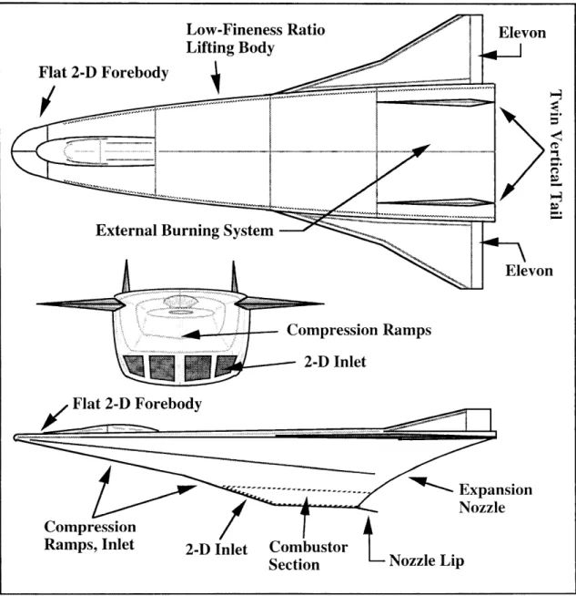
Figure 3-2 AHSV Configurations
3.1.2 AHSV Configuration
The proposed AHSV will have low fineness ratio lifting body configuration as shown in Figure 3-2 [Wall, Schl]. A total vehicle length and weight of 150 ft and
250,000 LB are expected [Schl]. The vehicle will have flat 2-D forebody which acts as a Ramps 2-D Inlet Flat 2-D Forebody "J -- ...--- ". ' " E xp an sion
SExpansionzzle
CompressionRamps, Inlet 2-D Inlet Combustor
L Nozzle Lip Section