HAL Id: in2p3-00020054
http://hal.in2p3.fr/in2p3-00020054
Submitted on 15 Jul 2003HAL is a multi-disciplinary open access archive for the deposit and dissemination of sci-entific research documents, whether they are pub-lished or not. The documents may come from teaching and research institutions in France or abroad, or from public or private research centers.
L’archive ouverte pluridisciplinaire HAL, est destinée au dépôt et à la diffusion de documents scientifiques de niveau recherche, publiés ou non, émanant des établissements d’enseignement et de recherche français ou étrangers, des laboratoires publics ou privés.
Technical report on operating accelerators 2001-2002
E. Petit, A. Savalle, B. Jacquot, F. Chautard, P. Dolegieviez, P. Robillard, M.
Ozille, M.H. Moscatello, F. Loyer, A. Peghaire
To cite this version:
E. Petit, A. Savalle, B. Jacquot, F. Chautard, P. Dolegieviez, et al.. Technical report on operating accelerators 2001-2002. [Research Report] GANIL. 2003. �in2p3-00020054�
GANIL R 03 02
Grand Accélérateur National d’Ions Lourds
Laboratoire commun CEA/DSM-CNRS/IN2P3
TECHNICAL REPORT
ON OPERATING ACCELERATORS
2001 – 2002
GRAND ACCELERATEUR NATIONAL D’IONS LOURDS – LABORATOIRE COMMUN CEA / DSM – CNRS / IN2P3 BP 55027 – 14076 CAEN Cedex 5 – TEL. 02.31.45.46.47 – FAX 02.31.45.46.65 – www.ganil.fr
Fig.1
CONTENTS
1. ACCELERATOR OPERATION:
1.1 Accelerator operation in 2001 and 2002
1.2 Evolution of operation since 1996
2. MACHINE STUDIES:
2.1 Machine studies in 2001 and 2002
2.2 Beam optic studies and Accelerator operation
2.3 Beam studies inside CIME – Beam tests inside CIME
3. TECHNICAL DEVELOPMENTS:
3.1 A cryogenic target for secondary ion beams
3.2 Efficiency and production yield measurements of
radioactive O,N and F for the SPIRAL facility
3.3 Metallic ion beam developments
4. THI :
4.1 OPTHI project
4.2 THI 6KW project
5. NEW EXPERIMENTAL FACILITIES
5.1 IRRSUD
5.2 LIRAT project
Appendix #1 :
- Experiments conducted in Nuclear Physics in 2001 and 2002
- Experiments conducted in Non Nuclear Physics in 2001 and
2002
- Available ions at GANIL
- Accelerated beams with their characteristics
- SPIRAL beams : radioactive ion beam intensities
Appendix #2 :
- List of publications
Front page :
Fig1: Hydrogen target solid growth
FOREWORD
This issue of the Technical Report about the Accelerators describes the operation
for physics experiments and beam tests, various technical improvements and projects for
the years 2001-2002 during which the most eventful result was the start of the SPIRAL
facility operation.
As usual the first chapter reports on the standard operation of GANIL with stable
as well as radioactive beams, an analysis of the beam time distribution and statistics. Of
course the most prominent event has of course been radioactive beams delivered for
nuclear physics experiments. Then a status and an analysis of operation since 1996, with
the evidencing of the increase of beam availability for physics experiments and the decrease
of tuning time, are conveyed in this first chapter.
Beam tests were very numerous during these two years. In 2001, beam tests time
were dedicated essentially to THI (beam instrumentation, understanding of THI beam
power limitation to 3 kW) and to SPIRAL beam tests with radioactive beams. In 2002, less
beam tests were planned during operation, nevertheless many tests with SPIRAL stable
beam took place in parallel with operation for physics experiments. This is the content of
the second chapter.
Technical studies, essentially concerning ion sources developments on stable and
radioactive beams, are described in chapter 3.
During these two years THI project ( chapter 4) carried on in the form of two
projects called OPTHI and THI6K. OPTHI project allowed the routine operation of THI
beams needed for the production of radioactive beams with SISSI and SPIRAL facilities,
and also enabled the extension of THI beams for experimental areas. THI6K project,
whose objective was to accelerate a 6 kW beam, proved the existence of longitudinal charge
space effects in SSC2 limiting accelerated beam power. The decrease of the number of
beam turns inside SSC2, in increasing the voltage of RF cavities, enabled the extraction of
a 5 kW beam of
36Ar.
The last chapter deals with a facility, called IRRSUD, which uses the low energy
beams coming from the injectors. This new facility has been commissioned with beam and
used for the first physics experiments in 2002. A status progress of the LIRAT project,
which is a new very low energy radioactive beams line using beams produced with the
SPIRAL Target and Source device and which will offer new possibilities for physics, can
also be found in this last chapter.
Eric PETIT
Head of the Accelerator Division
PREFACE
Ce numéro du rapport technique des accélérateurs décrit le fonctionnement pour la
physique, les études machine, les améliorations techniques et les projets pour la période
2001-2002 qui a été marquée par le démarrage de SPIRAL en faisceaux radioactifs.
Le premier chapitre décrit comme il est de tradition le fonctionnement des
accélérateurs avec des faisceaux d’ions stables mais également radioactifs, l’analyse de la
distribution du temps de fonctionnement et les statistiques. Le fait le plus important a bien
évidemment été la fourniture de faisceaux radioactifs pour la physique nucléaire. Puis dans
ce premier chapitre, un bilan et une analyse sont faits du fonctionnement des accélérateurs
depuis 1996, avec la mise en évidence de l’augmentation du nombre d’heures faisceau
fournies à la physique et la diminution des temps de réglage.
Les études machine ont occupé une place importante durant ces deux années. En
2001, le temps d’étude machine a essentiellement été consacré à THI ( instrumentation de
faisceau, compréhension de la limitation de la puissance faisceau à 3KW à l’éjection de
CSS2) et aux tests de SPIRAL en faisceau radioactif. En 2002, moins de temps d’études
machine a été programmé sur le temps de fonctionnement des accélérateurs, cependant en
parallèle de la fourniture de faisceau à la physique de nombreuses études machine ont été
dédiées à l’accélérateur SPIRAL notamment en faisceau stable. C’est l’objet du second
chapitre.
Au chapitre 3 sont évoquées les études techniques qui ont essentiellement
concerné les développements sur les sources d’ions aussi bien en faisceaux stables ( ions
métalliques) qu’en faisceaux radioactifs (études sur SIRA).
Le projet THI (chapitre 4) s’est poursuivi durant ces deux années sous la forme de
deux projets appelés OPTHI et THI6K. OPTHI a permis la mise en exploitation courante
de faisceaux THI nécessaires pour la productions de faisceaux radioactifs avec SPIRAL et
SISSI, et a aussi permis l’extension de THI vers les aires expérimentales. THI6K, dont
l’objectif était de parvenir à accélérer un faisceau de 6KW, a démontré l’existence de l’effet
de charge d’espace longitudinal dans CSS2 limitant la puissance faisceau accéléré. La
diminution du nombre de tours faisceau, en augmentant les tensions des cavités HF de
CSS2, a permis d’extraire un faisceau d’
36Ar de 5.2 KW.
Le dernier chapitre décrit la fin de construction de la ligne basse énergie IRRSUD
qui a été testée avec faisceau puis utilisée pour de premières expérience de physique durant
l’année 2002. Ce dernier chapitre est également l’occasion de faire le point sur
l’implantation au GANIL d’une nouvelle ligne d’ions radioactifs très basse énergie,
appelée LIRAT, utilisant directement les faisceaux issus de l’ensemble Cible/Source de
SPIRAL et offrant ainsi de nouvelles possibilités pour la physique.
Eric PETIT
1
ACCELERATOR
OPERATION
1.1 ACCELERATOR OPERATION
in 2001 and 2002
A. Savalle
1 Highlights
2001
Two major failures occurred during the first two weeks, implying several days of intervention. The first one was related to the vacuum system of the rebuncher R1, while the second one was concerning the cooling system of SSC1 cyclotron.
After this period, the failure rate was normal and the experiments were carried out with no major difficulties.
During the second period, a high intensity 48Ca (I>2.6 µΑe corresponding to 400 W) was accelerated for three weeks. Despite the high intensity, the stability and the mean consumption were excellent. In July, the first tests of the beam line L4 (which is used to transfer the beam towards the SPIRAL target-source) were made.
The administrative authorization needed was finally obtain in August. The two first SPIRAL beams were delivered to the experimental areas, in September and November : 18Ne at 7 MeV.A and 8He2+ at 15.5 MeV.A. To product this 8He beam, the first THI beam (1 kW 13C6+) was directed towards the SPIRAL target.
The THI project was pursued, and the difficulties related to high intensity beam dynamics overcome. Consequently, for the first time, a 5.2 kW beam ( 36Ar18+) could be accelerated.
2002
The accelerator operation started on March 11th, without any special difficulty.
Several SPIRAL beams ( 8He, 6He, 76Kr, 74Kr ) have been accelerated at several energies. The list is given bellow.
The primary beam intensity is, for the while, limited to 1.4 kW, for thermal reasons. In fact, in march , 2 target-Ion-Source-systems (TISS) broke, in presence of a beam power inferior to 1.3 kW. This failure was interpreted as a vacuum failure, due to thermal constraints on an alumina piece. After some mechanical modifications, a beam power of 1.4 kW was reached without difficulty. To enable the use of higher power beams (as 3 kW 13C6+), the target itself is to be modified.
A major failure occurred in October : a water leak inside the RF cavity of SSC2. The intervention lasted for three weeks. During this period, the beam was delivered to SME and to IRRSUD, for technical tests.
2. Accelerated beams
2001
ion
36Ar
36S
20Ne
124Xe
136Xe
129Xe
129Xe
12C
208Pb
1st periodEnergy
(MeV.A
)
95
77.5 95
45 45 27 35 95 29
ion
40Ar
16O
36S
48Ca
20Ne
18O
2nd periodEnergy
(MeV.A
)
5 13.7 50
60
95 63
ion
13C
18O
20Ne
58Ni
36S
3rd periodEnergy
(MeV.A
)
60
63 95
75 77.5
ion
13C
36Ar
86Kr
4th periodEnergy
(MeV.A
)
75
95 58
THI Beams
Ion Energy
(MeV/u) Use Beam
Power
(kW)
PPS
36
S
16+77.5 SISSI
(x2)
1
2.3 10
12 20Ne
10+95 Machine
study
3
10 10
12 48Ca
19+60 SISSI
0.6
1.3 10
12 58Ni
26+75 SISSI
0.8
1.2 10
12 13C
6+75 SPIRAL
1.4 (3 output
SSC2)
9 10
12 36Ar
18+95 Machine
study
5.2 (3 in
operation)
9.4 10
12 86Kr
33+58 LISE
2000
0.66
0.8 10
12SPIRAL BEAMS
Ion Energy
(MeV/u)
PPS
18Ne 7 1.
10
6 8He 15.5
1.3
10
42002
Ion Energy
(MEV.A)
Accelerator THI
36
Ar
4.9 SSC1
36Ar
95 SSC2
48Ca
60 SSC2
0.55 kW
13C
75 SSC2
1.3 kW
208Pb
5 SSC1
78Kr
68.5 SSC2
0.65 kW
58Ni
4.3 SSC1
13C
75 SSC2
1.4 kW
208Pb
29 SSC2
13C
75 SSC2
1.4 kW
76Ge
59 SSC2
129Xe
7 SSC1
36Ar
95 SSC2
13C
75 SSC2
1.4 kW
18O
55 SSC2
64Ni
55 SSC2
64Ni
4.4 SSC1
SPIRAL BEAMS
Ion
Energy
(MeV.A)
Intensity (pps)
8He
1+3.5, 3.4, 3.9
(5 to 8) x 10
+48
He
2+13
15.7
2.5 x 10
+41.8 x 10
+4 6He
1+3.25
1.7 x 10
+7 6He
1+5
3.2 x 10
+7 76Kr
4.4
1 x 10
+676
Kr
2.6
6 x 10
+574
Kr
2.6
1 x 10
+43 OPERATING STATISTICS :
2001
The time available for users decreased, due to waiting for the administrative authorisation for SPIRAL, the SPIRAL beam tests, and an important part of beam time dedicated to the THI machine studies.
Scheduled beam time distribution from 5 March to 16 December 2001 Hours %
Preparation of beams 726 13.1
Nuclear Physics (HE) 3064 55.4
Non Nuclear Physics (HE) 286 5.2
Physics Tests 301 5.4
Machine beam tests 440 8.0
Waiting for Spiral authorisation 102 1.8
Spiral beam tests 276 5.0
Technical Interventions 224 4.0
Not defined 115 2.1
total 5534 100.0
Operation from 5 march to 16 december 2001
waiting for users 3.7%
waiting for SPIRAL authorisation
2.2%
technical interventions 3.9%
machine beam tests 11.9% failures 11.4% Tuning 12.9% Nuclear Physics 47.8%
Non Nuclear Physics 3.7%
physics tests 2.5%
2002
The availability for users increased, due to an important decrease of the time allocated to machine beam tests.
Indeed, the main part of the accelerator development was dedicated to SPIRAL. These machine studies may generally be carried out using a CIME stable beam, while a SSC1 or SSC2 beam is available for physics.
Scheduled beam time distribution from 11th march to 20th December 2002 Hours %
Security (UGS) tests 104 1.8
Preparation of beams 848 14.8
Nuclear Physics (HE) 3216 55.9 Non Nuclear Physics (HE) 450 7.8
Physics Tests 277 4.8
Machine beam tests 206 3.6
Not defined 648 11.3
total 5749 100.0
Operation from 11 march to 20 december 2002
Beam available = 67.2%
SME-IRRSUD 4.1% waiting for users
3.7% Physics tests
5.4% Non nuclear Physics
7.2%
Nuclear Physics 46.8%
machine beam tests 2.7% technical Interventions 3.1% failures 10.9% tuning 12.4% Strike 2.3% Security tests 1.5%
4 Failures Statistics
The distribution of the failures is the following :
2001 Hours % Power supplies 40.5 6.7 Electronics 8.25 1.3 Control-command 66.5 11.0 Logic controllers 12.75 2.1 R.F. 261.75 43.3 ECR Sources 62 10.25 SISSI 4 0.7 Cooling circuit 22.25 3.7 vacuum 52.25 8.6 Spr UGSR UGSA 25.25 4.2 Beam stops 9.5 1.6 Electricity 2.75 0.45 Other 37 6.1 total 604.75 100
Two important failures, related to R.F. equipment, occurred in march 2001.
The first one was related to the vacuum system of the rebuncher R1, while the second one was concerning the cooling system of the north cavity of SSC1 cyclotron.
2002 heures % Power supplies 78.75 13.78 Electronics 9 1.57 Control-command 3 0.52 Logic controllers 1.5 0.26 R.F. 92.75 16.23 Water leak RF SSC2 148 25.89 ECR Sources 3.25 0.57 Cooling circuit 15.25 2.67 vacuum 26.5 4.63
Security (UGSR, UGS2) 46.25 8.09
Beam stops 8.5 1.49
Electricity 3.25 0.57
ECS source 70.75 12.37
Other 65 11.37
571.75 100
The cooling circuits of the RF cavity are the main cause of failure.
In addition to the water leak inside the RF cavity of SSC2, one has been encountered again on the north cavity of SSC1, while another was discovered on the dee of C02 injector. That dee has been totally rebuilt during winter 2003.
An important failure occurred, and is still present, concerning the main coil of CIME cyclotron (internal short-circuit). The characteristics of the main coil are changed, but not the working diagram of CIME.
1.2 EVOLUTION OF OPERATION SINCE 1996
A. Savalle
1 Beam availability and availability for physics
The availability for users was below 2500 hours in 1997-98, related to the construction of SPIRAL. Since then, the number of operation weeks has regularly increased (up to 35.5 weeks en 2002). Furthermore, the percentage of beam availability for users increased in 2002. Thus, the beam was used by physics during more than 3500 hours.
1500 2000 2500 3000 3500 96 97 98 99 2000 2001 2002
beam used by physics (hours)
The beam availability includes, not only the availability for physics, but also the accelerator development. For example, the availability for physics is the lowest in 2001, due to the first SPIRAL tests and to major THI developments. However, the beam availability is higher in 2001 than in 1999, when several THI machine studies were cancelled.
Similarly, although the beam availability is not exceptional, the physics part is the highest in 2002. Indeed, the major part of the accelerator development has been made with a CIME stable beam.
Beam Availibility 45,00 50,00 55,00 60,00 65,00 70,00 75,00 96 97 98 99 2000 2001 2002 years %
beam used by physics
beam available (physics+machine studies+waiting)
beam used (physics+machine studies) machine studies 0.00 2.00 4.00 6.00 8.00 10.00 12.00 14.00 96 97 98 99 2000 2001 20/12/02 %
2 Evolution of tuning time
The tuning time is (in percentage) decreasing for several years.
First of all, note that this percentage is related to ratio (number of accelerated beams / number of operation weeks). In 1998, 28 beams were accelerated during 26 operation weeks. In 2001 and 2002, 25 beams have been accelerated during 35 weeks. This was obtained by grouping the experiments using the same beam together.
Nevertheless, an evolution can be seen from 1996 to 2002 (same number of accelerated beams). It can be explained by two ways :
- as far as SSC1 or SSC2 are concerned, the methods of tuning have been improved - The CIME beams are planned so that the main part of the tuning is realized with a stable
beam, while a SSC1 or SSC2 beam is delivered to physics. Similarly, the CIME stable beam may be used during the tuning of SSC1 and SSC2.
0 5 10 15 20 25 96 97 98 99 2000 2001 2002 years
nb of accelerated beams/(10 weeks) tuning (%)
3 Evolution of failure rate
The failure rate has slightly increased for several years. A part of this evolution may be related to the number of equipments (SPIRAL). However, the several water leaks which occurred these last years are related to the age of the GANIL accelerator.
0.0 0 2.0 0 4.0 0 6.0 0 8.0 0 1 0.0 0 1 2.0 0 9 6 9 7 98 99 2000 2 00 1 2 00 2 y ea rs % failu re s
2
MACHINE
STUDIES
2.1 MACHINE STUDIES in 2001 and 2002
A. Savalle
2001
12 % of operation time were devoted to machine studies, including the first SPIRAL tests with radioactive beam. The different subjects were :
• Beam instrumentation • Automatic beam tuning
• THI :
The existence of longitudinal space charge effects in SSC2 was demonstrated. These effects were limiting the beam power to 2.5- 3 kW. It was shown that it was necessary to decrease the number of turns in SSC2, thus to increase the RF voltage. This voltage was increased up to 220 kV, in December 2001, and a 5.2 kW beam power was produced (36Ar18+ beam).
o Study of the beam dynamics in C01 injector o Study of the effect of the transverse emittance
o
Development of digital feedbacks to stabilize the beam• SPIRAL :
o Study of the CIME (stable) beam characteristics in the “Z” spectrometer
o test of the beam line L4 : a 20Ne beam, at 95 MeV.A, then a 13C beam at 75 MeV.A, were directed to the Target-Ion-Source-System (TISS), through the beam line L4. The aim was to check the equipment, the transmission, the beam width on target.
o Test of SPIRAL TISS
o Test of the low-energy Identification station, and of the CIME instrumentation for radioactive beam
o Test of the tuning method for radioactive beams, by extrapolation of a stable beam of similar q/A.
2002
2.7 % (130 hours) of operation time were dedicated to machine studies : - Tests of THI security system.
- Beam instrumentation - Automatic beam tuning
- Study of the beam dynamics in C01 injector
- Irradiation of a copper target, to measure the activation
- Measurement of the production rates of several beams, with the SPIRAL low-energy Identification station
These 130 hours have needed an interruption of beam delivery to physics. In addition, 250 hours have been dedicated to machine studies using a CIME stable beam. The different subjects were :
- Study of the TISS extraction
The extraction optics depends on the extracted ions and on the intensity. Moreover, a misalignment defect is present (estimated to 1 cm at the output of the einzel lenses). The tuning of the injection beam line (from TISS to CIME) is complicated by these two phenomenon.
- Tuning methods from stable beam to exotic beam
Two methods may be applied : change of the magnetic field level or change of the RF frequency, according to the formula : B*R = γmv/q. Using anyone of these two methods, the difficulty is higher at high energy (harmonics 2 and 3) than at low energy (harmonics 4 and 5). It can be explained by two facts : the number of turns which is higher in harmonics 2 and 3, and the relativistic factor γ which can not be neglected at high energy. The consequence is that an empiric re-tuning of CIME ejection, from stable to exotic beam, is necessary.
- Continuous frequency shift
The possibility to change continuously (without stopping the high voltage) the CIME RF frequency has been checked. The aim is to accelerate successively different ions of similar q/A, for precise mass measurements.
- Change of energy
Some experiments use beams at several energies. A change of energy, at the output of a cyclotron, is generally considered as a complete new tuning. However, it has been proved that it is possible, by extrapolation, to realize a change of CIME energy of 10 to 20% in about 1 UT (8 hours).
- Extension of CIME working diagram with the two centers
Two different centers (inflectors, RF cavity noses) are used in CIME, depending on the injection radius : 34 mm for harmonics 2 and 3, 45 mm for harmonics 4 and 5. It has been demonstrated that it is in fact possible to accelerate a beam in harmonics 4 with h2-h3 center, and to accelerate a beam in harmonics 3 with h4-h5 center (in that last case, a limitation exists on the energy due to the source voltage).
Thus, the number of interventions to change the CIME center can be limited (1 day is necessary for this intervention, not including possible waiting due to activation of the center).
2.2 SPIRAL
Beam optics studies & Accelerator operation
B. Jacquot
The availability of SPIRAL cyclotron, “CIME” , during GANIL experiments has permitted the feasibility of a lot of beam optics studies. We recall the principle of the tuning of the cyclotron with radioactive ion species and summarize few results about the cyclotron and beam line studies, mass selection, and software development for the operation of the SPIRAL Facility.
I) Cyclotron
Operation
with
radioactive ion species
Principle
Owing to the very low intensity of the exotic beams, it is very hard to tune the cyclotron directly with the beam of interest. That is why, the tuning is realised with a stable isotopic beam delivered by the ion source. If a specific element is needed for that tuning, we can inject it in the source from a gas bottle. The intensity available with this stable element allows an easy tuning and the optimisation of each accelerator section.
Then, the challenge is to perform, in a blind way, a scaling of the accelerator parameters to extract the very low intensity radioactive beam out of CIME and conduct it toward the experimental areas.
Strictly speaking, the only way to reproduce the same trajectories with the radioactive beam as the ones of the stable beam used for the tuning is to scale all the electric fields and magnetic fields with the factor c (strategy a):
2 1 2 1 M Q Q M c= (I.1)
This corrective factor applied on all the fields implies the conservation of the Newton-Lorentz equation.
Practically, the modification of all the equipments is not necessary especially if the mass over charge ratio of the two ions are very close. Moreover such a global scaling is not desirable for the convenience and the operation reproducibility. Mainly, two simplified strategies can be defined to adjust the accelerator parameters to the radioactive beam after the tuning:
-Strategy b : a RF frequency shift -Strategy c : a magnetic field scaling
We explain below the two strategies : A given ion, with a mass M1 and charge Q1, performs one turn
in the cyclotron with a fixed frequencyfrev: γ π ) ( 2 1 1 Br M Q frev= (I.2) where
γ
is the relativistic factor. To be accelerated properly in a cyclotron, this ion species has to stayin phase with the RF accelerating cavities during all the
acceleration. Therefore the magnetic field B has to be tuned to ensure the synchronism between the RF system and the ion revolution, such as:
H
f
f
rev=
RF/
(I.3)Where H is called the harmonic.
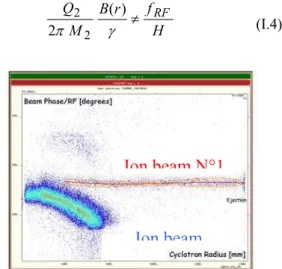
In the figure 1, the beam n°1 stays in phase with RF accelerating cavities while it is not the case for the beam n°2, we have
H f r B M Q RF ≠ γ π ) ( 2 2 2 (I.4)
Fig. 1: Phase measurement as function of the radius in CIME using a 300 µm silicon detector. Test realised with 36Ar (ions n°1) and 18O (ions n°2) on harmonic 3.
Let us note that by adjusting either the RF frequency or the magnetic field, the beam n°2 could fulfil the synchronism condition and thus be accelerated up to extraction of the cyclotron: This is the basic principle of the cyclotron’s tuning.
Hence, after the tuning of stable ion species, we can use either the magnetic field or the RF frequency to shift towards the correct tuning for the radioactive beam (or a combination of both).
It is hard to monitor large modifications of the magnetic field level, since it modifies the global configuration of the field inside the cyclotron, this effect would alter the isochronism. Furthermore, magnetic field variations are not completely reversible, and another strategy is most of the time
Ion beam N°1
preferred. Although the frequency shift (strategy b) can be realised with an accuracy below 10-7, a large modification of the frequency, which is needed to accelerate radioactive ions with a rather different mass over charge ratio, induces a modification of the revolution frequency at large radius. This isochronism defect is a pure relativistic effect coming from the radial dependence of γ factor :
(
)
1/2 2 2 2 1 − − = c r frev π γ (I.5)The isochronism, which guarantee optimum transmission, is altered. Therefore to restore the equality in eq.(I.4) over the whole acceleration process, B(r) should be theoretically modified with an accuracy around 10−5, which is not easy. So, it is important that the mass over charge ratio of the stable element used for the tuning is not too far from the desired radioactive ion in order to perform frequency shift which do not alter too much the isochronisms.
Numerous studies have demonstrated that the RF frequency shift (strategy b) is the most convenient and reliable method to pass from the tuning ion beam toward the radioactive ion beam. In harmonics 4 and 5 (2-6 MeV/A), the radioactive ion beam is ejected directly from the cyclotron after the frequency shift. For harmonics 2 and 3 (5-25 MeV/A), the ejection of radioactive beam is much more difficult since the large turn number coupled to a slight precession and to the relativistic effects make the trajectory of the radioactive beam different from the tuning beam. The case of 8He2+ at 15 MeV/A is the worst as we explain below.
Difficulties with
8He
2+Difficulties have been encountered in the very peculiar case of the acceleration 8He2+ around 15 MeV/A. Several reasons make it very difficult to extract 8He2+ from the cyclotron. We summarize the different origins of the difficulties :
1) The tuning has to be realised with a stable element whose mass over charge ratio M/Q is not to far from the one of 8He2+. In that we case, we have to choose 16O4+ which is polluted with a
12
C3+ ion beam and can prevent us to tune properly the cyclotron.
2) The emittance of helium ion beam in the low energy beam line can reach up to 150 π mm.mrd which is the worst case for the ECR ion source, leading to very poor transmission of the accelerator (10-15%).
3) The most convenient strategy to pass from the stable ion beam to the radioactive ion beam is the RF frequency shift. This strategy is not exact since the two ion beams will not describe strictly the same trajectory because of relativistic effect which become non negligible at 15 MeV/A. The difference between the two trajectories make the transmission at the extraction of the cyclotron very different for the stable ion beam and the radioactive
ion beam. It can occur that all particles get lost in ejection channels, imposing to search randomly the value of the 9 parameters of the ejection. As a result, the tuning time needed should be increased to adjust properly the ejection of the cyclotron.
A large part of the beam time allocated to the accelerator studies has been devoted to the understanding of the different problems. We have established that a minimization of the precession in the cyclotron and a perfect tuning of isochronism are of utmost importance to be able to eject 8He2+ with a good transmission in harmonics 2.
Mass purification
As far as the purification of very rare isotope is concerned the achievement of very good mass resolution is not sufficient. Since stable contaminants can dominate by several orders of magnitude the intensity of given radioactive ion species, it is of utmost importance to perform a very clean separation.
A given ion, with a mass M1 and charge
Q1, performs one turn in the cyclotron with a fixed
frequencyfrev. When the synchronism condition is fulfilled, the relative phase
φ
1 of the ions with theRF accelerating cavities stay constant altogether with the energy gain per turn 1
turn E ∆
,
which is given by ) cos(φ
1 RF turn V E ∝ ∆ (I.6)The ions are thus accelerated up to the ejection channel of the cyclotron. For another ion, with a different mass to charge ratio (M2/Q2), the
synchronism condition is not fulfilled, the relative phase φ2 with the RF system evolves up to φ2=90°,
and then these ions are not accelerated anymore (
∆
E
turn≤ 0) and get lost inside the cyclotron (see for instance Fig. 1, ions N°2). This mechanism allows the elimination of any undesired ion if the mass over charge ratio is such that its phase exceeds 90° before the end of the cyclotron. This condition corresponds at first order to:turn N H Q M Q M Q M π 2 1 1 1 1 1 2 2 < − (I.7) where Nturn is the number of turns. Hence
the mass resolution of a cyclotron is defined as
turn N H
R=12π
.
Depending on the harmonic, the mass resolution of CIME can reach 1.6 10-4.fig.2 : Transmission of CIME cyclotron as a function of the mass over charge ratio deviation.
The mass selection obtained experimentally, whatever the harmonic, is close to the one expected theoretically (fig 3). Besides the cyclotron ensure a very clean separation, since the ion contaminants with mass deviation greater than 5.10-4 are strongly suppressed : the transmission for these ions are smaller than 10-6 .
This study demonstrate that the nominal tuning, associated with the selectivity of the ECR ion source allow a total purification, provided that the charged state of radioactive ions are properly chosen. In the context of SPIRAL2, heavier ions (A>100) produced by non-chemically-selective sources could be accelerated with CIME. A much better mass resolution will be required to purify the beams. The possibility to achieve a resolution around 5.10-5 would be studied very soon.
II)
Beam line studies
Low energy beam line
Since the beginning of the SPIRAL operation, very large misalignment defects at the source extraction have been reported. During the first test period (2000-2001), several off-line beam’s reconstruction has confirmed a deviation of 10-20 mm from the axis in the horizontal plan at the exit of electrostatic lenses. Such a large misalignment prevent us to optimize the matching of radioactive ions at source extraction with the electrostatic Einzel lens which induced additive misalignment when corrections are applied. This fact is a strong limitation in operation since it is really important for the transmission of radioactive ions to match exactly the stable beam used for the tuning.
The origin of the misalignment has not been perfectly determined. Nevertheless, the magnetic fringe field of the source sextupole at the extraction region could explain such deviations. The replacement of the source system for each experiment does not allow to correct such a defect with a re-alignment of source system.
Therefore two additive steerers will be added in the beam line to compensate the large deviations observed.
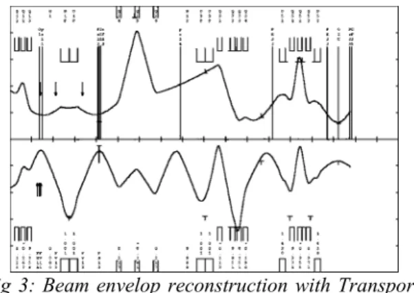
fig 3: Beam envelop reconstruction with Transport program in the low energy beam line
(
ε
x=
ε
y= 120
π
mm.mrd)
Medium energy beam line (CIME
ejection)
While we could expect theoretically at the exit of the cyclotron a transverse beam emittance of 5-10
π
mm.mrd, we often observe an emittance around 40π
mm.mrd in the horizontal plane. Such a large emittance figure could induce large beam loss in the Z spectrometer and is not suitable for a lot of physics experiments.Actually, the beam envelop is dominated by a chromatic effect, indeed, particles with different momentum will not follow the same trajectory, increasing a lot the size of the beam. Let us underline that the dispersion vary a lot from one setting to another since the whole energy range of the cyclotron is quite wide (from 1.7 to 25 MeV/A). Therefore the momentum dispersion is still not perfectly known, and the computed optics of the medium energy line do not permit the compensation of momentum dispersion. The measurement of the momentum dispersion is far from obvious and do not allow to re-compute easily the optics to correct the defect, and on-line adjustments are needed to minimize the beam size. Tedious optimization of quadrupole settings permit to reach 15-20
π
mm.mrd in the horizontal and the vertical plane.Efforts have been made to decrease the tuning time and guarantee the reproducibility of the operation. A software has been develop allowing the fast optimization of the beam intensity in a given emittance.
III)
SPIRAL operation with new
softwares
The operation of SPIRAL accelerator and beam lines has benefited from the development of large number of software components for GANIL accelerator. Indeed, lot of time consuming tasks can be realised in-line automatically (beam centring, betatron matching, isochronisms, achromaticity) thanks to different beam detectors (profile
monitors, beam central phase probes,…) and the associated control system. Most of software programs have been adapted for the operation of SPIRAL, but the specificity of the CIME cyclotron and new scientific request leads us to upgrade and develop new software programs.
Computer aided on-line optimisation The tuning of SPIRAL is generally a time consuming task, since optimum transmission is required with the scarce radioactive ions. During the first year ofSPIRAL, we realized that the time needed to optimize beam transmission through the accelerator is hardly compatible with the different operational constraints. The good transmission figures in the cyclotron have been obtained after careful tunings and painful optimizations.
A new computer program based on a steepest descent algorithm has been developed. Object programming concepts have been implemented to open up the possibility to optimize any function of different beam diagnostics with a large variety of equipment. The basic algorithm can be summarized as follow :
-Start with set of accelerator parameters (P1,..PN) and measure on a diagnostic the function to optimise I(P1,…,PN), typically a beam intensity.
- Compute the gradient ∇I(P1,…,PN) ,by measuring successively
I(P1+
ε,…,PN),
…. I(P1,…,PN+
ε).
-
Search the optimum in the direction of the gradient ∇I(P1,…,PN). And restart with the new set of parameters (P1’,…,PN’).An important literature is devoted to the mathematical problem of function’s maximisation (or minimisation). For instance, we can ensure a better convergence of the algorithm by an orthogonalisation of the successive directions of optimization (conjugate gradient method in multidimension). Let us underline that the mathematical details of the optimization to speed up the convergence are less important in this context than the robustness of the algorithm. One of the main problem is to get reliable measurements. Averaging with several measurements in order to smooth non-significant fluctuations is needed. Moreover, the increments ε to be applied on the set of accelerator parameters should be carefully chosen to compute the gradient ∇I(P1,…,PN).
The implemented algorithm allows the optimization of the beam’s transmission beam at the injection of the cyclotron with 20 parameters within 3 minutes. We use it to optimise the cyclotron ejection region, and also to decrease the chromatic horizontal emittance in the medium energy beam line. Let us note that the optimization stage do not replace the tuning stage but permit us to get better transmission, and a better beam quality in a reasonable time interval
.
“Fast” Energy variation
Different physicist requests have underline the scientific interest to change as fast as possible the energy of the beam downstream of the cyclotron. Conversely to a tandem or a linac, the energy variations with a cyclotron like CIME are really difficult since all the magneticfields, electric fields and RF frequency of RF cavities have to be rescaled.
The tuning of the cyclotron and beam lines for a given ion beam at given energy required 16-24 hours. Starting from beam well tuned in the cyclotron, we aim to modify the set-up in order to accelerate the same beam with a slight different energy (±20%) within 4 hours. Generally, a set of theoretical cyclotron parameters Ptheo (M1,Q1,E1)
computed to accelerate an ion beam (M1,Q1) at the
energy E1 has to be adjusted empirically to deliver
the beam with good transmission. The difference
∆P
Theo-Expbetween the theoretical parameters and
the experimental ones take account of the hysteresis in the magnet, temperature, misalignment, equipment defect.
The extrapolation of the cyclotron tuning from one energy to another is performed as follow
P
Exp(M
1,Q
1,E
2) = P
theo(M
1,Q
1,E
1)+
∆P
Theo-Exp(E
1) .
Numerous tests have been realized and it appears that energy variations can be realized rather quickly, within 4 hours. A loss in transmission around 50% is, nevertheless often observed. If an optimum transmission should be recovered, 8 hours has to be spent.
The developed software performs the extrapolation task of the tuning parameters from one ion beam (M1,Q1,E1) toward another ion beam
(M2,Q2,E2). Besides the software has been
implemented also to handle the different strategies to pass from the tuning ion beam toward the radioactive ion beam as explained in chapter I.
CONCLUSION
The most remarkable result with the cyclotron is the good transmission in the whole energy range, from 1.7 to 25 MeV/A (Tab.1).
H (Har-monic) Number of turns Transmission with stable ions Beam quality 2 330 ~ 30% 3 280 30-40% 4 120 30-35% 5 100 15-20%
εx~
15πm m.mrd ∆E <0.005 ETab. 1: Cyclotron transmission, for beams included in 80 π mm.mrd.
During the first year operation of Spiral with radioactive beams, our efforts have been
focused to improve our ability to deliver any ion beams with a good accelerator transmission with a correct beam quality within a reasonable time interval.
Some works is still needed to improve our flexibility in the delivery of different ion beams.
Several aspects will need more work to improve the beam qualities: a systematic study in
the whole energy range of the cyclotron is still required for the understanding of the chromaticity in the medium beam line which is related to the observed horizontal emittance. Besides better understanding of the beam’s matching in the injection line will be necessary to improve the beam quality.
2.3 Energy range extension of the CIME centres
F. Chautard
Introduction
The cyclotron CIME has an axial injection system, which let the possibility to accelerate ion beams from 1.7 to 25 MeV/u at the RF harmonics1 H=2,3,4,5. However, two different centres are needed to cover such a large energy range:
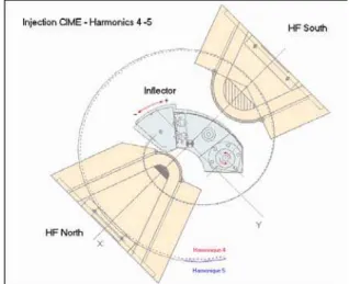
The low-energy beams, from 1.7 to 6.2 MeV/u, are injected at a radius R=45 mm, using a Pabot-Belmont inflector, and accelerated on RF harmonics 4 or 5 (fig 1).
Figure 1: CIME central region for the harmonics 4 and 5. Composed of two RF extremities and a SPIRAL inflector followed by an electrostatic quadrupole. The trajectory of a reference particle is depicted.
The High-energy beams, from 4.9 to 25.4 MeV/u, are injected at a radius R=34 mm, using a Muller inflector complemented by an electrostatic quadrupole and accelerated on RF harmonics 2 or 3 (fig 2).
1
Radio-Frequency Harmonics : ratio between the frequency of the acccelerating cavities and the ion revolution frequency in the cyclotron. Practically, the Harmonics corresponds to the number of ions bunches per turn in the cyclotron.
Figure 2 : CIME central region for the harmonics 2 and 3. Composed of two RF extremities and a MULLER inflector.
For the two energy domains, special dismountable extremities of the RF cavities have been designed to optimise the transit time at the injection.
The exchange of these two centres, inflector and RF cavities extremities, requires a 2 days intervention. This time consuming task represent an additive operational constraint of SPIRAL. Practically, we cannot deliver successively a high energy beam and a low energy beam during the same SPIRAL run. Moreover, in the context of Spiral2, the strong activation of the inflector could forbids any handling during long period. Therefore, there is a strong interest to enlarge as much as possible the energy range of each centre.
Simulations have been undertaken to evaluate the parameters which allow the injection and the acceleration of the beam in the cyclotron centre. These simulations allowed the determination of the beam injection energy. Then, the platform voltage and the magnetic rigidity (Βρ) of the transport line can be deduced. Values of the isochronism coils are computed with the suitable centre considering that the isochronism law is identical for a given frequency (same beam energy) and field level.
The value of the two first isochronism coils, B1 and B2, which determine the magnetic field in the cyclotron center are not obvious to evaluate. A careful multiparticle simulation help us to compute the optimum magnetic field configuration.
Given that the geometry of RF cavity extremities is different from one centre to another (fig. 1 and 3), the values of these 2 coils have to be modified. Hence, the value of the two first isochronism coils are adjusted as a function of the field level and the RF harmonic, to bring the beam in phase in the first cavity gaps.
1. Acceleration in H3 with the “45 mm
centre”
Preliminary simulations have shown that it was possible to accelerate a beam under these conditions. It is possible, from parameter values of isochronism coils and the main field computed for the harmonic 3 with the centre 34 mm, to accelerate a beam with the centre 45 mm. Simulations show the necessity to increase RF voltage to accelerate the beam through the first gaps. The maximum voltage of the RF cavity and the source platform represent the limitation to extend the limits of this centre towards the high energy (fig. 3)
The test performed with 16O4+ Ion beam at 6.0 MeV/A have been successful. CIME yields with opened emittance slits (> 200 pi.mm.mrad) are correct.
Yields obtained after 4 hours tuning (see parameters in Annexe):
IC_CF13 IC_CF35 IC_CF81 L5_CF11 [µA] [µA] [µA] [µA] 1,63 1,33 1,2 0,40
The yield between the injection and the CIME ejection is 33 %.
2. Acceleration in H4 with a “34 mm
centre”
To complete the study, we have to evaluate the acceleration of a beam in harmonic 4 injection centre initially dedicated to the harmonic 2 and 3. The simulations allowed the determination of the injection energy at 34 mm. It is possible, from parameter values of the isochronism coils and the main field computed for the harmonic 4 with the centre 45 mm, to accelerate a beam with the centre 34 mm.
The test performed with 40Ar6+ ion beam at 5.18 MeV/A have been successful.
Yields obtained after a 4 hour tuning :
IC_CF13 IC_CF35 IC_CF81 L5_CF11 [µA] [µA] [µA] [µA] 0.650 0.632 0.557 0.205
The yield between the injection and the CIME ejection is 31 %. The yields of CIME with opened emittance slits (> 200 pi.mm.mrad) are in the order of the optimum tuning with the other injection centre.
Let us mention that a limitation exists : We cannot reach with this injection radius the very low energy region since it would need a very low injection energy. The minimal source platform voltage has been arbitrarily fixed to 10 kV. Below this value, the space charge effect becomes non negligible and important beam quality degradations would alter the beam transmission. Therefore only a fraction of the energy in H4 as a function of the Q/A is accessible (fig. 4).
3. General Conclusions
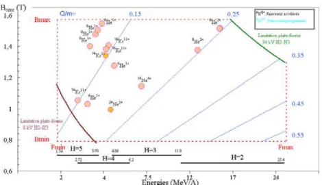
It has been shown that it is possible to reduce the number of change of centre with equivalent efficiencies. The Figure 5 shows that all accelerated beams up to now might have been accelerated with a centre H2-H3 and a voltage platform between 34 kV and 8 kV.
In the next year, the possibility to accelerate the beam in the harmonics H=6 will be studied to enlarge the energy range toward the low energy (> 1.2 MeV/u).
Figure 3 : New accessible energy range with the centre H4-H5
Figure 4 : New accessible energy range with the centre H2-H3
Figure 5 : SPIRAL beams accelerated from November 2001.The min max limitation of the platform voltage are plotted.
Annexe: Simulation’s result
For historical reasons simulations with theprogram lions (ref : GANIL R 93 08) must be done at a beam revolution frequency of 4.8 MHz. Which corresponds to 14.4 MHz for H3 and 19.2 MHz for H4.
A) Acceleration in H3 with the “45 mm centre”
According to the simulations at 14.4 MHz and H3: Ion : 16O4+, Q/A = 0.25
Injection energy = 10.73 keV/A
Source voltage = 16 * 10.73 / 4 = 42.9 kV Cavity voltage = 85000 V
From these calculated parameters we choose a beam of interest in the frequency range.
Beam and parameters selected :
Ion : 16O4+, Q/A = 0.25; H = 3 RF Frequency = 10.66 MHzInjection energy = (FHF/14,4)**2 * 10.73 = 5.88 keV/A
Source voltage = (FHF/14.4)**2 * 42.9 = 23.52 kV CIME ejection energy = 6 MeV/A
Transport line (TBE) magnetic rigidity = 0.04415 T.m
RMN value at the CIME north sector = 12213 G (BP = 931 G)
Cavity voltage = (10.66/14.4) * 85000 = 63 kV
B) Acceleration in H4 with a “34 mm centre”
According to the simulations at 19.2 MHz and H4 : Ion : 40Ar6+, Q/A = 0.15
Injection energy = 5.814 keV/A Source voltage = 40*5.814/6=38.7 kV Cavity voltage = 83300 V
Beam and parameters selected : Ion : 40Ar6+, Q/A = 0.15; H = 3 Frequency FHF = 13.22 MHz
Injection Energy = (FHF/19.2)**2 * 5.814 = 2.75 keV/A
Source Voltage = (FHF/19.2)**2 * 38.7 = 18.4 kV CIME ejection energy = 5.187 MeV/A
Magnetic rigidity = 0.0503 T.m
RMN value at the CIME north sector = 18955 G Cavity voltage =(FHF/19.2)*83300=57 kV
Experimentally, the applied tension is closer to 80 kV than 57 kV that implies less turn in the cyclotron in order to pass the first RF gaps.
3
TECHNICAL
DEVELOPMENTS
3.1 A cryogenic target for secondary ion beams
P. Dolégiéviez, Ph. Robillard, M. Ozille
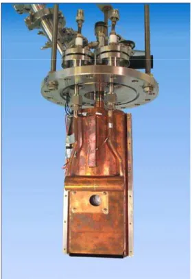
A cryogenic system has been designed to make a thin target of solid hydrogen usable under vacuum, with a particle beam. This document describes the system developed and presents the results obtained with a 1 mm thick target with a diameter of 10 mm used with the first beam of SPIRAL facilities.
INTRODUCTION
The development of solid phase hydrogen targets is part of the research program with secondary ion beams [1]. The main requirements imposed for such targets are: low thickness, very fine windows, and uniform thickness and density.
Target systems have already been designed in various laboratories, particularly by directly condensing H2 gas to make the target [2,3]. In the
system developed, we opted for a transition to the liquid phase (16.2K / 23 kPa) before progressive solidification of the hydrogen (T< 13.9K ) [4].
Liquid helium is used as a cold source at 4 K and the growth of the target is imposed by the temperature gradient in the metal frame supporting the target.
DESCRIPTION OF THE SYSTEM
Principle
The target is made using a metal frame to which mylar windows are glued. A stack of frames forms an H2 target cell with an He cell on either side of the
target.
During the target production phase, equivalent pressure is maintained on either side of the target windows. To do this, the pressure of a volume of helium gas matches the pressure variations of the hydrogen circuit during the phase transitions and up to the complete formation of the solid H2 target
(Figure 1). Once the target is formed, the helium gas is evacuated. The mechanical strength of the windows of the He circuit with respect to beam vacuum imposes the filling pressure, and hence the phase change temperature of the target gas.
Cryogenic system
The cryogenic system consists of a cryostat with liquid helium circulation, of which the cold thimble (T = 4K) is mechanically coupled with the lower part of the target. This configuration helps to establish a temperature gradient aimed to make the solid grow towards the upper portion of the target. The gases enter through stainless steel capillaries (Φ 1-2 mm) welded at the bottom of the target for He and at the top for H2. A thermalisation point is used from the
cold thimble to reduce the power input by conduction of the capillaries at the top of the target. However, to prevent clogging, the H2 circuits are kept at T>14 K
during the target filling phase. This condition is essential to prevent the formation of bubbles caused by a lack of hydrogen feed during the formation of the solid.
The heat balance of the system gives a power received at the target of about 10 mW, 50% of it from thermal radiation (opening up the target to the beam axis). The heat transfer analysis reveals the
possibility of obtaining the desired growth of the solid, by using brass (intermediate thermal conductivity) and by adopting a suitable geometry for the target frame (Figure 2). This solution offers a compromise between the cooling of the target and the
maintenance of the hydrogen gas in the capillaries in the gas phase.
∆P ~
Beam
vacuu
H
2He
Mylar
Metal
Cold
Calculations were made to determine the effect of the power deposited by the particle beam on the cryogenic target. With the beams used, the temperature elevation at the target remains negligible. The limit above which the triple point of H2 is approached appears to lie around 10mW for a
4 mm diameter beam [5]
For the remainder of the system, a liquid nitrogen circuit ensures the thermalisation of the capillaries of the target at 80 K as well as the cooling of a shield to limit the radiation towards the device. The change in temperature in the system is monitored by silicon diodes. The overall vacuum system is supported by a stainless steel flange to vacuum standard DN 160 ISO-K (Figure 3).
Results
The results were obtained with a 1 mm thick target and 6 µm mylar windows. The observation of solid growth showed that as the temperature drops, the temperature gradient allows for the presence of the three H2 phases in the target. The H2 targets
produced display no visible defect (Figure 4). The time required to produce the solid target, after
placing the cryostat under vacuum, is about 3 hours and the system consumes ~1 l/h. of liquid helium to maintain the solid target at low temperature (depending the vacuum level).
The target was placed in the experiment vessel to intercept the beam during near a week (Ne 18 / P~20 µW on the target) and during all the
experiment, the target temperature has stayed below 9K.
REFERENCES
[1] W. Mittig and P. Roussel-Chomaz : Results and Techniques of Measurements with Invers Kinematics, Nuclear Physics (2001) A 693 495-513.
[2] P.E. Knowles, et al. : Nucl. Instr. and Meth (1996) A 368 604
[3] S. Ishimoto, et al. : A Windowless Solid Hydrogen Target, June 2000 KEK preprint (2000)-23 H
[4] P. Dolégiéviez, Ph. Robillard, Ph. Gallardo, M. Ozille, D. Heuze : Cryogenic system for a thin solid hydrogen target, November 29,(2000) Report Ganil A 00 01
[5] M. Ozille : Ganil report (2002)
Figure 4 Hydrogen target : solid growth Figure 3 Overall view of the device with 80 K shield
35
3.2 EFFICIENCY AND PRODUCTION YIELD MEASUREMENTS OF
RADIOACTIVE O, N AND F FOR THE SPIRAL FACILITY
S. Gibouin, ACC. Villari, JC. Angelique, O. Bajeat, F. Bocage, JM. Casadjian, S. Essbaa, G. Gaubert, Y. Huguet, A. Joinet, P. Jardin, S. Kandri, A. Khouaja, F. Landre-Pellemoine, C. Lau, N. Lescene, H. Lefort, R. Leroy,
C. Marry, L.Maunoury, D. Nayak, JY. Pacquet, MG. Saint-Laurent, C. Stodel
Production efficiencies of radioactive oxygen and nitrogen beams for the SPIRAL target-source system, measured at GANIL on the SIRa test bench, are presented. From the overall efficiency of oxygen, the product between the efficiency of transformation of O into CO and the effusion of CO from the target to the ion source, was deduced. The production yield measurements of oxygen and nitrogen isotopes performed on the SIRa test bench and those of fluorine directly measured on the SPIRAL facility are presented.
1. INTRODUCTION
Based on isotope separation on-line (ISOL) [1], the SPIRAL facility [2] at GANIL
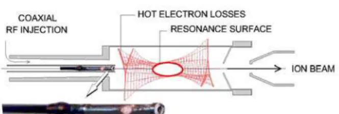
delivers beams of radioactive isotopes. These isotopes are produced by fragmentation of a stable primary beam in the SPIRAL target, diffuse out of it and effuse up to an electron cyclotron resonance ion source (ECRIS), where they are ionised. After their extraction from the source, the radioactive isotopes are selected by a separator magnet before being injected into the cyclotron CIME [3] to get medium energy ions. The first radioactive beam (18Ne4+), corresponding to the commissioning of the SPIRAL facility, was sent to the experimental area at the end of September in 2001 [4]. The present target-source [5] system can supply radioactive beams of noble gases, with a dedicated target for He and another one for Ne, Ar and Kr. Furthermore, gaseous isotopes or molecules produced in the target could also be efficiently transported to the ion source, which would allow ionising and post-accelerating alternative radioactive beams.
In particular, oxygen and nitrogen radioactive beams are presently of great interest, mostly for astrophysics, e.g. 15O(α,γ)19
Ne [6] and direct reactions studies, e.g. 13N(p,t)11N [7]. The SPIRAL carbon target produces important amounts of oxygen and nitrogen molecules (CO, CO2, CN, etc.) allowing a fast transfer from the target to the ion source. This phenomenon is well known and was already used to produce radioactive beams at LISOL [8] and more
recently at CRC, Louvain-la-Neuve [9]. For a more detailed review of ISOL oxygen beams, see reference [10]. Finally, the oxygen and nitrogen molecules are efficiently ionised in the ECRIS, which is the SPIRAL ion source [11]. Therefore, all ingredients necessary for an efficient production of
these elements are present in the SPIRAL target-ion source system.
In this paper, we present the results of production efficiency and production yield measurements of radioactive O and N beams measured at the SIRa [12] test bench, and the production yield of radioactive F directly measured in the SPIRAL production cave. The expected production rates on the SPIRAL facility are also given.
2. EXPERIMENTAL SET-UP
The production efficiencies and production yields of radioactive oxygen and nitrogen beams have been measured on the SIRa [12] test bench at GANIL with the target-source system already developed for the production of radioactive neon, argon and krypton. The target, shown in Fig. 1, is made of a 1 µm graphite microstructure (POCO Graphite industries) in a conic shape with slices of 0.5 mm spaced by 0.8 mm, linked by an axis. It can be heated up to 2450 K by sending a current through its axis (the evaporation rate of carbon becomes important for the target above this temperature) to get a fast diffusion of the produced radioactive isotopes. The target is connected to a compact full permanent magnet ECR ion source (NANOGAN3 [13]).
The connection between the target container and the ion source is at room temperature.
Therefore, for very reactive elements like oxygen, nitrogen and fluorine, the transport of the radioactive species is possible only if volatile molecules would be synthesized. The chemical nature of the target (carbon) plays an important role in this case.
The overall efficiency ξ of the production
processes can be described, for example, for the reactive element O and for this target-source system, as follows :
36
ξO = ξO-CO . ξdiff(CO) . ξeff(CO) . ξion(O/CO) .ξtrans(O) (1)
The right hand terms of equation (1) respectively represent the transformation efficiency of O into CO, the diffusion efficiency of CO, the effusion efficiency of CO, the ionisation efficiency of O coming from CO and the transport efficiency of O. The product ξdiff(CO) . ξeff(CO) is lifetime and
temperature dependant, but this is not the case of the product ξion(O/CO) . ξtrans(O).
For the overall efficiency measurements, we simultaneously implanted secondary 14O and
13
N beams, produced by projectile fragmentation using the SISSI device [14,15], in the target of SIRa. The implanted 14O and 13N were identified and quantified by Time-Of-Flight with a plastic detector placed just before the target. Non-ambiguous identification of 14O and 13N were provided at the end of the test bench, by the detection of the 2312.6 keV gamma ray for the first element and the 511 keV rays from
β
+ annihilation for the second one, by using a germanium detector. The overall efficiency for each isotope is given by the ratio between their measured quantities at the end of the test bench and those implanted in the production target. For the production yield measurements, we directly bombarded the SIRa production target with a 16O beam of 95 A.MeV. The quantities of14
O, 15O and 13N were measured, after selection by the separator magnet, at the end of the test bench.
3. EXPERIMENTAL RESULTS 3.1 Efficiency measurements The different contributions to the overall efficiency of 14O beam production for a target temperature of 2000 K was investigated by measuring the intensities of each molecular compound, as represented in Fig. 2. We assume that the 14O implanted in the target was released under the molecular form CO (due to the
enormous quantity of carbon atoms compared with others impurities). The other molecules were presumably created in the plasma of the ion source by a chemical reaction with mainly hydrogen, nitrogen, water, etc. The overall efficiency of 14O found in all charge states and any molecular compounds was equal to 6.5(4) %.
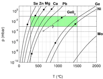
The overall efficiency of 14O beam production, as a function of the target temperature, was also investigated. These measurements are shown in Fig. 3. We can observe that around 2000 K a production plateau is reached. Therefore, one may conclude that for 14O (T1/2 = 70.6 s) the
diffusion efficiency reached 100 % at this temperature. Concerning effusion, this is not the case, mainly because the transfer between target and ion source is cooled.
Moreover, we performed complementary off-line measurements on the ionisation efficiency of O coming from CO. In this study, a known quantity of stable 13C16O was injected through a alibrated valve. The quantity of ionised 16O (including molecular forms) was measured at the end of the separator magnet. The ratio between these two quantities represents the ionisation efficiency of
16
O coming from 13C16O, so-called
ξion(16O/13C16O). The ionisation efficiency of 13C coming from 13C16O, so-called ξion(13C/13C16O), was also measured and found approximately similar. Therefore, we assumed that both ionisation efficiencies are equivalent, i.e. ξion(13C/13C16O) = ξion(16O/13C16O) =
ξion(14O/12C14O) (2)
Considering a total beam transport efficiency of 53(5) % - also measured off-line using a 40Ar calibrated leak - we obtained
ξion(16O/13C16O) = ξion(14O/12C14O) equal to
29(9) %. Finally, one can conclude that for 14O (T1/2 = 70.6s) at 2000 K, the product between the
transformation efficiency of O into CO and the effusion efficiency of CO between target and ion source is:
ξ14O-12C14O .ξeff(CO) = 42 (13) % (3)
Similarly, the overall efficiency for ionisation of
13
N was also measured at 2000 K. We obtained 0.67(5) % for 13N1+, 0.047(8) % for 13N3+, 0.048(5) % for 12C13N+ and 0.032(11) % for
13
N16O+. In the case of nitrogen, the CN molecule is not an inert molecule at room temperature like CO. Therefore, the transport of radioactive nitrogen is less efficient.
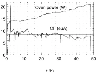
3.2 Expected production rates on SPIRAL The production yields of 14O, 15O and 13N were measured at the SIRa test bench
impinging a limited intensity of 0.25 pµA of a 95 A.MeV 16O primary beam (corresponding to 380
37
W) directly on the carbon target, heated at about 2000 K. The average production ratesobtained during 2 days of irradiation are presented in Table 1. From these results, we extrapolated the production rates for SPIRAL supposing a maximum beam power of 1500 W of a suitable primary beam (cf. Table 1). A 50 % transmission factor of the SPIRAL separator was assumed, provided that the correct adaptation of the beam to the injection of CIME imposes beam losses. It should be noted that the intensities obtained on-line are in perfect agreement with the estimations using the EPAX [16] model and the efficiencies measured in the preceding session.
18
F production yields were also directly measured on the SPIRAL facility by impinging 0.2 pµA of a 95 A.MeV 20Ne primary beam on the SPIRAL target. We obtained 2 x 10⁵ p/s at the exit of the CIME cyclotron, corresponding to around 8 x 10⁵ p/s just after the ion source. It is expected that with a 1500 W primary beam of
19
F, the final production rate of 18F will be around 1 x 10⁶ p/s.
4. CONCLUSION
In the framework of SPIRAL developments, the production efficiencies and production yields of radioactive O and N beams have been studied on the SIRa test bench. The overall efficiency measurements of oxygen and nitrogen have been presented, indicating that many molecules are created not only in the target zone but also in the plasma of the ion source. The efficiency of
14
O beam production as a function of the target temperature has been determined and its saturation was observed at 2000 K. Finally, the product between the efficiency of transformation of O into CO and the effusion of CO from the target to the ion source has been deduced. This mechanism is responsible for an efficient transport of oxygen from the target to the ion source plasma.
Production yield measurements of oxygen, nitrogen and fluorine isotopes have been presented. The expected production yields for SPIRAL have been extrapolated. The yield measurements are in perfect agreement with theoretical calculations using EPAX model folded by the efficiencies measured in this paper.
(1) Technical drawing of the Target-Part of the SPIRAL Target-Source production system. The target used for the production of radioactive Ne, Ar and Kr beams is shown.
38
(2) Different contributions to the overall efficiency of 14O measured on the SIRa test bench, for a target temperature of 2000 K. The intensity of the 12C14O16O+ molecule is not represented because its quantity is negligible compared with 12C14O+.
(3) Overall efficiency of 14O1+, 14O3+ and 12C14O1+ on the SIRa test bench as a function of the target temperature. A line is drawn to guide the eye.