HAL Id: in2p3-00024264
http://hal.in2p3.fr/in2p3-00024264
Submitted on 17 Jun 2005
HAL is a multi-disciplinary open access
archive for the deposit and dissemination of
sci-entific research documents, whether they are
pub-lished or not. The documents may come from
teaching and research institutions in France or
abroad, or from public or private research centers.
L’archive ouverte pluridisciplinaire HAL, est
destinée au dépôt et à la diffusion de documents
scientifiques de niveau recherche, publiés ou non,
émanant des établissements d’enseignement et de
recherche français ou étrangers, des laboratoires
publics ou privés.
Technical report on operating accelerators 2003-2004
E. Petit, A. Savalle, F. Chautard, P. Anger, P. Bertrand, F. Daudin, M. Di
Giacomo, B. Ducoudret, M. Duval, P. Lehérissier, et al.
To cite this version:
E. Petit, A. Savalle, F. Chautard, P. Anger, P. Bertrand, et al.. Technical report on operating
accelerators 2003-2004. 2005, pp.1-96. �in2p3-00024264�
Grand Accélérateur National d’Ions Lourds
Laboratoire commun CEA/DSM - CNRS/IN2P3
GANIL R 05 01
TECHNICAL REPORT
ON OPERATING ACCELERATORS
2003 – 2004
Fig. 1 Fig. 2CONTENTS
page
Foreword
3
Préface
4
1. ACCELERATOR OPERATION:
- Accelerator operation in 2003 and 2004
7
- Evolution of operation since 1996
13
2. MACHINE STUDIES:
- Summary of machine studies in 2003 and 2004
19
- CIME Harmonic 6 studies
21
3. TECHNICAL DEVELOPMENTS:
- The CICS Project
29
- Improvement of the mass separation power of a cyclotron by
using the vertical selection method
33
- Improvements on stable beams from ECRIS
37
- LINUX migration of the GANIL control system
43
4. EVOLUTION OF THE FACILITY:
- The new high voltage platform of the injector C01: PFI1 project
51
- LIRAT: a new low energy beam line for radioactive ions
59
5. APPENDIX#1:
- Experiments conducted in nuclear physics – year 2003
65
- Experiments conducted in nuclear physics – year 2004
69
- Experiments conducted in swift ion physics – year 2003
73
- Experiments conducted in swift ion physics – year 2004
75
- Available ions at GANIL
77
- Accelerated beams with their characteristics
79
- SPIRAL beams : Radioactive ion beams intensities
83
6. APPENDIX#2: List of publications
- Articles
87
- Conferences
89
- Preprints
93
- Reports
95
Cover page :
Fig.1 : LIRAT beam line view
FOREWORD
This issue of the Technical Report about the Accelerators describes the operation
for physics experiments and beam tests, various technical improvements and projects for
the years 2003-2004.
As usual the first chapter reports on the standard operation of GANIL with stable
as well as radioactive beams, an analysis of the beam time distribution and statistics. Then
there is a status report and an analysis of operation since 1996.
The second chapter, dedicated to beam tests, illustrates the importance of beam tests
improving the performances concerning the delivery of radioactive beams. Great efforts
have been made, firstly with stable beams, through THI beam tests and beam dynamic
studies, and secondly with radioactive beams, through radioactive-ion production tests and
the extension of the CIME working diagram.
Technical studies, essentially concerning ion-source developments on stable metallic
beams and technical improvements to the accelerators , are described in chapter 3.
The last chapter deals with the installation of the new high-voltage platform of the
injector C01 at the beginning of 2004 (PFI1 project).The aim of this project is to increase
beam intensity at extraction from this new platform, especially for metallic ion beams, and
to ensure a better stability with the high-intensity beams produced. The first results,
obtained in beam operation during 2004 , are promising. In this last chapter a status
report is given on the very low energy beam line for radioactive beams line, called LIRAT.
This new facility has been commissioned in mid-2004 with stable beam. The last step is to
obtain the permission from the Nuclear Safety authorities to expand the LIRAT operation
to radioactive ions, which we hope to receive at the beginning of 2005. This will allow us to
use radioactive beams produced with the SPIRAL target -and-source device directly, and
thus to offer new possibilities for physics.
Eric PETIT
PREFACE
Ce numéro du rapport technique des accélérateurs décrit le fonctionnement pour la
physique, les études machine, les améliorations techniques et les projets pour la période
2003-2004.
Le premier chapitre décrit comme il est de tradition le fonctionnement des
accélérateurs avec des faisceaux d’ions stables mais également radioactifs, l’analyse de la
distribution du temps de fonctionnement et les statistiques. Puis dans ce premier chapitre,
un bilan et une analyse sont faits du fonctionnement des accélérateurs depuis 1996.
Le second chapitre, consacré aux études machine réalisées durant ces deux années, met
en évidence la place importante faite aux études pour l’amélioration des performances
dans le cadre de la fourniture des faisceaux radioactifs. Les efforts ont été portés tout
d’abord côté faisceau primaire, avec des études machine THI et des tests d’optique
faisceau, puis côté faisceaux radioactifs avec les mesures de taux de production en
faisceaux radioactifs et l’étude de l’extension du diagramme de fonctionnement de CIME.
Au chapitre 3 sont évoqués les développements techniques avec les
développements pour la production des ions métalliques sur les sources ECR en faisceau
stable, mais également les développements et améliorations côté accélérateurs (trieur
vertical dans CIME, projet CICS, la migration du commande-contrôle vers LINUX).
Le dernier chapitre décrit la mise en place, au début de l’année 2004, de la nouvelle
configuration de la plateforme source de l’injecteur 1 (projet PFI1). L’objectif visé est
d’augmenter l’intensité du faisceau à la sortie de cette plateforme, notamment pour les
faisceaux métalliques, et de garantir une stabilité plus grande sur les faisceaux haute
intensité produits. Les premiers résultats obtenus en exploitation sont prometteurs. Ce
dernier chapitre est également l’occasion de faire le point sur la nouvelle ligne d’ions
radioactifs très basse énergie, appelée LIRAT, qui a été testée avec succès en faisceau
stable au cours de l’année 2004. La dernière étape à franchir est l’obtention de
l’autorisation d’exploitation en faisceaux radioactifs de cette nouvelle ligne. Cette
autorisation est espérée pour le printemps 2005, ce qui permettra d’utiliser directement les
faisceaux issus de l’ensemble Cible/Source de SPIRAL et offrira ainsi de nouvelles
possibilités pour la physique.
Eric PETIT
1
ACCELERATOR
ACCELERATOR OPERATION
In 2003 and 2004
A. Savalle
1) Highlights
2003
The accelerator operation was 35 weeks long, in 4 periods. This represents 5604 hours of
operation. Among these 5604 hours, 3766 (67% of operating time) were used by physics
experiments. This is a record since the beginning of GANIL in 1983.
Since the beginning of SPIRAL operation, SISSI was unavailable due to technical
modifications and waiting for the safety authority authorization
.This authorization was
received in September and an experiment has been realized in October.
In parallel of high energy physics, about 240 hours of low energy beams (Xe, Pb, Kr) were
available for users of the IRRSUD facility.
Several problems occurred during the SPIRAL beams :
•
The production rate was too low for an experiment planned with
24Ne beam
•
Important failures during
8He beam (CIME deflector, EINZEL lens at the
source extraction, diagnostic failures...).
2004
The accelerator operation was 34.5 weeks long, in 5 periods. This represents 5532 hours of
operation. Among these 5532 hours, 3352 (60.7% of operating time) were used by physics
experiments.
In parallel of high energy physics, about 650 hours of low energy beams (Xe, Pb, Kr) were
available for users of the IRRSUD facility. The Intermediate energy exit delivers about 1400
beam hours per year for atomic physics.
The high voltage platform, where is located the ECR source for C01 injector, was unavailable
from march to may due to a major modification : a solenoid and a dipole have been included
to separate ions and charge state before acceleration. The result is a better stability, better
transmission in the cyclotron, and lower charge states needed for the same energy (the total
acceleration voltage, source extraction + acceleration tube, is now equal to 100 kV).
Let us notice, since this modification, the following results :
-
acceleration of 3 kW
13C beam for SPIRAL
-
acceleration of 1.2 kW
78Kr beam for SPIRAL
-
acceleration of 0.7 kW
48Ca beam for SPIRAL and SISSI
A new SPIRAL target, designed for 3 kW primary beam, was tested with the production of 6
10
5pps
8He
1+2) Accelerated beams
2003
Stable beams
SPIRAL BEAMS
Ion Energy (MeV.A) INTENSITY (PPS)
24 Ne 4.7 2 105 74 Kr 4.6 1.5 104 8 He 15 .4 1.5 104 8 He 15 .4 9 103 24Ne 10 2 105 8 He 15 .4 2.5 104
Period Ion Energy (MEV.A) Accelerator THI
1 32
S
95 SSC2 0.75 kW (D3) 1 36S
77.5SSC2
0.6 kW (D3)
1.4 kW (SPIRAL)
1 78 Kr 73 SSC2 1 36Ar
95SSC2
1 kW (SPIRAL tests)
1 112 Sn 63.5 SSC2 1 13 C 60SSC2
2 13 C 75 SSC2 1.4 kW (SPIRAL) 2 208Pb
4.5 and 29SSC1 and SSC2
2 238U
6.6SSC1
2 86 Kr 6.6 and 43.1SSC1 and SSC2
2 20 Ne 12CIME
2 238U
5.9SSC1
2 13 C 75SSC2
1.4 kW (SPIRAL) 2 129Xe
7.5 and 50SSC1 and SSC2
2 36S
11 and 77.5SSC1 and SSC2
0.5 kW (D3)
3 129Xe
50SSC2
3 208Pb
4.5SSC1
3 36S
77.5SSC2
1.4 kW (SPIRAL) 3 40Ar
4.8CIME
3 58Fe
5SSC1
3 36S
77.5SSC2
1 kW (SISSI)
4 208Pb
0.33C02
4 76Ge
5SSC1
4 13 C 75SSC2
1.4 kW (SPIRAL) 4 48Ca
4.5SSC1
2004
Stable beams
Period Ion Energy (MEV.A) Accelerator THI
1 36
Ar
95 SSC21 kW (SPIRAL tests)
1 129Xe
35SSC2
1 58Ni
74.5 SSC20.8 kW (SISSI)
2 36S
77.5SSC2
1 kW (SPIRAL)
2 58Ni
74.5SSC2
0.7 kW (SISSI)
2 15 N 1C02
3 48Ca
60SSC2
3 208Pb
29SSC2
3 13 C 75SSC2
2.6 kW (SPIRAL) 3 78Kr 70.4SSC2
0.55 kW (SISSI)
4 13 C 75SSC2
1.4 kW (SPIRAL) 4 56Fe
9.7SSC1
4 57Fe
9.7SSC1
4 78Kr 70.4SSC2
1.2 kW (SPIRAL) 4 48Ca
60SSC2
0.6 kW (SPIRAL)
4 86 Kr 60SSC2
4 78 Kr 64SSC2
5 129Xe
35SSC2
5 18O
55SSC2
5 18O
5.3CIME
5 36S
77.5SSC2
0.6 kW (D3)
5 48Ca
60SSC2
0.7 kW (SISSI)
5 15N
1.2CIME
5 48Ca
6.6SSC1
5 208Pb
29SSC2
5 48Ca
60SSC2
0.7 kW (SISSI)
SPIRAL BEAMS
Ion Energy (MeV.A) INTENSITY (PPS) 26Ne 10 3 103 44Ar 10.8 2 105 8 He 3.5 6 105 8 He 15.4 2.5 104 76 Kr 4.34 7 105 46Ar 10.3 2.5 1043) Operating statistics :
2003
The time available for users was a record since the beginning of GANIL in 1983. This
good result is due to a relatively low failure rate, as well as the organization of beam tunings
and beam machine studies with one accelerator (ex. SSC1/SSC2) in parallel with experiments
realized with another one (ex. CIME).
Scheduled beam time distribution from March 10th to December 19th 2003
Hours
%
Preparation of beams
757
13.8
Nuclear Physics (HE)
3413
62.2
Non Nuclear Physics (HE)
488
8.9
Non Nuclear Physics (ME)
97,00
1.8
Physics Tests
348
6.3
Machine beam tests
288,00
5.2
Not defined
97
1.8
total
5488
100.0
Operation from march 10th to December 19th 2003 Beam available : 73.7%
Beam used by physics : 67.2%
Tuning 12,7% Failures 9,7% Technical interventions 3,9% Machine beam tests
2,4%
Nuclear physics 53,5% Non nuclear physics (HE)
6,8%
Physics tests 5,3%
Waiting for users 4,1%
Non nuclear physics (ME) 1,6%
2004
The availability for users has decreased, due to an increase of the failure rate, and more
time allocated to machine beam tests (in particular production tests with SPIRAL facility).
Scheduled beam time distribution from February 28th to December 17th 2004
Hours
%
Preparation of beams
1015,00
18,34
Nuclear Physics (HE)
3153,00
56,96
Non Nuclear Physics (HE)
498,00
9,00
Physics Tests
226,00
4,08
Machine beam tests
391,00
7,06
Not defined
252,00
4,55
total
5535,00
100,00
Operation from February 28th to December 17th 2004 Beam available : 72.3%
Beam used by physics : 60,6%
Tuning 12,0% Failures 12,5% Technical interventions 3,1% Machine studies 5,7% Nuclear physics 48,4% Non nuclear physics
8,6%
Physics tests 3,6%
Waiting for users 6,1%
It can been seen, also, that waiting time is important. It is due to reduced tuning times, as
well as to technical difficulties in experimental areas which make the use of the beam by
physics impossible.
4) Failures Statistics
The distribution of the failures is the following :
2003
Hours
%
Power supplies
82
15,06
Electronics
7,00
1,29
Control-command
14,25
2,62
Logic controllers
12,25
2,25
R.F.
57.25
10,52
ECR Sources
15,25
2,80
SISSI
18,50
3,40
Cooling circuit
29,50
5,42
Vacuum
54
9,92
Surety systems
51,50
9,46
Beam stops
14,50
2,66
Electricity
34,50
6,34
Target and Source
System
53,50
9,83
Instability
13,50
2,48
Diagnostics
19
3,49
Other equipments
67,75
12,45
total
435,00
100,00
While the failure rate is relatively low, important failures occurred during
8He beams (CIME
deflector, EINZEL lens at the source extraction, diagnostic failures...).
2004
Hours
%
Power supplies
61,50
8,90%
Control-command
9,75
1,41%
Logic controllers
44,25
6,41%
R.F.
60
8,69%
Electronics
0,00
0,00%
High voltage equipments
10,75
1,56%
Diagnostics
13,75
1,99%
Beam stops
24,25
3,51%
Cooling circuit
36,50
5,29%
Vacuum
40,50
5,87%
Surety systems
20,75
3,01%
ECR Sources
4,00
0,58%
Target and Source System (SPIRAL)
75,25 10,90%
SISSI
193,75 28,06%
Electricity
74,00 10,72%
Instability
21,50
3,11%
690,50 100,00%
The main cause of failure concerns SISSI, with problems encountered with the rotation of the
target, and the broke of a cooling circuit inside.
EVOLUTION OF OPERATION SINCE 1996
A. Savalle
1) Beam availability and availability for physics
Beam availability was slightly increased in 2003-2004, with a maximum of 73.7% in 2003.
Simultaneously, the machine studies rate was low in 2003, resulting to a high availability for
physics. In fact, 2003 is a record for beam availability for physics in percentage and in hours
since twenty years of GANIL existence. In 2004, the machine studies part was increased.
Furthermore, waiting time (beam ready in advance or unavailable experimental areas/devices)
was important. Thus the percentage rate of beam used by physics is decreasing compared to
2003.
Beam Availability 45,00 50,00 55,00 60,00 65,00 70,00 75,00 80,00 96 97 98 99 00 01 02 03 04 yearsbeam used by physics
beam available (physics+machine studies+waiting)
beam used (physics+machine studies)
Beam used by physics + waiting (hours)
0 500 1000 1500 2000 2500 3000 3500 4000 4500 83 84 85 86 87 88 89 90 91 92 93 94 95 96 97 98 99 00 01 02 03 04 Years
2) Machine studies
Since the start of operation with SPIRAL, the machine studies are, if possible, planned in
parallel with physics : machine studies with CIME cyclotron in parallel with physics using
SSC1/SSC2 beam, machine studies with SSC1/SSC2 in parallel with physics using CIME
beam. This is the reason why the machine studies rate appears, in 2002-2003, inferior to 3%.
In 2004, about 130 ho urs were devoted to production tests with SPIRAL Target and Source
System. The tests use a SSC2 primary beam bombarding a SPIRAL target-source, so that no
SSC2 nor CIME stable beam can be delivered.
machine studies 0,00 2,00 4,00 6,00 8,00 10,00 12,00 14,00 96 97 9 8 9 9 00 01 02 03 04 %
3) Evolution of tuning time
The tuning time is still decreasing in 2003-2004, despite an increasing ratio (number of
accelerated beams / number of operation weeks).
It can be explained by two ways :
-
improvement of the tuning methods
-
organization of beam tuning in parallel with physics : the CIME (respectively
SSC1 /SSC2) beams are planned so that the main part of the tuning is realized
while a SSC1 or SSC2 (respectively CIME) beam is delivered to physics.
0 5 10 15 20 25 96 97 98 99 00 01 02 03 04 Years
nb of accelerated beams/(10
weeks)
tuning rate (%)
4) Evolution of failure rate
No clear tendency is shown by the graph bellow. Since 2001, are counted as technical
interventions, not only the maintenance operation, but also changes of SISSI targets or of
Targets and Source Systems.
0,00 2,00 4,00 6,00 8,00 10,00 12,00 14,00 16,00 18,00 96 97 98 99 00 01 02 03 04 % Technical interventions Failures
2
MACHINE
STUDIES
SUMMARY OF MACHINE STUDIES IN 2003-2004
A. Savalle
2003:
2.4 % of operation time were devoted to machine studies. The different subjects were :
•
Measurement of electrical power consumption depending to the characteristics of the
accelerated beams
•
Production tests with SPIRAL
•
Automatic beam tuning
THI :
•
The deflector of SSC2 was replaced by another, with a narrower septum. The aim was to
decrease the losses at SSC2 extraction. This new deflector and its instrumentation
(measurement of losses) was tested.
•
Concluding the OPTHI project, the new system that guaranties the security of equipments
in case of high power beams was tested
•
Tests were made to obtain and maintain over 24 hours RF voltages of 240 kV in SSC2
(necessary for 6kW beams)
In addition, other tests were made in parallel with physics. The different subjects were :
•
Beam instrumentation
•
Beam tuning software
•
Development of digital feedbacks to stabilize the beam
•
Study of the beam dynamics in C01 injector: the reason of the large emittance observed
(up to 40
π
mm.mrad) was discovered and the emittance decreased to 10
π
mm.mrad
2004
5.7 % (315 hours) of operation time were dedicated to machine studies :
♦
almost one half of this beam time concerns production tests of SPIRAL beams :
24,25,26,27
Ne,
31,32,33,35Ar,
44,46Ar
The other subjects were :
♦
developments of digital feedbacks
♦
beam instrumentation
♦
beam tuning software (longitudinal emittance measurement)
♦
tests of SSC2 RF voltage at high level
♦
tests of the optics of beam lines L3 and L4 (from SSC2 to the Target-Source of SPIRAL),
with or without the use of the SISSI solenoids
♦
Test of the future system of control of the primary beam intensity, for SPIRAL (CICS
project)
♦
Validation of the calculations of the radiological protections (LCG project)
In addition, other tests were made in parallel with physics. The different subjects were :
-
Beam instrumentation
- mass measurements : stable beam tests to prepare an experiment with
31Ar,
32Ar,
33Ar
-
test of the LIRAT beam line (dedicated to very low energy exotic beams)
-
test of a vertical deviator, which enables to improve the CIME resolution, for SPIRAL
I beams but also in view of SPIRAL II
-
Extension of CIME working diagram: some experiments demand a CIME energy
lower than the low limit of the diagram (i.e. 1.7 MeV.A with harmonics 5). For that reason,
tests of CIME working in harmonics 6 have been realized, and it has been proved that it was
possible to get an energy as low as 1.2 MeV.A
CIME Harmonic 6 studies
F. Chautard
1. Introduction
The CIME working diagram allows to accelerate ion beam from 1.74 to 25 MeV/A as a
function of their charge over mass ratio.
In order to respond to a new demand from the physicists, one has tried to extend the working
diagram towards the low energies.
The lowest energy achievable is 1,74 MeV/A and is fixed by the lowest frequency (F
rf=9.6
MHz) reached by the RF cavities. Then, the change of harmonic is the only choice. The
harmonic 6 would theoretically delivers beams from 1.2 MeV/A up to 2.7 MeV/A.
We will show in the following that we were able to accelerate ion beams at this harmonic.
However, limitations appear, showing that, if the physicist demand grows, an adaptation of
CIME injection is probably required
2. Simulations
One can recall the relation between the RF frequency and the harmonic number.
R
2
v
h
F
F
RF revπ
=
=
, where F
revis the beam revolution frequency, F
RFthe RF cavity frequency,
h the harmonic number, v is the ion beam speed and R the orbit radius. The energy required is
2 RF 2 rev 2
h
F
F
v
W
=
≈
≈
. To reduce the limit energy at the extraction radius, one can
whether reduce the RF frequency (F
RF= 9.6 MHz minimum for 1.74 MeV/A and h=5) or
increase the harmonic number h.
The low energy limit for F
RF= 9.6 MHz and h=6 becomes 1.21 MeV/A.
The first objective is to find, for two CIME field levels (corresponding to a physicist
experimentation proposal) a central rays compatible with the actual injection point constituted
by a spiral inflector and electrostatic quadrupole placed behind.
The computation is done with the code LIONS and the trajectory found is shown on Figure 1
with the isochronism curve Figure 2.
Figure 1 : Ion beam trajectories for various harmonics
(h=4, 5 and 6). Figure 2 : Isochronism curve simulated from the injection to the ejection of CIME
The energy gain at each turn through the four cavity gaps is given by
)
2
h
sin(
V
A
Q
4
W
=
0α
∂
,
where
α
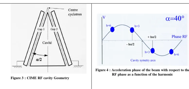
is the azimuthal aperture of the cavity and h the harmonic (Figure 3 and Figure 4).
Figure 3 : CIME RF cavity Geometry
Figure 4 : Acceleration phase of the beam with respect to the RF phase as a function of the harmonic
The isochronism condition, B(r)=
γ
(r)B
inj, has to be fulfilled to accelerate the beam. We
assume that the
γ
(r) variation for energy in the 1 to 2 MeV/A range is not significant
compared to higher energy. We use then the current value of the isochronism coils calculated
for the harmonic 5. Additionally, the harmonic 5 and 6 have a common RF frequency region
for 1,7 MeV/A. The
γ
(r) is the same at this point. It will be our first study energy.
3. Machine study
The machine study was split into 3 from march 2004 to March 2005. It was decided to take
advantage of the operators in order to benefit from their presence the evenings, weekend and
public holidays. This continuity in the machine tuning largely contribute to converge to a
tuning solution. Indeed, one could consider that the maximum in output for a given
adjustment had been reached when the operators acknowledged themselves overcome.
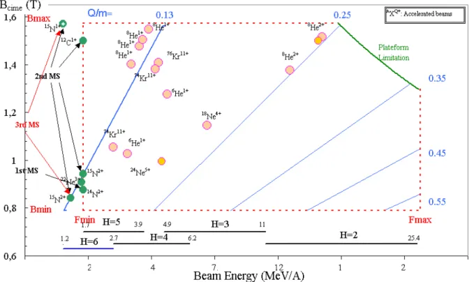
The Figure 5 shows the various tuned beams (green dots) over the three harmonic 6 machine
studies.
Figure 5 : CIME working diagram. In orange dots the SPIRAL accelerated beams. Green dots represent different beams done for the harmonic 6 study machine.
The table below, summarizes the machine parameters for the different tunings.
Beams 12C1+ 12C1+ 15N1+ 15N2+ 15N2+ 15N2+ 15N1+ 15N2+ 15N1+
Harmonic H5 H6 H6 H5 H6 H6 H6 H6 H6
Energy [MeV/A] 1.74 1.74 1.21 1.74 1.74 1.4 1.2 1.4 1.2
Frequency [MHz] 9.6 11.52 9.6 9.6 11.52 10.34 9.6 10.34 9.6
Extraction magnetic rigidity
[T.m] 2.28 2.28 2.376 1.425 1.425 1.278 2.376 1.272 2.376
Magnetic field [T] 19786 19783 20580 12331 12331 11052 20578 11053 20576
Efficiency Output / input
12C1+ at 1.74 MeV/A and H5 and H6
As told in §2, there is an energy, (1,74 MeV/A) common to the harmonic 5 and 6. The RF
frequency is respectively 9.6 MHz and 11.52 MHz (Figure 5).
It is then possible to tune a beam in harmonic 5, with known parameters (25% transport
efficiency, from the analyze point to the CIME ejection line) and flip to the harmonic 6 with
the same beam and magnetic field configuration and by changing simply the phase between
cavity, the frequency and applying the new RF cavity voltage (calculated with LIONS code)
to pass correctly through the RF cavity gaps.
An efficiency of 16% was achieved.
15N1+ at 1.2 MeV/A and H6
The overall transport efficiency is around 15 to 17%. One can expect to gain few percent
with more tuning time. Figure 6 shows the beam turns. There is 86 turns well defined. An
excellent isochronism is reached, Figure 7.
Figure 6 : Beam turn measured in harmonic 6 in CIME
Figure 7 : Isochronism plot measured in CIME in harmonic 6.
15N2+ at 1.4 MeV/A and H6
Transport efficiency from the source to the analyse point decreases due to the space charge
effect in the beam at low platform voltage (below 10 kV). An émittance dilution is induced,
increasing the beam envelopes. The acceptance of the beamline is then not enough to
transport the beam without loss.
CIME radius(mm)
Beam phase/ RF (°)
The efficiency are around 10% but with closed émittance slits. With opened slits, the
transport efficiency in the injection beam line is reduced by a factor 2.
4. Conclusions
The acceleration of an ion beam at low energy with the harmonic 6 is feasible.
The energies studied are the following :
•
1.2 MeV/A with
15N
1+ •1.74 MeV/A with
15N
2+ •1.4 MeV/A with
15N
2+ •1.2 MeV/A with
15N
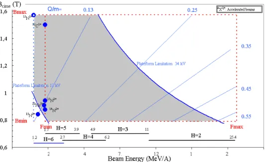
2+The injection inflector is designed to inject the beam at a radius of 45 mm in the cyclotron
CIME. This centre, as shown in Figure 8, allows to stay above the 10 kV source extraction
voltage for charge over mass ratio (Q/m) above 0.1. The space charge effect is contained. For
the harmonic 6, one a part of the working diagram at low CIME field level is below the 10 kV
limit under space charge regime. Experimentally, the space charge effect have been seen
through the important beam loss along the low energy beamline due to the emittance dilution
and consequently large beam envelope. To avoid such a beam losses (factor 2 at least), one
has to :
•
work at high CIME field for 0.06 < Q/m < 0.1 (Figure 8) For example, from the
available spiral beam (in theGANIL website), The
17Ne and heavier beams could
beam accelerated down to 1.21 MeV/A with respect to the Q/m condition. On the
other hand, the following radioactive ions,
6He,
8He,
13N,
14O and
15O can not be
accelerated at 1.21 MeV/A
Or
•
design a new injection centre for CIME to bring the beam at higher energy meaning
higher radius (60 mm) for example. This study should decide to replace or not the
cavity extremities
3
TECHNICAL
DEVELOPMENTS
The CICS Project ( Irradiation Control of the Spiral Target)
P.AngerAbstract : The CICS project aims at optimizing the Spiral facility experiments schedule as well as the
exploitation costs, by controlling the maximum dose (maximum number of ions stopped in the Spiral Target), a new safety criterion.
1. Introduction
The SPIRAL unit generates a radioactive ion beam by irradiating an ECS “Ensemble Cible-Source”
(Target- Ion Source) with a high energy ion beam. GANIL is a facility submitted to approval , and the
irradiation mode of targets is regulated by the safety authorities. At present, the target irradiation is limited by a safety criterion of 15 days of use , independently of the irradiating beam characteristics(ion species, power and risks linked to the operation of the accelerators). A request for modification of this criterion has been formulated to the safety authorities. It does not impair the safety level of SPIRAL. The maximum irradiation time authorised should depend on the irradiating beam type and of its intensity, the new criterion being that the total number of ions received by the target (integrated flux) should not exceed a certain level, function of the radiological risk. The target irradiation time will nevertheless remain linked to the operation schedule of the accelerators (6 to 10 weeksperiods).
In order to control this new criterion, the CICS project (Contrôle de l’Irradiation de la Cible de
SPIRAL) (Irradiation Control of the SPIRAL Target) has beenissued: it will require a measurement system and
a reliable control of the beam intensity which will, at any time, show both the instantaneous and the integrated beam intensity for each target. The intensity means the number of ions per second.
2. Description of the system
The system (fig.1) consists of two sensors measuring the intensity of the primary beam irradiating the ECS (Target- Ion Source) and returning an electric signal proportional to the intensity. A dedicated chain of measurement will handle the signal of each sensor so that they can be digitized by a computing system. This dedicated and autonomous computing system will be able to test the two instrumentations and handle any malfunctions. Using an user interface, this computing system will receive the necessary information from the primary beam, the identification of the ECS and the maximum authorized number of incident ions in order to measure the intensity of the beam, calculate the number of particles per second and integrate the number of ions stopping in the target. The computing system records the data related to the irradiation of each ECS on two reliable and permanent data carriers. It cuts off the beam either when a ma lfunction occurs or when the target has received the maximum dose (new safety criterion). Via an interface, the system will keep users informed of its configuration and of the operating data.
Treatment Computer system
Users Interface Storage
device
Beam•
Type of beam (A, Z, Q, E, F)•
Safety criterion(NB max ions) Identification of
ECS unit
•
Information•
Alarms Users Beam cut-off ECSSS
Test Test Non interceptive beam intensity sensor3. Principle of the measurement of the beam intensity
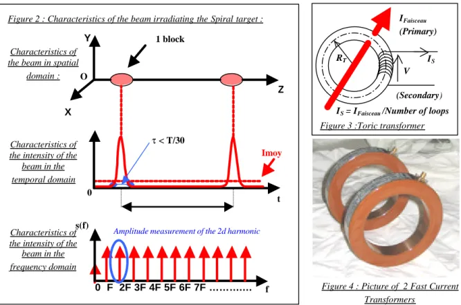
The beam intensity is obtained by measuring the magnetic field generated by the pulsed beam (fig.2) with a Fast Current Transformer.
The current transformer (fig.3) generates an image signal of the beam intensity to a treatment chain ; then, the amplitude of the second harmonic of the signal is detected by a Lock-in Amplifier. The average value of the intensity is calculated through the relation between the 2d harmonic amplitude and the average value in the Fourier expansion :
2
)
4
(
1
)
2
cos(
2
2 2 2 0a
F
F
a
a
≅
−
=
τ
τ
π
ifF
1
<<
τ
This measuring equipment is doubled (fig.4) in order to ensure an active redundancy which guaranteed the validity of the measurement. The measuring equipments are calibrated in order to establish the global accuracy of the measurement and therefore to deliberatly overestimate, by programming, the calculated intensity.
4. Mechanical integration
The sensor (fig.5) is installed in the L4 beam line a few meters before the SPIRAL target (fig.6).
Figure 5 : Mechanical assembly of the sensor the sensor 1 block τ < T/30 Imoy Z Y X 0 t Characteristics of
the beam in spatial domain :
Characteristics of the intensity of the
beam in the temporal domain 0 F 2F 3F 4F 5F 6F 7F ……….… nF f Characteristics of
the intensity of the beam in the frequency domain
Amplitude measurement of the 2d harmonic
O
s(f)
Figure 2 : Characteristics of the beam irradiating the Spiral target :
Figure 4 : Picture of 2 Fast Current Transformers
IS = IFaisceau /Number of loops
RT V (Secondary) IFaisceau (Primary) IS
Figure 3 :Toric transformer
Line 4 High Energy Mechanical Integration
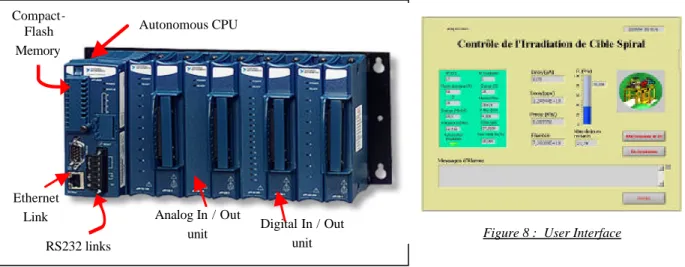
5. Description of the computing system
It is basically composed of a real time industrial controller of the Compact Fieldpoint type (fig.7). It is autonomous, has its own operation system and is programmed under Labview. The system must obtain the detected intensity of the beam, calculate the particle fluency, stop the beam with a beam stopper block if the level is exceeded or in case of malfunction. It will record the irradiation history on a local memory and provide a link to the PC user. The system will also have a user interface in order to configure the system and to keep the users informed (fig.8).
6. Quality Assurance
The study, implementation and operation of this system need to satisfy quality requirements in order to control the new safety criterion. The intensity measurement veracity, the malfunction management and the overall reliability were taken into account from the beginning. For example, the uncertainty of the measurement chain will be treated whatever the beam frequency, the pulse length, the operating temperature of the subsets, and also whichever units or refill installed.
7. Conclusion
This project is nearly completed ; it is awaiting starting-up authorisations for the validation of the concept (control system of the new safety criterion) by the safety authorities. It will greatly improve the production tool that SPIRAL represents. It will allow a better management of target irradiation by lowering the number of ECS
(Target- Ion Source) used every year. This should decrease SPIRAL‘s production costs and provide a better
response to the physicists’ demands for beam scheduling as well as a reduction of the amount of generated waste.
References :
[1] S.Faure , « Limite d’irradiation d’un ECS de SPIRAL », internal document 2003, SPR213B
[2] F.Loyer, « Cahier des charges fonctionnel du projet CICS », internal document 2003, P-CICS-01-A CdCF
[3] P.Anger, « Plan de développement du projet CICS » internal document 2003, P-CICS-002-PDD-A plan de développement
[4] P.Anger and the Project Team : C.Doutressoulles, M.Ozille, JF.Rozé, B.Jacquot, M.Dubois, S.Faure, F.Bucaille, C.Mauger, JC.Deroy, « Cahier des Charges et des Clauses Techniques du projet CICS » internal document 2003, P-CICS-043-CdCCT-A.
Figure 8 : User Interface
Analog In / Out
unit Digital In / Out unit Autonomous CPU Ethernet Link Compact-Flash Memory RS232 links
Improvement of the mass separation power of a cyclotron by
using the vertical selection method
P. Bertrand, F. Daudin, M. Di Giacomo, B. Ducoudret and M. Duval
Abstract
It is well known that cyclotrons are very good mass separators, specially when the number of turns in the machine is large. This property is particularly interesting if the cyclotron unavoidably accelerates multiple species of radioactive beams simultaneously, which is the case for the cyclotron CIME at GANIL. We propose to improve the natural mass separation power by using a vertical resonance effect: it consists of putting two small electrodes between the poles, which provide a vertical electric field operating at two frequencies close to twice the RF frequency and which are tuned with respect to the vertical betatron oscillation. A prototype has been designed and built at GANIL, and tested successfully in the cyclotron CIME during 2004.
INTRODUCTION
In what follows, we will present successively the theory, the particle simulation, the prototype design, the first experiments and recentand future improvements.
THEORY
Let’s consider the vertical motion of a particle (q,m) in a cyclotron, where two electrodes are installed above and below the median plane, between the radii r1
and r2 near the extraction radius and with an angular
extent ∆θ (variable potential V, gap g). Introducing the vertical betatron oscillation parameter ν, the Dirac function δ, the angular pulsation ω, the azimuthal second derivative z”,the RF harmonic h and the phase
∆φ = h∆θ , we can write the equation:
) 2 ( 2 ) ( ) ( ) ( ) 1 ( " 2 2 z hfB f g t V gm t qV t z z π φ θ ω α δ α ν ∆ = ∆ = = +
In order to simplify the equations, let’s consider the case
ν=1/4 and introduce the constant one-turn transfer
matrix T and the variable one-turn vertical “kick” matrices Bi : ) 3 ( 0 ; 0 4 / 1 4 0 = − = i i B T α
A particle with the initial conditions u0=(z0,z’0) will have the following turn-by-turn transformation :
4 3 2 1 0 4 3 4 3 2 1 0 3 2 3 2 1 0 2 1 2 1 0 1 B TB B TB u B Tu u B TB B Tu B Tu u B TB u B Tu u B Tu u + + − − = + = + + − − = + = + + − = + = + =
Due to the particular choice of ν, we see that the particle comes back to the initial conditions after 4 turns, if the vertical kicks are all equal. However, if we choose the successive kicks judiciously with respect to the natural oscillation of the particle, it is possible to make a powerful vertical resonance appear. Let’s choose:
) 4 ( ) 2 sin( ) sin( 2 ϕ π α ϕ νθ α α π θ + = + = = i i i i i
After 4n turns, we obtain:
) 5 ( 4 ) sin( ) cos( 8 0 4 − + = u α n ϕϕ u n
which shows that the vertical amplitude of the particle oscillation increases linearly with the number of turns. If 1/ν is not equal to 4 (or not integer), the
demonstration is more sophisticated but the effect remains the same. Moreover, we can show that this resonance occurs for the particles having different initial conditions. In fact, this linear effect does not affect the emittance of the bunch.
Having in mind that we want to preserve the acceleration of the reference beam (well isochronised), and to deflect the other species (shifted in phase) verticaly, the best would be to multiply the time -dependant potential signal corresponding to (4) by a normalised square wave (stepped or not), denoted by H(t) :
) 6 ( ) ( ) sin( ) ( max t H t h V t Videal = νωhf
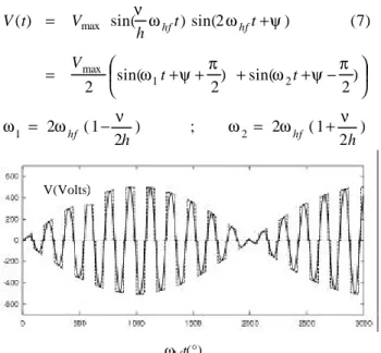
However, it is not technically straightforward to generate such a signal, so that for our prototype, we have replaced it by a sinusoidal one, with a frequency equal to 2fhf, in order to increase the efficiency at 45° instead of 90°, and with a tunable phase ψ (see also figure 1):
) 2 1 ( 2 ; ) 2 1 ( 2 ) 2 sin( ) 2 sin( 2 ) 7 ( ) 2 sin( ) sin( ) ( 2 1 2 1 max max h h t t V t t h V t V hf hf hf hf ν ω ω ν ω ω π ψ ω π ψ ω ψ ω ω ν + = − = + + + + − = + =
Figure 1: Ideal and realistic potential signals V(ωhf). We conclude that two signals with frequencies close to 2fhf and with the same amplitude must be generated on one of the electrodes, which requires a large bandwidth. Considering that the excited species are stopped on two horizontal slits separated by a gap g, we can also deduce an estimation of the potential needed:
) 8 ( 15 . 1 1 2 . 2 max ≈ ∆ = K n h B f g K V hf z θ πν
PARTICLE SIMULATIONS
In order to check the theory, we have simulated the partical behaviour with our code LIONS [1]. We have chosen one of the available measured magnetic maps (Bz=1.5T, ν=0.269) and fhf=11Mhz using the harmonic
h=3. The results are in very good agreement with the
equation (8) , so that we have fixed the objective of the prototype to Vmax=500 V in order to preserve some
margin. (figure 2).
Figure 2: Typical vertical resonance trajectory (top) and applied potential between turns 200-210 (below).
PROTOTYPE DESIGN
Mechanics
The electrodes consist of two copper sheets
(length=250mm, angle=5°, gap=18mm) mounted inside an open-ended aluminum box extended by a cylinder towards the vacuum-chamber flange (figure 3). The upper electrode is connected to the box, which is grounded and protects against exterior perturbations. The electrode below receives the RF signal from a 1.2mm wire, left at a constant distance from the ground box in order to keep the caracteristic impedance fixed
(Zc=240Ω, L=60cm). Two insulated copper plates at the
entrance allow us to measure beam current losses. The whole device is installed in the hill gap of one cyclotron sector.
Figure 3: View of the prototype device with the upper part and electrode lifted off.
Figure 4: View of the prototype device installed into the cyclotron CIME.
Signal generation and power circuits
In order to obtain the desired electric field between the electrodes, we have designed and installed a power circuit as indicated in figure 5: the driving signal is generated in the control room, by mixing the second harmonic of the CIME RF signal (carrier port) and a frequency generator signal tuned at the “?/2h” value (local oscillator port). The center frequency rejection is better then 40 dB and the two needed frequencies have identical levels.ωhft(°)
V(Volts) ))
L≈1µH mixer Zc ≈ 240 Ω L≈0.6m C ≈35 pF inside cyclotron near cyclotron In control room R = 50 Ω 300 Watts x2 phaser fhf ∆f synt h
Figure 5: Power circuit and the electrodes. As a high voltage and a large bandwidth are required, a resonant circuit with a low Q is necessary. Moreover, we need a solution with low losses inside the vacuum chamber, so that cooling is not necessary. The power circuit design is based on the series resonance of a quarter-wave resonant line loaded with the equivalent electrode capacitance (figure 5).
The transmission line is split into two sections in order to avoid some obstacles present in the vacuum chamber, and its length is shortened by a lumped inductance to use the vacuum feedthrough in a very low impedance region, already insensible to the characteristic impedance change.
Outside the vacuum chamber a second inductance is used for fine tuning and a 50 Ω series resistor ensures the Q dumping and the impedance matching to the amplifier. The fine tuning is important to amplify the two signal components equally and to avoid distortion effects.
FIRST BEAM TESTS
We achieved the first beam test with our prototype in september 2004. Due to a lack of available time, it was not possible to tune the machine with 2 simultaneous ion species close one to the other. The accelerated stable beam was 16O5+ with Fhf =11.326Mhz, B0=1.46 , h=2.
The procedure to induce and optimise the vertical resonance effect was very simple an was less than 15 minutes long, the beam having been previously isochronised and extracted. We chose ∆f=1.52Mhz, corresponding to the estimated νz=0.269. Then we
shifted the phase of the signal between –90°and 90° in order for the loss peaks to appear (-45° and +45°), measuring them with the beam current probes. Then we tuned the phase to 45° and reoptimized the ∆f. Once the resonance was obtained, we returned the phase to 0°, and checked that the beam passedcorrectly through the device and through extraction. In order to simulate the presence of another beam, we applied a slight ∆B/B variation and checked that the beam was vertically deflected and stopped by the slits.
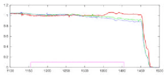
Figures 6 and 7 show that the resonance effect occurs efficiently and that the desired beam is not disturb ed. In fact the main difficulty was to minimize the phase width of the beam itself, and reduce an unexpected precession probably due to rather approximate knowledge of the acceleration parameters (e.g. angle at injection). The direct consequence was that we needed more potential than expected to make the beamvanish vertically (around 500 Volts instead of 300).
Figure 6: Normalised beam current as a function of the radius (isochronised) : red = no voltage, green ≈ 370V,
blue ≈ 500 V, pink=position of electrodes.
Figure 7: Normalised beam current as a function of the radius for a beam phase shift of 40° : red = no voltage,
green ≈ 370V ,blue ≈ 500 V.
Another set of tests were performed in november 2004. The aim was to check that the device works correctly by using the harmonics 4 and 6, in particular at very low energy, and to use our exotic diagnostics at very low current, in order to prove that we can suppress pollutants in the case of a realistic situation (very low beam current).
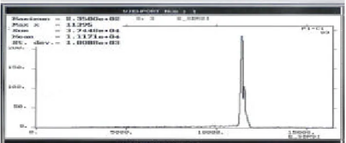
Figures 8: Measurement of Oxygen (majoritary) and Carbon using the Silicium beam diagnostic inside CIME.
Figure 9: Total mass measurement. Using the VMS, the carbon is completely eliminated
As an example, Figures 8 shows Oxygen and Carbon simultaneously accelerated in the machine, and Figure 9 shows how the Carbon pollutant is eliminated using the Vertical Mass Separator (VMS).
RECENT AND FUTURE
IMPROVEMENTS
The tests perfo rmed in 2004 have suggested several improvements:
A capacitive pickup on the electrodes, installed in January 2005, will allow us to tune the resonant circuit, in order to obtain equal peaks on both signals and avoid losses of the beam of interest.
A 25 Ω resistor able to accept 500 watts will give a better circuit gain ( proportional to 1/R) and allow us to use a more powerful amplifier, if necessary. We checked in January 2005 that the signal generated at the
electrodes when using a 25 Ω resistor, was greater in amplitude and not deformed, and that the reflected power was acceptable.
Adjustable vertical slits could be a very power tool : by tuning their gap according to the pollutant masses, we could choose the separation efficency on line, according to the physics requirements.
CONCLUSION
We have proved experimentally that the Vertical Mass Separator concept works without any major difficulty, provided that the beam is tuned correctly.
We are convinced that with the improvements suggested and in the frame of SPIRAL 2, we could reach a mass separation of about 6.10-5 and eliminate a
significant part of the isobaric pollutants.
One question could be: what is the theoretical limit
? In the ideal case of a “round beam” cyclotron, for
which the “natural” mass separation could be 3.10-4 (as in CIME) and the phase extension of the beam could be ±2 degrees (as at PSI), the mass separation would
be
less than 2.10-5 by using adjustable vertical slits. Note that the “round beam” concept can work for low intensity beams (e.g. RIBs) as proved in [2].
acknowledgments
We would like to thank all those who helped us during the device installation and the first beam tests, in particular : F. Chautard, M. Desmons, M. Gallardo, C. Galard, A. Lemarié, M.H. Moscatello and A. Savalle.
REFERENCES
[1] P. Bertrand: “LIONS: a new set of Fortran 90 codes for the SPIRAL project at GANIL”. 4th ICCPO, Japan, (1994).
[2] P.Bertrand, Ch. Ricaud: “Specific cyclotron correlations under space charge effects in the case of a spherical beam”. 16th Internat. Conf. on Cyclotrons and their applications. (2001). [3] P. Bertrand, F. Daudin, M. Di Giacomo, B.
Ducoudret, M. Duval: “Improvement of the mass separation power of a cyclotron by using the vertical selection method”. 17th Internat. Conf. on Cyclotrons and their applications. Tokyo (2004).
Improvements on stable beams from ECRIS
P.Lehérissier, F.Lemagnen, C.Canet, C.Barué, JL.Flambard, M.DupuisL’année 2003 fût marquée par la mise en œuvre de la technique de recyclage par SF6, pour la fourniture d’un faisceau
intense de germanium. La mise au point d’un four haute température (High-Temperature Oven – HTO) destiné à l’augmentation de l’intensité du faisceau d’uranium, s’est poursuivie. Un premier essai en Vanadium a été effectué sur la source d’ions ; Parallèlement la méthode de sputtering a donné un faisceau stable U 31+ de 0.5 eµA. En 2004, la poursuite du développement du HTO a été différée et la priorité mise sur les essais en ligne du four à grande capacité (Large Capacity Oven - LCO). L’objectif est l’augmentation des intensités des faisceaux de Ca, Pb, Sn et Mg. Par ailleurs, la méthode « MIVOC » a été utilisée avec succès pour la production de faisceau de haute intensité à partir du magnésocène (24Mg5+ ~ 110 eµA) et aussi pour des faisceaux de Fer et de Nickel issus de composés organométalliques synthétisés par un laboratoire de l’université de Caen .
In the year 2003 we used for the first time the recycling effect of SF6 for the production of a high intensity beam of
germanium. The development of the High-Temperature Oven (HTO), with the aim of about 10 eµA of U 25+ beam production, was continued. A preliminary test with vanadium was achieved on the ion source. In the mean time the sputtering method was used and g ave a stable beam of U 31+ of 0.5 eµA. In 2004, the development of the HTO was delayed. The main priority was the test on-line of the Large-Capacity Oven (LCO) for the increase of the calcium, lead, tin and magnesium beam intensities. We have also succeeded with the “MIVOC” method for the production of high intensity beam of magnesium (24Mg 5+ ~ 110 eµA), and for iron and nickel beams from “home-made” organometallic compounds synthesised by a laboratory of the University of Caen.
I - Recycling of Germanium with SF6 gas
The recycling effect of germanium with SF6 gas [1] on an
ECRIS, observed in 2001, has been studied, then used as beam for research of superheavy elements at the end of 2003 (76Ge + 208Pb à 283114 + n). A beam of 1 pµA was delivered to the experiment. First, three loads of GeO2 were
evaporated into the source using the micro-oven and with helium as support gas. For 4 days, 150 mg of 76Ge were consumed and the ionisation efficiency for Ge was around 4%. Then a very stable beam of 76Ge 10+ with an average intensity of 35 eµA, was produced for 17 days, using SF6
as support gas (Fig. 1).
0 20 40 60 80 145 190 235
Analysing magnet current (A)
Faraday cup (eµA)
7+ 6+ 5+ 11+ 10+ 9+ O1+ 13+ F2+ F3+ O2+ O3+ 9/11/2003
Figure 1: Germanium spectrum – recycling with SF6 gas.
Fluorine coming from dissociated SF6 gas in the plasma
reacts gradually with thin layers of germanium or germanium oxide deposited on the walls. A germanium tetrafluoride (GeF4) vapour is directly produced in the
plasma chamber and ionised as a gas, leading to a high ionisation efficiency of 38%. The intensity and the request charge state can be adjusted by varying the RF power and the SF6 flow rate. The easy tuning of the source, the
stability, the very small background noise of the beam, the high intensity and the ionization efficiency confirm that the
source behaves as well as with a gas. The main source parameters were: RF power 60 W, high voltage 66 kV/1.3 mA. Previous tests on 76Ge13+ beam gave us 35 eµA with a RF power at 230 W.
II - High-Temperature Oven
A High-Temperature Oven [2] able to reach 1900°C was designed and built for the production of an intense uranium beam (10 to 20 eµA of U25+). This high operating temperature prohibited the use of any ceramic, which is a limitation for the present micro -oven. The HTO has a coaxial geometry (Fig. 2).
Figure 2: HTO components and coaxial tube.
Two external coaxial tantalum cylinders – used as reflectors – and a filament holder, are fitted together into a copper tube which is also the RF coaxial line. The copper tube is welded to a water-cooling flange. The inner part is made of two coaxial tantalum cylinders used as a filament holder and fitted together into a stainless steel tube which allows the introduction of either a movable crucible or gaseous compounds. The tungsten filament (φ 0.5 mm) has a conical shape, giving a better mechanical stability, and
15 mm), made of a refractory material suitable for the required compound, is movable and can be refilled without breaking the vacuum in the source. A temperature of 1800°C has been measured for an electrical power of 310 W (18 V / 17 A),with the off-line prototype. A temperature higher than 1700°C has been maintained for 50 hours. First evaporation tests with vanadium (vapour pressure: 10-2 mbar at 1850°C) into a tantalum crucible were successful (1 mg/h at 200 W for 20 hours). However, the next tests with melted metallic uranium or solid uranium oxide failed. A chemical reaction with the melted uranium destroyed the tantalum crucible.
A on-line version, with a longer copper tube, was built for tests with the ECR 4M source. Despite increasing the DC heating current up to 18 A, we do not observe any constraints on the filament located near the maximum magnetic field of the source.
First tests with lead at low temperatures gave the same performance as those obtained with the standard micro -oven and validated the increase of the diameter of the coaxial tube up to 18 mm. However, tests with vanadium at high temperature failed. Copper peaks appeared in the spectrum. The appearance of the copper tube close to the tantalum reflectors was observed to have changed. Thermal simulations, without RF power, showed that this part of the copper tube could reach up to 840°C. This could explain the difficulties encountered with the tuning of the vanadium beam. Modifications have to be made to increase the cooling of the copper tube. Although the mechanical concept of the heating part has been successfully tested, some improvements are necessary to adapt the oven to the ion source.
III - Uranium beam by sputtering method
The sputtering method has been tested for the production of a uranium beam with a high charge state, i.e. U31+ [2] . Previous runs using neon as support gas for producing U25+ and U28+ gave intensities of 2 eµA and 0.8 eµA respectively, but with a high consumption rate, around 7 mg/h. This time the ECR 4M source was tuned for U31+ with oxygen as support gas, and could deliver a beam up to 0.5 eµA. The uranium sample (φ 5 mm, length 8 mm) was fixed via a copper support at the end of a cooling stainless steel tube. An alumina tube insulated it and centred it in the coaxial tube (Fig. 3).
Figure 3: Uranium sample after sputtering with O2. A low consumption rate of 0.33 mg/h was measured. However, the ionization efficiency still remained at a low value of about 1%. The main parameters of the source were an RF power of 210 W, an extracted current of 1.1 mA at 16 kV, and 1 kV / 0.76 mA as sputtering values.
Some short tests were done with SF6 as support gas instead
of O2. The charge state distribution in the spectrum (Fig. 4)
then shifted from U28+ (800 enA) to U24+ (3.5 eµA) but with only 150 W of RF power, and 150 V / 0.5 mA for sputtering parameters. Possibly a process other than sputtering occurred. It could be the formation of UF6 gas
by chemical reaction between uranium and dissociated fluorine. However this effect was not enough to indicate any clear improvement in the uranium intensity.
0 1 2 3 4 5 115 125 135 145
Analysing magnet current (A)
Faraday cup (eµA)
19+ 24+ 23+ 20+ 21+ S3+ 18 µA 27+ 26+ F2+ 90 µA 8/07/2003
Figure 4: Uranium spectrum optimised on U24+, sputtering with SF6
IV - Large Capacity Oven
A Large Capacity Oven [2] has been developed in order to replace the micro-oven used at GANIL since 1985. The same concept is applied with an external diameter of 10 mm (Fig. 5) instead of 5 mm.
Figure 5: Large-capacity oven.
The bigger capacity allows a longer lifetime, particularly with low-density materials, easier filling of the alumina container, the possibility of safe working with molten materials, owing to a movable cap over the opening. The reliability is also increased, with bigger dimensions of all components. The sample or the tantalum container, when running with enriched metallic 48Ca, is introduced inside an alumina container. The coaxial tube diameter has been increased up to 12 mm, with a minor decrease in the gaseous performance. Characteristics are given in table 1.