Design and Prototype -A Manufacturing System for the Soft Lithography Technique By
Arthur Y. Cao
B.Eng., Electrical Engineering National University of Singapore, 2005
Submitted to the Department of Mechanical Engineering in Partial Fulfillment of the Requirements for the Degree of
Master of Engineering in Manufacturing at the
A • oc, l Titto+e+4 f Ta,. .ml
cassa use s ns u e o ec no ogy
August 2006
C Massachusetts
Institute of Technolo
MAssAcHUSETSM INSTITUTE
OFTECHNOLOGY
LIBRARN
2 3 200ES
SLIBRARIES
',LVLLV O AIJJ t 1Of,.LI..LI WC JU•. .L JJLL1.JAJd ••
-All Rights Reserved
Signature of Author
...
...Department of Mechanical Engineering August 18, 2006
Certified by... ... ...
David E. Hardt Professor of Mechanical Engineering
Thesis Supervisor
A ccepted by ... / ... ... ...
Lallit Anand Chairman, Department Committee on Graduate Students
Design and Implementation of a Micro Contact Printing Machine
By Arthur Y. Cao
Submitted to the Department of Mechanical Engineering on Aug 18, 2006 in Partial Fulfillment of the Requirements for the Degree of
Master of Engineering in Manufacturing
ABSTRACT
Ever since 1998 when the term "soft lithography" was first created, soft lithography techniques have drawn close attention of the academia and the industry. Micro contact printing is by far the most widely used soft lithography technique in the industry. The objective of this research project is to design and prototype a micro contact printing machine which could achieve high scalability, feature resolution and production rate. It should also fulfill quality requirements, in terms of minimizing the tool deformation and air trapping furing printing. A reel-to-reel design with wipers to create linear propagation during stamping was used in the final design. The final prototype was made of three stations, the printing station, the inking station and the rotary system, which switches the stamps between printing and inking station. The other important design novelty is that the PDMS stamp has been fixed and the Au coated PET was actually applied to the stamp to get printed. The design minimizes the deformation on the stamp and also eases the linear propagation of the printing interface. The reel-to-reel design can be easily scaled up for mass production with large volume. The prototype was tested and the printing samples were made.
Thesis supervisor: David E. Hardt
ACKNOWLEDGEMENTS
There is an old saying in China which says that whenever you drink some water, think about the source of it. Now, I'm drinking the "water", which is the completion of the Master study in such a great institution like MIT, I have to think about all the sources.
I would like to thank my parents. They provided all the supports that possible, physically,
mentally, spiritually. Being part of a great institution like MIT was only a dream of the greatest kind but they helped me make it into a reality. Thank you, dad and mum.
I would like to thank Professor David E. Hardt for his guidance, patience, support and generosity in imparting his valuable knowledge over the course of my graduate degree. Whenever there was any academic problem, or even other problems, he was there ready to provide help more than you need. He is a true gentleman. I am indeed honored to have worked under his mentorship. Thank you, for being a great guru and a flawless gentleman invoking my most sincere awe.
My gratitude has to go to Xiao Ni for her unselfish and complete support throughout the
whole year. Without it, I could hardly imagine where I could end right now.
Thank Hyung-Jun, from whom I have learned so much, for his kind and encouragement help all the time.
Thank everyone in MIT LMP lab, Grant, Kunal, Munhee, Sam especially. You guys make me feel like home.
Finally, my Lord, once again you have shown your mercy and love on me. Thank you, Father.
TABLE OF CONTENTS
1 Soft Lithography ... 1
1.1 An Introduction to Soft Lithography 1
1.2 The Soft Lithography Taxonomy 2
1.3 Overview of the thesis 8
2 Replica M olding... 10
2.1 Introduction to replica molding 10
2.2 Micro contact Printing Procedure 12
2.3 Previous works related to gtCP automation 17
3 Microcontact Printing ... 21
3.1 Introduction. 21
3.2 Principle and Characteristics. 21
3.3 Micro contact printing procedures. 24
3.4 Critical factors for micro contact printing 26
3.5 Summary of manufacturing considerations. 34
3.6 Industry design effort for micro contact printing 37
3.7 Conclusions. 39
4 Concept Development & Evaluation ... 40
4.1 Introduction 40
4.2 Contact Initiation & Propagation 41
4.3 Automation concept for manufacturing process 47
4.5 Alternative Concept Design 63
5 Design and Implementation of the Inking Station ... Error! Bookmark not defined.
5.1 Design overview 64
5.2 Concept analysis for the inking station 71
5.3 Component design and analysis Error! Bookmark not defined.
5.4 Machining and Material 98
6 Design Novelties, Future Development and Alternative Design... 101
6.1 Design Novelties 101
6.2 Potential problems and future improvement 103
6.3 Alternative designs for the inking station 112
7 Conclusion and Future Work ... 116
7.1 Conclusion 116
7.2 Future work 117
A ppendix ... ... 118 R eference ... 134
LIST OF FIGURES
Figure 1-1-1 Schematic illustration of the procedure for fabricating PDMS stamps from a
master having relief structures on its surface ... 11
Figure 1-2 Schematic procedures for pCP of hexadecanethiol (HDT) on the surface of gold: printing on a planar surface with a planar stamp ... .... 12
Figure 1-3 Schematic illustration of procedure for replica molding (REM) ... 13
Figure 1-4 Schematic illustration of procedure for micro molding in capillaries (MIMIC) 14 Figure 1-5 Schematic illustration of procedure for micro transfer molding (pTM) ... 14
Figure 1-6 Schematic illustration of procedure for solvent-assisted micromolding (SAMIM) ... 15
Figure 2-1 Types of material filling errors...19
Figure 2-2 Types of scrape removing methods... .... 21
Figure 2-3 Types of substrate placement methods ... 22
Figure 2-4 Illustration of Heating Transfer Processes ... 23
Figure 2-5 several types of PDMS stamp deformations ... ... 27
Figure 3-1: Schematic illustration depicting the application of a PDMS stamp containing thiols to a polycrystalline metal film... ... ... 30
Figure 3-2. Self assembled monolayers. ... 31
Figure 3-3: Micro contact printing procedure ... 32
Figure 3-4: Relationship between thicknesses printed with 0.2 milli Mole solution of ECT ink ... ... ... ... 35
Figure 3-5: Relationship between printing time and the number of defects in the pattern ..35
Figure 3-6: Quality of Micro contact printed gold structures performed in the case of an ECT contact-inked stamp ... 36
Figure 3-7: Illustrations of (a) basic geometry of a PDMS stamp and stamps deformed into contact with substrates under (b) required minimum and (c) excess pressures ... 37
Figure 3-8: Three different types of inking for Micro contact printing...39
Figure 3-9: Three contact propagation methods...40
Figure 3-10: Schematic illustration of possible deformations of microstructures in the surfaces of elastom ers. ... ... 43
Figure 3-11: Schematic procedure for conducting pCP with a rolling PDMS stamp ... 44
Figure 4-1: The basic concept of polygonal inking ... 51
Figure 4-2: The finalized inking design. ... 52
Figure 4-3: Roll Stam ping... ... 55
Figure 4-4: Elastic strain induced in the stamp with Roll Stamping. The strain is...56
Figure 4-5: The basic concept of polygonal stamping ... .... 57
Figure 4-6: The stamping tool proposed for Polygonal Stamping ... 58
Figure 4-7: The hinge effect of the polygonal stamping tool... 58
Figure 4-8: An illustration of the steps in Pseudo Roll Stamping ... 63
Figure 4-9: Two foam covered cylindrical wipers apply the gold coated PEN sheet onto the PD M S stam p... 64
Figure 4-10: A step by step illustration of the stamping design developed ... 67
Figure 4-11: A schematic illustration of a process centric manufacturing system showing the integration between the inking-stamping steps and etching ... 68
Figure 4-12: Another version of the manufacturing system discussed before ... 69
Figure 5-1 Side view of the printing station design... ... 73
Figure 5-2 Solid Model for the Full Machine Assembly ... ... 74
Figure 5-3 the Printing Station ... 76
Figure 5-4 The Printing Station... ... 80
Figure 5-5 The inking procedures ... Error! Bookmark not defined. Figure 5-6 The inking roller with its support frame ... 83
Figure 5-7 Solid Model for the lead screw actuator ... 84
Figure 5-8 Inking lead screw specifications... 85
Figure 5-9 The specifications for the u-channel...86
Figure 5-10 The solid model for the inking roller and arm... .... 87
Figure 5-11 the inking rails ... ... 88
Figure 5-12 The design of the roller arm ... 89
Figure 5-13 The design of the arm connector ... 90
Figure 5-14 the solid model for the rotary table and arms ... 91
Figure 5-15 the layout and specifications of the rotary table... ... 93
Figure 5-16 The specification of the rotary arms ... 94
Figure 5-17 The stamp retainer assembly ... ... 96
Figure 5-18 The design of the top plate ... ... 96
Figure 5-19 The design of the retainer wing ... 97
Figure 5-20 The design of the retainer back plate ... 98
Figure 5-21 Z-motor lead screw specifications... ... 99
Figure 5-22 Z-machine supporting arm ... 100
Figure 5-23 The dimensions of the back plate ... 100
Figure 5-24. The printing stage assembly ... 101
Figure 5-25. The match up of the guiding pins and the retainer ... 103
Figure 5-26. The Guiding Pins Components... 103
Figure 5-27 The top view of the printing stage... 104
Figure 5-28. The design of the rotary table and Z-machine supporting frame ... 105
Figure 6-1. The rigid coupling ... 114
Figure 6-3. Helical beam flexible couplings ... ... 116
Figure 6-4. The possible misalignments between the retainer and the inking rails... 117
Figure 6-5. The sunk rail problem ... 118
Figure 6-6. The bad parallelism problem ... 18
Figure 6-7. The layout of the double acting air cylinder ... 119
Figure 6-8. The push and pull function of the air cylinder ... 120
Figure 6-9 the working mechanism of the 4-way two position cylinder controller ... 120
Figure 6-10. The current vertical positioning system...121
CHAPTER
'
Soft Lithography
1.1. An Introduction to Soft Lithography
Soft Lithography comprises a set of techniques that uses soft materials to enable replication and pattern transfer on a wide range of dimensional scales, ranging from
nanometers to centimeters. These techniques follow a non-photolithographic strategy for pattern transfer based on self-assembly' of molecular layers and replica molding for
carrying out micro and nanofabrication.
Most Soft Lithography techniques have been recently developed and have attracted
significant attention from both academia and industry because of their tremendous potential
to support or even replace conventional means of micro manufacturing. The low capital costs and potential for high volume manufacturing with a variety of materials are significant attractions as well. The control over surface chemistry, required for some
SSelf-assembly is the spontaneous aggregation and organization of subunits (molecules or meso-scale objects) into a stable, well defined structure via non covalent interactions. The information that guides the
assembly is coded in the properties (e.g. topologies, shapes, and surface functionalities) of the subunits; the individual subunits will reach the final structure simply by equilibrating to the lowest energy form. Because the final self assembled structures are close to or at thermodynamic equilibrium, they tend to form
applications in medicine, is possible if using soft lithography. Other potential applications of soft lithography in the near future could include simple optical devices such as polarizers,
filters, wire grids, and surface acoustic wave (SAW) devices (Zhao et al. 1996). Longer term goals include working toward optical data storage systems, flat panel displays, and
quantum devices
1.2. The Soft Lithography Taxonomy
Several different techniques are known collectively as soft lithography. Holistically, every soft lithography technique formally consists of three steps:
(1) Fabrication of a topographically patterned master, for example on a silicon wafer, using a conventional process like photolithography.
(2) Molding this master with a functional organic material (usually Polydimethyl siloxane or PDMS) to generate a patterned template.
(3) Generating a replica of the original template in a functional material or a 1:1 projection of the pattern on a surface by applying the stamp.
I
Fabrication and silanizaton of master,. '. ,, ., , , ,, ' , phooresists or wax
Pouring of PDMS over master PDMS
Curing, and releasang of PDMS
-C I -, -• 1 - -Deormation of PDMS
Painng Sagging
,, -- '- . .
06•>d; . ' " (d<<h).h '
Figure 1-1-1 Schematic illustration of the procedure for fabricating PDMS stamps from a master having relief structures on its surface[2]
The techniques which are collectively known as Soft Lithography techniques are:
(A) Near Field Optical Lithography
A transparent PDMS mask with relief on its surface is placed in conformal contact with a layer of photo resist. Light, from a source, passing through the stamp is modulated in the near-field. If the relief on the surface of the stamp shifts the phase of light by an odd multiple of n, a null in the intensity is produced. Features with dimensions between 40 and 100 nm are produced in photo resist at each phase edge
(B) Micro-contact Printing(yCP)
A thin layer composed of an alkanethiol and ethanol, called "ink" is spread on a patterned PDMS stamp. The stamp is then brought into conformal contact with the
substrate, which can range from coinage metals to oxide layers. The thiol ink is transferred to the substrate where it forms a self-assembled monolayer, or SAM2, that can act as a resist against etching. Features on the substrate are revealed after etch treatment. Features as small as 300 nm have been made in this way[2]. This process
will be discussed in detail in Chapter 2.
I PDL
l,~A~ro
fix
1~?H*~.
Figure 1-2 Schematic procedures for uCP of hexadecanethiol (HDT) on the surface of gold: printing on a planar surface with a planar stamp [2]
(C) Replica Molding
A PDMS stamp is cast against a conventionally patterned master. Polyurethane (typically) is then molded against the secondary PDMS master. In this way, multiple copies can be made without damaging the original master. Xia et al. [3]demonstrated replica molding against elastromeric PDMS molds with resolution <10 nm.
--50 nm
LliŽJ
WCue. p" off
Figure 1-3 Schematic illustration of procedure for replica molding (REM) [41
(D) Micromolding in Capillaries (MIMIC).
Continuous channels are formed when a PDMS stamp is brought into conformal contact with a solid substrate.[5] Capillary action fills the channels with a polymer precursor. The polymer is cured and the stamp is removed. MIMIC is able to generate features down to 1 jpm in size.
Figure 1-4 Schematic illustration of procedure for micro molding in capillaries
(MIMIC) [4]
(E) Microtransfer Molding (4 TM)
A PDMS stamp is filled with a prepolymer or ceramic precursor and placed on a
substrate. The material is cured and the stamp is removed. The technique generates features as small as 250 nm and is able to generate multilayer systems [6]
prpolymer
SRemove excess
propolymer
Place on fe support
Cure, remove mold
dual ilmn
Figure 1-5 Schematic illustration of procedure for micro transfer molding (pTM) [4]
(F) Solvent-assisted Microcontact Molding (SAMIM).
SAMIM (Figure 1-6) forms relief features by spreading a small amount of solvent on a surface of a substrate such that the solvent can dissolve a thin layer of the substrate without affecting the PDMS mold. [7] After dissolving or swelling of a layer of the substrate by the solvent, the resulting fluid or gel is molded against the relief structures
in the mold. SAMIM is similar to embossing in terms of operational principle, but it is different in that SAMIM uses a solvent instead of heat to soften a thin layer of substrate. Moreover, an elastomeric PDMS mold rather than a rigid master is used to imprint patterns on the surface of substrates. [4]
- PDMS mote wemding
Itautd Pl~Mactemoldon a suppor
fOn1
Figure 1-6 Schematic illustration of procedure for solvent-assisted micromolding
(SAMIM) [4] 1.3. Overview of the thesis
This thesis is based on a 10-week internship in a high-tech startup specialized in soft-lithography techniques. The objective of this project is to design and prototype a printing and inking system to simulate micro contact printing. It is highly desired that the design be implemented into the mass production at large scale. This project is a group project with three members, namely Hyung-Jun Kim, Karan Chauhan and myself. Hyung-Jun focused on the design and implementation of the printing station. Karan's part has great focus on
the system automation. And I took charge of the inking station and rotary table/Z-machine system.
The first chapter of thesis is the introduction to the soft-lithography technology, firstly developed in George Whitesides' group at Harvard. [4]. Chapter 2 is a literature review on the replica molding. The manufacturing considerations are covered in Chapter 3. In this chapter, several critical factors, which is also important design metrics, like the inking time, printing time, ink concentration etc, are discussed. Chapter 4 lists several concepts proposed before finalizing on the reel-to-reel design. It also discusses mass production considerations and scalability of the finalized design. It alsoproposes some alternative designs . Chapter 1,2 and 4 are shared among the team, Hyung-Jun Kim,. Karan Chauhan and myself. Chapter 5 elaborates in details the design and implementation of the inking station. In chapter 6, the design novelties, future improvement and alternative designs have been discussed. Chapter 7 summarized the whole thesis.
CHAPTER
2
Replica Molding
2.1 Introduction to Replica Molding
Replica molding duplicates the information for example, the shape, the morphology, and the structure, present in a master. It is a procedure that accommodates a wider range of materials than does photolithography. It also allows duplication of three-dimensional topologies in a single step. It has been used for the mass production of surface relief structures such as diffraction gratings holograms, compact disks (CDs) and micro tools. Replica molding with an appropriate material (usually in the form of a polymer precursor) enables highly complex structures in the master to be faithfully duplicated into multiple copies with nanometer resolution in a reliable, simple, and inexpensive way. The fidelity of replica molding is determined by van der Waals interactions, wetting, and kinetic factors such as filling of the mold. These physical interactions should allow more accurate replication of features that are smaller than 100 nm than does photolithography, which is limited by optical diffraction.[4]
PDMS is most widely used as a master with patterned relief on the surface to generate patterns and structures with feature size ranging form 30 nm to 100 jim. PDMS carries the
following advantages over other materials as the printing stamps: * Surface with good chemical stability
* Gas diffuses easily * Good thermal stability * Optically transparent * Durable
* Interfacial properties easily modifiable
In the replica molding process, the features of the Polydimethylsiloxane (PDMS) stamp can be transferred to many thermosetting polymers, such as Polyurethane (PU), Polyethylene terephthalate (PET), Polyethylene naphthalate (PEN) etc. In this research project, PET/PEN will be used.
The replica molding process can be divided into five main steps. The work piece is firstly applied to the PDMS stamps before the excess material is wiped off. Then the stamp is either placed onto the substrate or goes through the curing process directly. The work piece is then peeled off from the stamp , as the final step. We will explore the manufacturing tactics for each step in greater detail.
2.2
Break down of molding steps
2.2.1 Stepl: work piece material filling
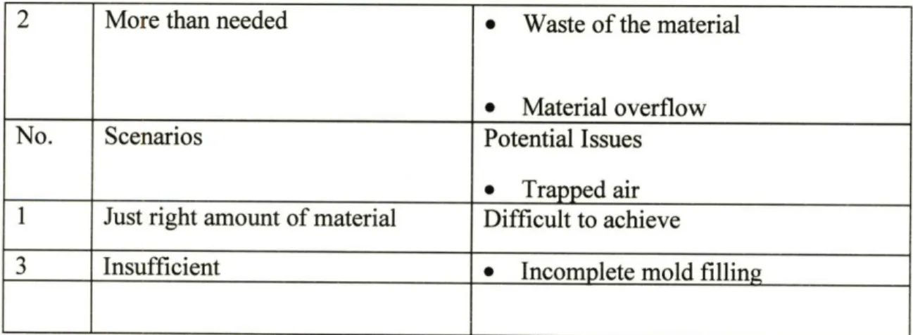
In the filling process, it will be difficult to have exactly the right amount of pre-polymer in the PDMS stamps. Excess material may potentially cause the air-trapping in the work piece in the later stage when the stamp is placed on the substrate while material insufficiency will lead to incomplete mold filling as well as non-planar surface. Figure 2-1 shows the different types of material filling errors graphically and Table 2.1 lists the potential issues with each type.
Scenario
I
Figure 2-1 Types of material filling errors
Table 2.1 Material Filling Scenarios and Potential Issues
More than needed
Scenarios
Just right amount of material Insufficient
* Waste of the material * Material overflow Potential Issues * Trapped air Difficult to achieve
* Incomplete mold filling
2
No.
1
During the filling process, issues like the non-planar surface of the material will also occur. The different scenarios and their associated issues can be found from Table 2.1.
2.2.2 Step 2: Wipe-off extra material
There are two possible ways to wipe off the excess of materials. A Nitrogen stream can be used to blow off the extra material. It is fast, clean and generates a planar surface. The only disadvantage is that excess material recycling is difficult using this method. The alternative method is to use a PDMS plate to wipe off away the extra material .The shortcoming of this method is the lower rate. Also, there is danger that during the wipe-off process, the surfaces of the tool might be roughened or damaged. It could potentially cause the non-planar surface for the work piece as well. Figure 2.2 shows the two excess wiping methods with the nitrogen wiping method 1 and PDMS plate sliding method 2.
2
ri
3 Insufficient * Incomplete mold filling
* Unexpected surface shape 4 Non-planar surface/ Non-uniform * Unexpected surface shape
distribution
* Trapped air
Figure 2-2 Types of scrape removing methods 2.2.3 Step 3: Substrate placement
There are three ways of placing the substrate.
Method 1: Place the substrate directly down onto the work piece. It will cause waste of material and also air trapping
Method 2: Fix one end and bring down the other end down slowly with a constant angle. Method 3: Slide the substrate in at the surface of the mold. The deformation of the mold and non-planar surface of the work piece might be the possible issues with this method. Figure 2.3 shows the three placement methods.
1 2
r4-Figure 2-3 Types of substrate placement methods
The work piece in all the three above methods has been fixed and the substrate is moved. As the alternative to all the three methods, the substrate could be fixed. The prepolymer material is then uniformly distributed on the substrate surface. After it, the PDMS mold is placed onto the substrate. In this way, the mold is placed on the fixed substrate.
2.2.4 Step 4 Curing Process
The material used in this process is called the thermosetting polymers or thermosets. During polymerization, the network of the thermosets is completed and the shape of the part is permanently set. The curing reaction is irreversible.
The polymerization process for thermosets generally takes place in two stages. The first occurs at the chemical plant, where the molecules are partially polymerized into linear chains. The second stage occurs at the parts-producing plant, where cross-linking is completed under heat and pressure during molding and shaping of the part.
The advantage of the material and also the process is normally the better mechanical, thermal and chemical properties, electrical resistance, and dimensional stability than what ? thermoplastics?].
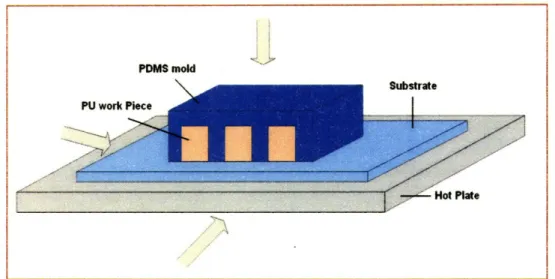
There are two methods of curing using either heat UV radiation. In this research, heat curing was more deeply explored. The heat transfer process includes both convection and conduction, but convection was be neglected in this case. Conduction takes place among a
hot plate, the substrate, the PDMS mold and thework piece. The Figure 2.4 shows the heat transfer process.
Figure 2-4 Illustration of Heating Transfer Processes
There are several design considerations for the heating curing process:
* Heat up the oven at the fastest possible rate to get optimal production rate
* Increase the oven temperature gradually and evenly to avoid the non-uniform heating
* Avoid overheating, as the polymers may bum up or downgrade
In order to achieve faster curing and better quality, the oven should be kept at a constant temperature to avoid repeated heating and cooling cycle.
PDMS mold
2.2.5 Step 5 De-molding processes
As the final step, the de-molding process can also be the most critical. There are many factors associated with the de-molding rate and difficulty.
* Aspect ratio. Aspect ratio is defined as distance between two features divided by the feature height. It will greatly decide the difficulty to peel off the mold. The greater the aspect ratio the harder it is to peel off the work piece and the easier to damage the work piece.
* Mold/Work Piece Channel complexity. The more complex the structure of the mold/work piece, the more difficult it is to peel off is and the more likely defects would be caused in the process.
Other factors, like the heat conductivity of the work piece and the heating/cooling system can also affect the quality and rate of the de-molding process.
2.3 Manufacturing issues for Replica Molding
Key manufacturing issues include the rate, quality, cost, flexibility and the scalability of a process.
The production rate is the major concern for the manufacturing using replica molding technique. There are many factors that can affect the molding rate, among which gel time and de-molding time, which is the materials intrinsic properties, is the most critical and decisive.
Other factors including the material filling rate, process flow rate and the number of molds and productions line.
The material filling rate is decided by the prepolymer viscosity. Pre-heating treatment can dramatically reduce the material viscosity, which leads to the reduction of filling time. The design of the manufacturing system itself will decide the process flow time and the scale of production lines
2.3.2 Quality
Quality is another major concern. The defects or low quality of the final products can be due to various causes, namely
* Deformation of the tools * Trapped air in the product
* Mold not fully filled with Polyurethane
* Deformation to both tool and products during de-molding
The elastomeric character of PDMS is the origin of some of the most serious technical problems.
First, gravity, adhesion and capillary forces exert stress on the elastomeric features and cause them to deform and generate defects in the pattern that is formed. If the aspect ratio of the relief features is too large, the PDMS microstructures fall under their own weight or collapse owing to the forces typical of inking or printing of the stamp. It has been shown that aspect ratios of the relief structures on PDMS surfaces had to be between about 0.2 and 2 in order to obtain defect-free stamps. [4]
Second, when the aspect ratios are too low, the relief structures are not able to withstand the compressive forces typical of printing and the adhesion between the stamp and the substrate; these interactions result in sagging. This deformation excludes soft lithography for use with patterns in which features are widely separated, unless nonfunctional apostso
can be introduced into the designs to support the non-contact regions.
Third, achieving accurate registration without distorting the multilayer fabrication process is substantially more difficult with a flexible elastomer than with a rigid material.
There are several other disadvantages that may limit the performance of PDMS for certain types of applications. For example, PDMS shrinks by a factor of about 1% upon curing, and PDMS can be readily swelled by non-polar solvents such as toluene and hexane.
The elastomeric character of PDMS is also the origin of some of the most serious technical problems. The PDMS stamps can have the paring, sagging and shrinking problems as Figure 2.5 shows.
PDMS r*.,--.-..- Pi~n ·
IJIJ~rml
VrU
-i L)M$ ; I I ) 4Y *0 PI)MS _ N-JoLJ-". ... i I.Paring
Sagging
PDMSShrinking
Figure 2-5 several types of PDMS stamp deformations [4]
PD[ tr
-CHAPTER
3
Micro-contact Printing
3.1 Introduction
Micro contact Printing (or yCP), as it will be frequently referred to in this text) uses the relief patterns on a PDMS stamp to form patterns of self-assembled monolayers (SAMs) of inks on the surface of a substrate through conformal contact. Micro contact printing differs from other printing methods, like inkjet printing or 3-D printing, in the use of self-assembly (especially, the use of SAMs) to form micro patterns and microstructures of various materials .[8]
This chapter provides a literature review of the process including its principles and characteristic features. We also discuss some industrial design efforts to take this technology from the laboratory to commercial production.
3.2 Principles and characteristics of Micro contact Printing
Micro contact printing is a method for patterning Self-Assembled Monolayers (SAMs) on surfaces using elastomeric stamp [9]. The most distinct characteristic of pCP is its use of self-assembly (especially, the use of SAMs) to form micro patterns on a substrate. [10] SAMs are formed by contact between a topographically patterned elastomeric stamp,
wetted with an ink consisting of molecules that are capable of forming SAMs, and the surface of substrate.
Micron scale SAMs by Micro contact printing can be formed manually in a conventional chemical laboratory and it does not require any photolithographic equipment or a clean room environment. Therefore, the simplicity and economic efficiency for patterning micron scale layer are major benefits of Micro contact printing.
Another Characteristic of MCP is conformability. Because the Micro contact printing uses PDMS stamps, the stamp is able to conform to substrate with little external normal force and at the same time can compensate for the surface roughness of the substrate. This is
important in transporting molecular level SAMs.
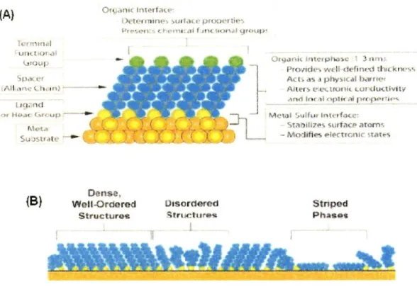
Self-Assembled Monolayers (SAMs) are layers formed on a solid surface by spontaneous organization of molecules. It has been reported that a polymer inked with an alkanethiol and brought into contact with a gold-coated surface can form a monolayer of these molecules in the areas of contact [12].
PDMS Tranoportl-C ;u~ce r ?irruricnre ~c~ - -~-x Metallic Grains, of subotrate 0 nm
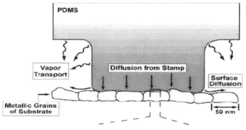
Figure 3-1: Schematic illustration depicting the application of a PDMS stamp containing thiols to a polycrystalline metal film. The mechanisms of mass transport
from the stamp to the substrate are also shown [13].
The ink used in Micro contact printing to form the SAMs is mainly transported through
diffusion at the stamp-substrate interface. Diffusion from the edges of the stamp and vapor transport are the non-contact mechanisms that can also form SAMs (see figure 3.1). When the target feature sizes are smaller than 500 nm, these non-contact transport mechanisms become significant enough to degrade the output quality [14].
The substrates, on which the SAMs are formed, are generally prepared by common physical vapor deposition (PVD) methods, i.e., thermal or electron beam evaporation. Among a wide range of materials used for substrates, gold is the most commonly used as it is easily available as a thin film and easy to pattern by a combination of lithographic tools (photolithography, micromachining) and chemical etchants. In addition, gold is a very inert material, so it does not oxidize at temperatures below its melting point. However, silver
[15] and copper [16] have been used as a substrate for forming SAMs through Micro
)Vjt(ýti4 nn01 .im Id( c po uovr tie.? -·---~ ,44*54 C *Crr fldrt(r~a i, I -44) *4 Q4 * 44
(B)
f'nii-;,d4' wteII (k'f454th d44(krwls-'Ar ,a( 11 (4i p d••i ol t r w4d-'.I
Vlc~v kc- I frai cr ý ulik l
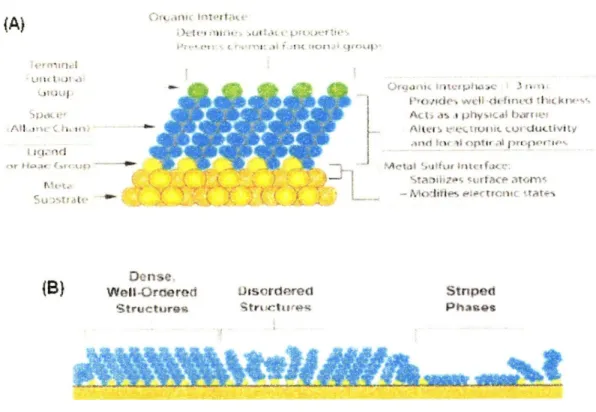
Wtorl Sufcif lntvrfuxýs Srtarili7es surfacP atorn• - Mo-1ifie ieptl;trCJr · taf-s
Dense, Well-Ordered Structur.es Ossorderecd Struitctron Stnped Phases
Figure 3-2. Self assembled monolayers. (A) Schematic diagram of an ideal, single-crystalline SAM of alkanethiolates supported on a gold surfaces (B) The variety of structural arrangements found in SAMs prepared by FpCP when the stamp is wetted
with a 1-10 mM solution and applied to the substrate for 1-10 seconds [17].
3.3
Micro contact printing Procedure.
Micro contact Printing can be thought of as a two stage process: Inking and Stamping.
Inking consists of wetting with the ink and drying. Ink that forms SAMs is transferred
through a solvent such as ethanol, so the solvent needs to be removed after transferring ink
to stamp. The wetting step is applying ink solution to a PDMS stamp and the drying step is
removing solvent from the PDMS. The solvent can be dried in the air, but a stream of nitrogen gas helps to reduce time for drying. Inking and drying times depend on factors
such as ink concentration, printing area, and printing method. Typically, the inking step takes 30 - 60 seconds and drying requires 10 - 60 seconds.
The stamping process comprises 3 sub-steps: Initial contact & propagation, full contact, and separation. Achieving full contact through gradual application of the stamp is important in order to minimize air trapping between stamp and substrate. After achieving full contact, contact time is required to transport inks from a stamp to a substrate and form SAMs. The required length of contact time can be different mainly according to ink type, concentration of ink or target thickness of SAMs.
: kanel·ush *l
==m~
Awl 4'~~SAM
a~lbo, 1
T~t,,,,,r- -muLD~ __ I"
Figure 3-3: Micro contact printing procedure [2].
1--" --- '
Table 3.3 summarizes the process, the required time and typical failure modes of Micro contact printing reported through the research so far.
Table 3.3: Micro contact Printing Process and characteristics
During the filling process, issues like the non-planar surface of the material will also occur. The different scenarios and their associated issues can be found from Table 2.1.
2.2.2 Step 2: Wipe-off extra material
There are two possible ways to wipe off the excess of materials. A Nitrogen stream can be used to blow off the extra material. It is fast, clean and generates a planar surface. The only disadvantage is that excess material recycling is difficult using this method. The alternative method is to use a PDMS plate to wipe off away the extra material .The shortcoming of this method is the lower rate. Also, there is danger that during the wipe-off process, the surfaces of the tool might be roughened or damaged. It could potentially cause the non-planar surface for the work piece as well. Figure 2.2 shows the two excess wiping methods with the nitrogen wiping method I and PDMS plate sliding method 2.
4 Non-planar surface/ Non-uniform * Unexpected surface shape distribution
* Trapped air
1 2
N•2
H.? )
-- i·
Figure 2-2 Types of scrape removing methods 2.2.3 Step 3: Substrate placement
There are three ways of placing the substrate.
Method 1: Place the substrate directly down onto the work piece. It will cause waste of
material and also air trapping
Method 2: Fix one end and bring down the other end down slowly with a constant angle.
Method 3: Slide the substrate in at the surface of the mold. The deformation of the mold
and non-planar surface of the work piece might be the possible issues with this method.
Figure 2.3 shows the three placement methods.
1 2
Figure 2-3 Types of substrate placement methods
The work piece in all the three above methods has been fixed and the substrate is moved. As the alternative to all the three methods, the substrate could be fixed. The prepolymer material is then uniformly distributed on the substrate surface. After it, the PDMS mold is placed onto the substrate. In this way, the mold is placed on the fixed substrate.
2.2.4 Step 4 Curing Process
The material used in this process is called the thermosetting polymers or thermosets. During polymerization, the network of the thermosets is completed and the shape of the part is permanently set. The curing reaction is irreversible.
The polymerization process for thermosets generally takes place in two stages. The first occurs at the chemical plant, where the molecules are partially polymerized into linear
i, ··-~
;7
chains. The second stage occurs at the parts-producing plant, where cross-linking is completed under heat and pressure during molding and shaping of the part.
The advantage of the material and also the process is normally the better mechanical, thermal and chemical properties, electrical resistance, and dimensional stability than what ? thermoplastics?].
There are two methods of curing using either heat UV radiation. In this research, heat curing was more deeply explored. The heat transfer process includes both convection and conduction, but convection was be neglected in this case. Conduction takes place among a hot plate, the substrate, the PDMS mold and thework piece. The Figure 2.4 shows the heat transfer process.
Figure 2-4 Illustration of Heating Transfer Processes
There are several design considerations for the heating curing process:
* Heat up the oven at the fastest possible rate to get optimal production rate
1,b PDMS mold
* Increase the oven temperature gradually and evenly to avoid the non-uniform heating
* Avoid overheating, as the polymers may burn up or downgrade
In order to achieve faster curing and better quality, the oven should be kept at a constant temperature to avoid repeated heating and cooling cycle.
2.2.5 Step 5 De-molding processes
As the final step, the de-molding process can also be the most critical. There are many factors associated with the de-molding rate and difficulty.
* Aspect ratio. Aspect ratio is defined as distance between two features divided by the feature height. It will greatly decide the difficulty to peel off the mold. The greater the aspect ratio the harder it is to peel off the work piece and the easier to damage the work piece.
* Mold/Work Piece Channel complexity. The more complex the structure of the mold/work piece, the more difficult it is to peel off is and the more likely defects would be caused in the process.
Other factors, like the heat conductivity of the work piece and the heating/cooling system can also affect the quality and rate of the de-molding process.
2.3 Manufacturing issues for Replica Molding
Key manufacturing issues include the rate, quality, cost, flexibility and the scalability of a process.
2.3.1 Manufacturing rate
The production rate is the major concern for the manufacturing using replica molding technique. There are many factors that can affect the molding rate, among which gel time and de-molding time, which is the materials intrinsic properties, is the most critical and decisive.
Other factors including the material filling rate, process flow rate and the number of molds and productions line.
The material filling rate is decided by the prepolymer viscosity. Pre-heating treatment can dramatically reduce the material viscosity, which leads to the reduction of filling time. The design of the manufacturing system itself will decide the process flow time and the scale of production lines
2.3.2 Quality
Quality is another major concern. The defects or low quality of the final products can be due to various causes, namely
* Trapped air in the product
* Mold not fully filled with Polyurethane
* Deformation to both tool and products during de-molding
The elastomeric character of PDMS is the origin of some of the most serious technical problems.
First, gravity, adhesion and capillary forces exert stress on the elastomeric features and cause them to deform and generate defects in the pattern that is formed. If the aspect ratio of the relief features is too large, the PDMS microstructures fall under their own weight or collapse owing to the forces typical of inking or printing of the stamp. It has been shown that aspect ratios of the relief structures on PDMS surfaces had to be between about 0.2 and 2 in order to obtain defect-free stamps. [4]
Second, when the aspect ratios are too low, the relief structures are not able to withstand the compressive forces typical of printing and the adhesion between the stamp and the substrate; these interactions result in sagging. This deformation excludes soft lithography for use with patterns in which features are widely separated, unless nonfunctional apostso can be introduced into the designs to support the non-contact regions.
Third, achieving accurate registration without distorting the multilayer fabrication process is substantially more difficult with a flexible elastomer than with a rigid material.
There are several other disadvantages that may limit the performance of PDMS for certain
types of applications. For example, PDMS shrinks by a factor of about 1% upon curing, and PDMS can be readily swelled by non-polar solvents such as toluene and hexane.
The elastomeric character of PDMS is also the origin of some of the most serious technical
problems. The PDMS stamps can have the paring, sagging and shrinking problems as
Figure 2.5 shows. PDME W :~ *p4r• I'-S:-•
Paring
(ULIln1
"
Sagging
V PbPDMS • I••I Shrinking SPmSatrCHAPTER
3
Micro-contact Printing
3.1 Introduction
Micro contact Printing (or pCP), as it will be frequently referred to in this text) uses the relief patterns on a PDMS stamp to form patterns of self-assembled monolayers (SAMs) of inks on the surface of a substrate through conformal contact. Micro contact printing differs from other printing methods, like inkjet printing or 3-D printing, in the use of self-assembly (especially, the use of SAMs) to form micro patterns and microstructures of various materials .[8]
This chapter provides a literature review of the process including its principles and characteristic features. We also discuss some industrial design efforts to take this technology from the laboratory to commercial production.
3.2 Principles and characteristics of Micro contact Printing
Micro contact printing is a method for patterning Self-Assembled Monolayers (SAMs) on surfaces using elastomeric stamp [9]. The most distinct characteristic of pCP is its use of self-assembly (especially, the use of SAMs) to form micro patterns on a substrate. [10] SAMs are formed by contact between a topographically patterned elastomeric stamp, wetted with an ink consisting of molecules that are capable of forming SAMs, and the surface of substrate.
Micron scale SAMs by Micro contact printing can be formed manually in a conventional chemical laboratory and it does not require any photolithographic equipment or a clean room environment. Therefore, the simplicity and economic efficiency for patterning micron scale layer are major benefits of Micro contact printing.
Another Characteristic of MCP is conformability. Because the Micro contact printing uses PDMS stamps, the stamp is able to conform to substrate with little external normal force and at the same time can compensate for the surface roughness of the substrate. This is important in transporting molecular level SAMs.
Self-Assembled Monolayers (SAMs) are layers formed on a solid surface by spontaneous organization of molecules. It has been reported that a polymer inked with an alkanethiol
and brought into contact with a gold-coated surface can form a monolayer of these molecules in the areas of contact [12].
PDMS
Vapor ! ý'Transport Surface Dlifusloni . . . .. .. . .. ... ...Metalle¢ Grains
I----of Substratoe 0
Figure 3-1: Schematic illustration depicting the application of a PDMS stamp containing thiols to a polycrystalline metal film. The mechanisms of mass transport
from the stamp to the substrate are also shown [13].
The ink used in Micro contact printing to form the SAMs is mainly transported through diffusion at the stamp-substrate interface. Diffusion from the edges of the stamp and vapor transport are the non-contact mechanisms that can also form SAMs (see figure 3.1). When the target feature sizes are smaller than 500 nm, these non-contact transport mechanisms become significant enough to degrade the output quality [14].
The substrates, on which the SAMs are formed, are generally prepared by common physical vapor deposition (PVD) methods, i.e., thermal or electron beam evaporation. Among a wide range of materials used for substrates, gold is the most commonly used as it is easily available as a thin film and easy to pattern by a combination of lithographic tools
(photolithography, micromachining) and chemical etchants. In addition, gold is a very inert
material, so it does not oxidize at temperatures below its melting point. However, silver
[15] and copper [16] have been used as a substrate for forming SAMs through Micro
contact printing.
(IA) I
)':':~r I i·uti rrlZ p% liC
O ~ fls~r $ 23li~v 3 j if( 4
hu.:~ifr~~~Z Itl -tl~/\Y ~11 r
-e ~0 ~Iti% Yn Cliprtti ll )~;~
Dense,
B) tWatei-Ordered
Structuroslaw
UtoSrdpred
Stroctive-w-.
StnpedPhasesFigure 3-2. Self assembled monolayers. (A) Schematic diagram of an ideal, single-crystalline SAM of alkanethiolates supported on a gold surfaces (B) The variety of structural arrangements found in SAMs prepared by pCP when the stamp is wetted
with a 1-10 mM solution and applied to the substrate for 1-10 seconds [171.
3.3
Micro contact printing Procedure.
Micro contact Printing can be thought of as a two stage process: Inking and Stamping. Inking consists of wetting with the ink and drying. Ink that forms SAMs is transferred
U lt 1 ,4J I ctI
Al l lrj
IhItlt, 1 r ;,1 rar
through a solvent such as ethanol, so the solvent needs to be removed after transferring ink to stamp. The wetting step is applying ink solution to a PDMS stamp and the drying step is removing solvent from the PDMS. The solvent can be dried in the air, but a stream of nitrogen gas helps to reduce time for drying. Inking and drying times depend on factors such as ink concentration, printing area, and printing method. Typically, the inking step takes 30 - 60 seconds and drying requires 10 - 60 seconds.
The stamping process comprises 3 sub-steps: Initial contact & propagation, full contact, and separation. Achieving full contact through gradual application of the stamp is important in order to minimize air trapping between stamp and substrate. After achieving full contact, contact time is required to transport inks from a stamp to a substrate and form SAMs. The required length of contact time can be different mainly according to ink type, concentration of ink or target thickness of SAMs.
* Alkmnothol "wk' Substrate Print SAMs ,30v Remove starmp SAM Substrate Ikakr.trk S ) XICH1tnS"
Figure 3-3: Micro contact printing procedure [2].
Table 3.3 summarizes the process, the required time and typical failure modes of Micro
contact printing reported through the research so far.
Table 3.3: Micro contact Printing Process and characteristics
Process Inking Stamping
Step Immersion Drying Initial contact Self assembly full Peeling
and propagation contact off
Time 30 - 60 sec 10 - 60 sec 1 - 5 sec 0.3 - 60 sec 1-5 sec
Failure Swelling Distortion Air trapping - Diffusion of ink
Modes (by capillary Deformation of
force ) stamp
Control - Inking time -Drying Time -Propagation - Contact time Velocity
factors method
- -N2 flow - Pressure
Concentration -Propagation
e t - Temperature
velocity
3.4 Critical Factors for uCP
The critical factors for high quality printing for a given pattern are explained next.
3.4.1 The Elasticity of the PDMS Stamp
The use of flexible stamps allows micro contact printing to achieve conformal contact for ink transfer. PDMS stamps with low young's Modulus (1-3 MPa) are widely used because they provide near perfect conformal contact. Young's modulus is determined by the mixing ratios between the prepolymer precursor and curing agent, and the preparation conditions, such as curing time and temperature.
In the past, the critical dimension of soft lithography was limited by the choice of commercial siloxane with a young's modulus of 3 MPa as stamp material. This material proved to be too soft to define features smaller than 500 nm. Harder stamp materials had to be developed to allow printing with critical dimensions below 100 nm. An IBM research group demonstrated 80 nm feature size Micro contact printing using a harder stamp with a young's modulus of 9.7MPa [18]. Therefore, young's modulus should be carefully determined in accordance with the feature size of the product
3.4.2 Contact Time of the Stamp with the Substrate
The thickness of the printed SAMs is proportional to contact time (Figure 3-4). Also, the longer the contact time, the lower is the defect rate but the greater the pattern width (Figure 3-5). Generally, it has been shown that contact time is less than 30 seconds, but longer contact time ( >30s ) usually results in an undesired pattern transfer due to vapor transport of thiols from the stamp to the surface in non-contact regions.
3.0 ' .... 1 -. P ... ...1 -. 0
-uu
:Prolechon S10o a - :. of Goid i 10 100 1000 10000Time ot contact (si
Figure 3-4: Relationship between thicknesses printed with 0.2 milli Mole solution of ECT ink [19]. U, a 30 Q. 20 10 0, 1 10 1000 900 C 800 =" 700 600 "" 500
Figure 3-5: Relationship between printing time and the number of defects in the pattern [20].
3.4.3 Concentration of the Ink Solution
The relative proportion of thiol and ethanol in the solution affects not only the width of the pattern transferred but also the defect rate as shown in figure below.
0.01 0.1 1 Concentration of ECT (mM) I VVVUU 900 800 700-600 sioo
Figure 3-6: Quality of Micro contact printed gold structures performed in the case of an ECT contact-inked stamp. Note that defects in patterns are decreased when
concentration of ECT gets higher [21].
In addition, concentration and printing time are also inversely related: High concentrations
of thiols takes less printing time.
3.4.4 Contact Pressure
The required pressure is based on the pressure that can initiate and control conformal
contact. Excessive pressure causes the relief features of the stamp to collapse. In order to ~hF·~
prevent unexpected printing caused by collapse of stamp from excessive force, we need to consider the basic deformation mechanism. Figure 3-7 shows a basic geometry of a stamp that consists of periodic relief line features with height of h, feature width of 2w, and trench width of 2a. When pressure is applied to the stamp, several deformations occur. These deformations include in-plane lateral expansion, "sagging" of the trench and relief feature from compression by the external stress [22].
a)
b)
(rmnn
10:
1 " ...
-.... t OnUR• a substrate PDMS
I subtrate I
Figure 3-7: Illustrations of (a) basic geometry of a PDMS stamp and stamps deformed into contact with substrates under (b) required minimum and (c) excess pressures. [13] showed that the height-to-width ratios, the aspect ratios, of the relief structures on PDMS stamps need to be between about 0.2 and 2 in order to obtain defect-free printing. If the aspect ratio of the PDMS feature is too high, the roof of the feature may come into contact with a substrate under its own weight or under an external pressure. When the aspect ratios are too low, the relief structures are not able to withstand the stamp weight [23].
Specifically, a model for promoting contact between roof and substrates under external stress is suggested by Hui [13] as follows.
Vm a (w+a)cosh se
7
KE'
2(w + a)
where Vmax is the maximum displacement of the roof by an applied minimum external stress,
and the conformability (i.e. the ratio of Young's modulus divided by the work of adhesion
(or E/w) of the material) was found to be a measure of the spontaneous occurrence of
conformal contact as well as of spreading collapse [24].
Another driving force that causes the stamp to collapse or driving the conformal contact is
the adhesion force. According to the analysis performed by Bietsch and Michel [25] it takes
400 kPa to conform a Sylgard 184 stamp to a surface with 50 nm rms roughness.
However, conformal contact can be achieved under a small force such as the weight of the
stamp. Moreover, K. J. Hsia et al. [26] observed collapse of groove regardless of
self-weight or normal force. According to their study, interfacial adhesion force is the main
driving force of groove collapse, and they developed a parameter, which is a function of
feature width, height, surface energy, and Young's modulus, that determines the adhesion
3.4.5 The Choice of Inking Method
Inking can be carried out in three different ways - Immersion inking, Pen-Type inking, and Contact inking. 'Sw V. ITT
10$
B
C.._...~__
Q
ýSftmp
SInk tank ip
Printed pattern
/Figure 3-8: Three different types of inking for Micro contact printing.
The patterned stamp is consequently inked only via the contact zones where molecules will be needed in step 2. Concentration and immersion time are inversely related: low concentrations of thiols in solution require long immersion times. (A) A liquid inking technique allows impregnation of the entire surface of the patterned stamp with a drop a
dilute solution of thiols in ethanol. The possible consequence of this inking method is the interference during printing of thiols on the stamp adjacent to the regions of contact. (B) Inking a stamp by transferring thiols from a liquid reserve of alkanethiols in ethanol through the PDMS allows the stamp to be inked permanently and reused readily, but does not localize this stamp impregnation only where needed (C) Direct inking of the patterned
i 8 i I i -r-l-xr-*,··--·-n·· · ·- ·-;·-·- · i
~ii~31
It
I
stamp follows its contact with a flat inker pad previously impregnated by immersion in a dilute solution of thiols. [27].
3.4.6 Propagation methods.
Air bubbles trapped between the stamp and substrate easily occur when large areas are printed. Several methods, such as Micro contact printing under the low pressure environment [28] and forcing air out using flexible backings have been studied, but contact initiation and propagation is simple and generally used method.
The contact propagation can be categorized into three methods: radial contact propagation, linear contact propagation, and rolling contact propagation.
a)
b)
Figure 3-9: Three contact propagation methods (a) Radial contact propagation (b) Linear contact propagation (c) Rolling contact propagation [28].
Radial contact propagation is done by making a stamp convex. The contact initiation starts from the center, and convexity is decreased gradually along with the spreading contact region. Linear contact propagation starts from line instead of point contact. The end of a bent stamp creates line contact initiation and the contact area gradually increases by dropping the stamp gently. A thin bendable layer of metal or polymer can be used for backing the soft stamp. The third contact propagation method is rolling contact, using a cylindrical stamp. In terms of automation, rolling propagation has benefits in that it does not require another mechanism or process for separation of stamps after printing. Moreover, rolling propagation can be simply scaled to mass .However, the deformation of stamp is difficult to predict during cylindrical stamp preparation and subsequent printing.
3.4.7 Temperature
It has been known that forming SAMs at temperatures above 25"C can improve the kinetics of formation and reduce the number of defects in them [29].Also, the effect of temperature is particularly relevant during the first few minutes of the formation of a SAM when most of the adsorption and reorganization of the SAM is taking place.
3.5
Summary of manufacturing considerations.
Rate, quality, cost, and flexibility of manufacturing process provide a systematic and analytical view not only in evaluation but also in designing the process. Therefore, critical factors related to physics and automation of the process should be considered based on the four factors.
3.5.1 Rate
In designing an automated Micro contact printing process, it is important to decouple the printing and inking processes such that two processes operate independently or individual processing times.
As discussed in chapter 3.2, different inking methods require different inking times, and printing time depends mainly on two factors, concentration of ink solution and target thickness of SAMs. Because micro contact printing is a sequential process involving inking and stamping, the time to complete inking and printing needs to be considered by examining key factors such as inking method and concentration of ink before designing a production line.
3.5.2 Quality
There are a lot of factors that affect printing quality, but the fundamental problems of Micro contact printing relate to the properties of the stamp material. Xia et al [30] proposed three main concerns when Micro contact printing is implemented as one of the micro fabrication process.
1. The shrinkage of PDMS during curing and the swelling of PDMS by a number of
nonpolar organic solvents such as toluene and hexane.
2. The elasticity and thermal expansion of PDMS makes it difficult to get high accuracy in registration across a large area.
3. The softness of an elastomer limits the aspect ratio (height offeature / length of
can easily stick together (pairing). If the aspect ration is too low, space between two posts will collapse (sagging)
Figure 3-10: Schematic illustration of possible deformations of microstructures in the surfaces of elastomers [31].
3.5.3 Cost
The expected cost of tool, ink solution, change over time should be considered in designing & evaluating Micro contact equipment. Usually, tool cost depends on wear of the tool (PDMS stamp) but wear has not been reported so far, so it is very difficult to predict the total tooling cost. However, we can minimize the tool cost by minimizing the number of tools in the buffer between inking and printing station.
3.5.4 Flexibility
In a high volume manufacturing process, flexibility of tooling and tool change -over time are important, so Micro contact printing machine should be designed such that it provides a
fast tool changing mechanism. In addition, if Micro contact printing machine is used for
multilayer micro fabrication, the tool changing mechanism should also provide accurate
registration capability.
3.6
Industrial design efforts for Micro contact printing
3.6.1 Rolling
Au
saot
I
Mtcroconact
printingSeiective wet etching
Figure 3-11: Schematic procedure for conducting pCP with a rolling PDMS stamp
[321.
Micro contact printing by rolling is one way to form patterned SAMs at a high speed and, therefore, appropriate for mass production. Younan Xia et al demonstrated that a minimum
![Figure 1-1-1 Schematic illustration of the procedure for fabricating PDMS stamps from a master having relief structures on its surface[2]](https://thumb-eu.123doks.com/thumbv2/123doknet/14681281.559318/11.918.342.606.166.565/figure-schematic-illustration-procedure-fabricating-stamps-structures-surface.webp)
![Figure 3-3: Micro contact printing procedure [2].](https://thumb-eu.123doks.com/thumbv2/123doknet/14681281.559318/46.918.226.667.156.497/figure-micro-contact-printing-procedure.webp)
![Figure 3-4: Relationship between thicknesses printed with 0.2 milli Mole solution of ECT ink [19]](https://thumb-eu.123doks.com/thumbv2/123doknet/14681281.559318/48.918.292.738.434.645/figure-relationship-thicknesses-printed-milli-mole-solution-ect.webp)
![Figure 3-5: Relationship between printing time and the number of defects in the pattern [20].](https://thumb-eu.123doks.com/thumbv2/123doknet/14681281.559318/49.918.219.763.387.700/figure-relationship-printing-time-number-defects-pattern.webp)
