HAL Id: hal-03107760
https://hal.archives-ouvertes.fr/hal-03107760
Submitted on 12 Jan 2021HAL is a multi-disciplinary open access archive for the deposit and dissemination of sci-entific research documents, whether they are pub-lished or not. The documents may come from teaching and research institutions in France or abroad, or from public or private research centers.
L’archive ouverte pluridisciplinaire HAL, est destinée au dépôt et à la diffusion de documents scientifiques de niveau recherche, publiés ou non, émanant des établissements d’enseignement et de recherche français ou étrangers, des laboratoires publics ou privés.
TEM characterization of turbostratic and rhombohedral
BN interphases synthesized by chemical vapour
infiltration in SiC/SiC-Si composites
Hervé Plaisantin, Sylvain Jacques, Julien Danet, Gérald Camus, Héloïse
Delpouve
To cite this version:
Hervé Plaisantin, Sylvain Jacques, Julien Danet, Gérald Camus, Héloïse Delpouve. TEM char-acterization of turbostratic and rhombohedral BN interphases synthesized by chemical vapour in-filtration in SiC/SiC-Si composites. Materials Characterization, Elsevier, 2021, 172, pp.110857. �10.1016/j.matchar.2020.110857�. �hal-03107760�
1 Submitted Manuscript
TEM characterization of turbostratic and rhombohedral BN
interphases synthesized by chemical vapour infiltration in SiC/SiC-Si
composites
H. Plaisantin, S. Jacques*, J. Danet, G. Camus, H. Delpouve
CNRS, Univ. Bordeaux, SAFRAN CERAMICS, CEA, LCTS, UMR 5801, F-33600 Pessac, France *corresponding author
Abstract
BN interphases were synthesized by chemical vapour infiltration (CVI) from BCl3 and NH3 at 900 °C and
1200 °C within preforms made of a single 2D woven SiC fibre ply. Then CVI of a SiC matrix followed by molten silicon infiltration resulted in laboratory-made single-ply SiC/SiC-Si composites representative of similar industrial ceramic matrix composites. The interphases and interfaces were characterized by transmission electron microscopy. It has been found that, in the two cases, the interphases are mostly turbostratic BN. Those synthesized at 900 °C are very poorly crystallized and exhibit a quasi-isotropic microstructure. An equiaxed interlayer is obtained prior to the columnar CVI growth of SiC matrix. Interphases synthesized at 1200 °C exhibit high degrees of crystallization and structural anisotropy. The SiC matrix grows directly in columns on BN. For interphase thicknesses of 300 nm and more, triangular-shaped crystallites of rhombohedral BN appear in turbostratic BN and the columnar growth of SiC is disoriented.
Keywords
boron nitride; interphase; rhombohedral; ceramic matrix composite; transmission electron microscopy
1. Introduction
Boron nitride is a promising material for electronic and optoelectronic devices [1] as well as for high-temperature applications [2]. The layered structure of BN in its sp2-hybridised form (sp2-BN) renders it
also particularly interesting as an interfacial coating, so-called interphase , in SiC-based ceramic matrix composites (CMCs) [3] [4] [5] [6]. Crystalline sp2-BN forms two polytypes: hexagonal BN (h-BN)
and rhombohedral BN (r-BN). Isothermal chemical vapour infiltration (CVI), derived from chemical vapour deposition (CVD), is the process commonly used to obtain these sub-micrometric thick coatings within fibrous preforms from BCl3 and NH3 often mixed with a diluent gas. Dai et al. were able to
examine the effect of CVI temperature on BN interphases obtained from BCl3 and NH3 up to 1050 °C
[7]. But, the temperatures generally used are low (< 1000 °C) to facilitate infiltration into the preforms of several millimetres thickness [8] [9] [10], typical of that used in industrial CMCs. As a result, it is a low-ordered form of sp2-BN, so-called turbostratic BN (t-BN) [11], which usually coats the fibres. The
behaviour of a presently current industrial CMC possessing a highly crystallized BN interphase might be of interest but is thus yet not known.
Increasing the preparation temperature to increase the degree of crystallization of BN interphases is conceivable in micro- or mini-composites. These 1D model samples consisting of one single fibre
2
(micro-composite) or one fibre tow (mini-composite) can be rapidly prepared in a laboratory by the gaseous route without the often encountered difficulty in obtaining a homogeneous infiltration [12]. While they provide insight into the thermomechanical behaviour of CMCs, they have limitations regarding the transposition of the obtained results to industrial materials. As a matter of fact, they do not take into account all the complexity displayed by these industrial composites. Hence, as the industrial composites are made of several layers of woven fabrics, tows are wavy and differently compacted whereas microcracking modes are more numerous (i.e. inter-tow and transverse tow matrix microcracking in addition to intra-tow microcracking). In order to compensate the lack of representativeness of micro- and mini-composites, it is proposed, in the present work, to synthesize other kind of model composites made of a single 2D woven SiC fibre ply. Their weak thickness (generally less than 1 mm) renders possible the direct infiltration of BN interphases at high temperature (> 1000 °C). Moreover, as for recent industrial composites [13], the infiltration of molten silicon in addition to the CVI of the SiC matrix is also possible to further improve the representativeness of these "single-ply" model composites. The aim of this study is to sharply characterize, by transmission electron microscopy (TEM), the microstructures of BN interphases obtained by CVI at low (900 °C) and high temperature (1200 °C) in such model composites. A good knowledge of the different microstructures of BN interphases is indeed essential to understand their influence on the mechanical behaviour of CMCs.
2. Materials and experimental procedures
2.1 SynthesisThe samples used in this study were single-ply SiC/BN/SiC-Si composites, i.e. composed of a single 2D cloth of SiC fibres (Hi-Nicalon S from NG“ Ad a ed Fi ers Co., Ltd., total thi k ess ≈ 0.5 ), a BN interphase and a matrix comprising both SiC obtained by the gaseous route as well as Si obtained by the liquid route. The apparatus used to infiltrate the different coatings was the same as that used by Carminati et al. [14]. It was a hot-wall CVD/CVI reactor working at low pressure. The fibrous cloth was maintained compressed in a graphite tooling. The BN interphases were infiltrated at 900 °C and 1200 °C from NH3 and BCl3, either with H2 or with N2 as diluent gas. Infiltration times have been
adjusted to obtain either "thin" interphases, i.e. less than 300 nm thick, or "thick" interphases, i.e. from 300 nm thickness and above. The SiC matrix was then infiltrated at low pressure in the same CVD/CVI apparatus from a mixture of hydrogen and methyltrichlorosilane at a temperature of about 1000 °C. The samples were therefore not exposed to the ambient air between the infiltration of the BN interphase and the infiltration of the SiC matrix. Then, the samples were removed from the graphite tooling and liquid silicon was infiltrated into the remaining matrix porosity using a special apparatus at a temperature slightly above the melting point of silicon for 30 minutes.
2.2 Characterization
The microstructural characterization was performed by transmission electron microscopy (TEM, Philips, CM30ST, the LaB6 source operating at 300 kV). For sample preparation, small samples were
taken from the composites by laser cutting, embedded in epoxy resin and mechanically thinned to a thickness of 120 µm. The thin slices thus obtained, containing fibres in cross section, were submitted to Ar+ ion beam milling (JEOL, IonSlicer, EM-09100IS) until electron transparency was achieved.
Direct images in both bright field (BF) and dark field (DF) modes were recorded. The DF images were formed from electron beams scattered by sp2-BN basal atomic layers spacing 0.33 nm. High-resolution
transmission electron microscopy (HRTEM) images were obtained in the thinnest areas of the thin foils. Selected area electron diffraction (SAED) patterns were recorded from areas of 400 nm in diameter in thick interphases. SAED patterns and Fast Fourier Transform (FFT) models obtained from HRTEM images were analysed with the support of JEMS-Java Electron Microscopy Software (P. Stadelmann,
3
EPFL, Switzerland) and JCPDS # 01-085-1068 and # 04-017-5154 data. Filtered HRTEM i ages ere generated by superimposing raw images and inverses of the FFTs on which a mask filtering has been applied to select the main spots or arcs. The images and patterns were formatted with the Digital Micrograph 2.31 Gatan Microscopy Suite software after scanning the electronic image films. The microstructural organization of t-BN was determined by two parameters from SAED patterns. The first parameter quantified the structural anisotropy using the same method as that used by Bourrat et al. for pyrocarbon (PyC) [15]. It consisted in measuring the orientation angle (OA), i.e. the azimuthal opening of the arcs associated with the first-order reflection of the sp2-hybrided atom basal layers. The
second parameter was the coherence length Lc. It was measured from the full width at half maximum
of the radial intensity of the arcs using a Scherrer-type equation as in X-ray diffraction analysis [16]. For each type of interphase, the pair of reported values (OA,Lc) was an average calculated from 3 to 5
SAED patterns obtained in different thick fibre coatings.
3. Results and discussion
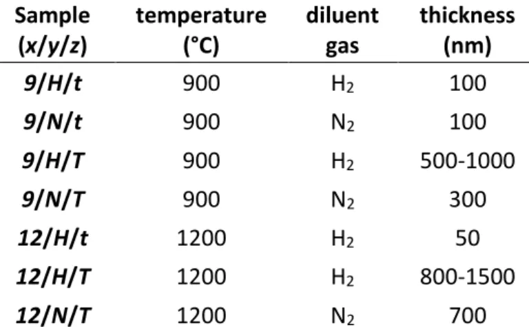
The samples are named by the triplets (x/y/z) according to the synthesis conditions and the thickness of the BN interphases. x stands for the infiltration temperature and takes the value 9 or 12 for 900 °C and 1200 °C respectively. y stands for the diluent gas used, H for H2 and N for N2. z stands for the
thickness of the interphase using the lower case letter t for a thi i terphase or the upper ase letter
Tfor a thi k i terphase. The differe t ases are prese ted i Table 1.
Sample
(x/y/z)
temperature
(°C)
diluent
gas
thickness
(nm)
9/H/t
900
H
2100
9/N/t
900
N
2100
9/H/T
900
H
2500-1000
9/N/T
900
N
2300
12/H/t
1200
H
250
12/H/T
1200
H
2800-1500
12/N/T
1200
N
2700
Table 1. Name and corresponding CVI temperature, CVI diluent gas and interphase thickness for each
sample
3.1 General microstructural organization of coatings.
The pairs of values (OA,Lc) measured for coatings deposited at 900 °C and 1200 °C and with the two
diluent gases (H2 and N2) as well as the SAED patterns of those obtained with H2 are shown in a diagram
in Fig. 1. Temperature has a significant effect on the microstructure of BN. Coatings deposited at 900 °C are quasi isotropic and barely crystallized, whereas coatings deposited at 1200 °C exhibit high structural anisotropy and a higher degree of crystallization. Crystallization of sp2-BN directly obtained
by raising the deposition temperature is well established [7] whereas the diluent gas effect is less obvious. It nevertheless appears that N2 is more favourable than H2 for the organisation of the coating,
particularly at 1200 °C. A similar effect was observed by Carminati et al. comparing Ar and H2 diluent
gases [14]. Based on chemical analyses of the gas phase, the authors explain that an interaction between H2 and the boron precursor (BCl3) promotes the formation of an effective or intermediate
4
Fig. 1. OA and Lc microstructural parameters calculated from SAED patterns for 9/H/T, 9/N/T, 12/H/T and 12/N/T BN samples and SAED patterns for 9/H/T (green frame) and 12/H/T BN samples (red frame)
3.2 BN interphases synthesized at 1200 °C
The DF image of coating 12/H/T displays an overall low contrast (Fig. 2a
).
However, this contrast is locally more pronounced, showing the presence of highly bright coherent domains which can reach a size of several tens of nanometres. These domains, which appear only in thick interphases, are often triangular in shape (Fig. 2b) but can also display other shapes such as a plate-like shape (Fig. 2c)
. The SAED pattern (Fig. 1) is typical of a turbostratic material with an overall structural anisotropy (illustrated by arcs). In addition to the structural heterogeneity, HRTEM observations confirm the structural anisotropy with a preferential orientation of the sp2-BN basal atomic layers globally parallelto the fibre surface throughout the coating. More precisely, at the interface between the fibre and the interphase, the first deposited atomic layers follow the roughness of the fibre (Fig. 3a). Additional spots in the SAED arcs reveal the presence of crystalline sp2-BN domains in addition to the surrounding
turbostratic arrangement, i.e. the coherent domains that illuminate in DF mode. The lattice fringes show that the basal planes of sp2-BN are locally very straight and well aligned with respect to each
other, although lenticular cracks may locally separate them in these large crystallites (Fig. 3b). On the edge of a triangular domain, the arrangement of the fringes reflects a marked structural heterogeneity (Fig. 3c). On the right side are the straight and well-stacked fringes whereas, on the left side, are the tortuous and disorganized fringes. There is a structural continuity between the two areas, the atomic layers of t-BN are locally very deformed but ensure the junction with the straight basal planes of crystalline sp2-BN. This heterogeneous character of the sp2-BN microstructure has already been
observed in CVI [17] or CVD [14] coatings and structural defects at the interface between poorly and highly organized areas have been described [18].
6 9/H/T OA ( ) Lc (n m ) 20 40 60 80 100 2 3 4 5 9/N/T 12/N/T 12/H/T 900 C 1200 C
5
Fig. 2. (a) DF images of a BN interphase synthesized at 1200 °C with H2 (12/H/T sample), enlarged images of (b) a crystallite of triangular shape and (c) a plate-like crystallite
Fig. 3. Filtered HRTEM images of (a) the fibre-interphase interface in 12/H/t sample, (b) lenticular cracks and (c) edge of a crystallite in 12/H/T sample
(a)
(b)
fibre
interphase
matrix
(c)
(a)
(b)
(c)
fibre
interphase
6
This feature is different from the structural organization of laminar PyCs. The pair of values (OA,Lc) for
the sp2-BN synthesized at 1200 °C is, in the present study, similar to that of the rough or regenerative
laminar PyC (Fig. 1) [19]. However, the microstructure of these classes of PyCs is homogeneous, without crystalline domains. The triangular crystallites observed in sp2-BN may suggest the growth
cones observed in regenerated pyrocarbon. But, the TEM observations made here only in cross-section do not allow to determine their exact 3D shape. Moreover, unlike the sp2-BN crystallites which might
be faceted, the regenerative PyC growth cones keep a turbostratic nature. Consequently, there are no spots in the continuous 00.2 arcs in PyC SAED patterns. The degrees of structural organization and of crystallization of a material deposited by CVD depend on the precursor system and on the processing conditions used. But, although carbon and boron nitride are isoelectronic materials, differences in electronegativity exist between boron and nitrogen atoms in the former and, of course, not between carbon atoms in the latter. This plays a role on the van der Waals and electrostatic interactions which are themselves involved in the stacking of the basal atomic monolayers [20] [21] [22]. The nature and the existence of crystallographic defects (vacancies, grain boundary dislocations, topological defects) that may exist in the basal layers depend on the material under consideration [23] [24] [25]. They can thus also be at the origin of the differences encountered in the microstructures of PyC and sp2-BN.
According to the values (OA,Lc), the use of N2 diluent gas instead of H2 better promotes the anisotropy
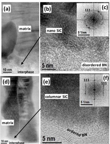
and crystallization of BN (Fig. 1). Besides, the triangular crystallites are larger in the sample 12/N/T than in the sample 12/H/T (Fig. 4a). Some are submicronic, yet large enough to obtain good quality SAED patterns from them alone with the microscope used. The SAED patterns are spotted, confirming that these crystallites consist of three-dimensionally ordered BN and not turbostratic BN. The sp2-BN
basal planes are always parallel to the direct electron beam (the spot associated with the 0.33 nm interreticular distance is always present on the obtained SAED patterns) because of the preferential orientation of the coating, but the zone axis may vary from one crystallite to another. Fig. 4b shows a typical SAED pattern repeatedly obtained. It corresponds to the triangular crystallite shown in Fig. 4a (the area selected for diffraction being totally included in the crystallite). It can only be indexed as a rhombohedral BN crystal with [01.0] zone axis (with indexing using hexagonal crystallographic axes), as in the work of Oku et al. [26]. As indexing a hexagonal BN crystal is not possible, a SAED pattern of a sp2-BN crystal taken along such a zone axis avoids the confusion between r-BN and h-BN that is
usually possible with other zone axes. Weak diffuse streaks are also visible between the Bragg reflection spots 10.3l+1 and -10.3l+1 along c* direction, indicating the presence of crystallographic stacking faults. Such stacking faults have already been reported in sp2-BN crystals [26] [27] [28].
In the coatings deposited at 1200 °C with H2 diluent gas, the crystal domains are too small to achieve
suitable SAED patterns. However, some of the HRTEM observations (Fig. 4c) can be sufficiently analysed to determine the crystallographic structure of BN. The corresponding FFT model (Fig. 4d) is similar to the SAED pattern obtained from the coating deposited with N2 (Fig. 4b). It therefore also
7
Fig. 4. (a) BF image and (b) SAED pattern of a r-BN crystallite taken along [01.0] zone axis in 12/N/T sample, (c) HRTEM image of a r-BN crystallite taken along [01.0] zone axis in 12/H/T sample and (d) FFT taken in an area (red square) of (c)
The rhombohedral polytype is identified in the best crystallized domains of the interphase coatings developed in this study. This result is in agreement with the calculations of Pedersen et al. which indicate that r-BN is the most stable polytype under CVD conditions similar to those used here for CVI of sp2-BN thin films [29]. Matsuda et al. and Oku et al. indicated that they obtained r-BN included in
CVD coatings deposited from NH3 and BCl3 on graphite substrates at 1500-1600 °C [30] [26]. But this is
the first time that the presence of r-BN is evidenced in an interphase obtained by CVI in a CMC using the same precursors than those used at lower temperatures. BN interphases are usually entirely turbostratic, more or less organized but without crystalline domain. Cases where three-dimensionally crystallized domains occur in BN interphases for CMCs are rare. This mainly concerns coatings deposited on a single fibre or a single fibre tow from other precursors such as BF3 and NH3 [31] [32]
[17] or tris(dimethylamino)borane [18]. In addition, the precise sp2-BN polytype may be difficult to
determine accurately [33], especially if it has not been observed by TEM with a suitable zone axis.
3.3 BN interphases synthesized at 900 °C
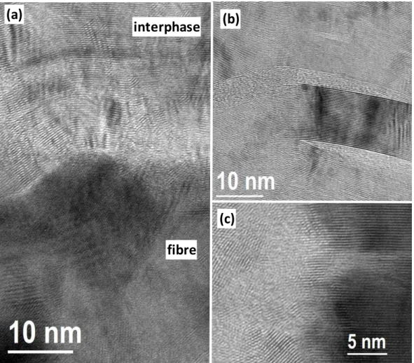
BN interphases synthesized at 900 °C are very poorly crystallized and have a quasi-isotropic microstructure. Contrary to the previous case, the arcs of the SAED pattern are diffuse, broader and seem to join together to almost form a ring (OA = 75-95°) (Fig. 1). The DF image of the 9/N/t coating is low in contrast and homogeneous, even locally, and finely spotted (Fig. 5a). HRTEM images show
(a)
(b)
00.3 10.1(c)
(d)
00.3 10.18
coherent domains consisting of a stack of a few distorted basal layers less than five nanometres in size (Fig. 5b) corresponding to the small bright spots in the dark field images. This microstructure is similar to that of dark laminar PyC [34]. An illuminated narrow strip is also located along the interface between the fibre and the interphase in DF images (Fig. 5a). This corresponds to the first basal layers of sp2-BN
that are deposited on the fibre and arranged almost parallel to the surface as shown by the HRTEM observations (Fig. 5c). They develop a local structural anisotropy before losing it in the rest of the coating. This feature has already been observed in BN interphases [35] [36].
Fig. 5. TEM observations of 9/N/t sample: (a) DF image, (b-d) HRTEM images of the interphase, the fibre-interphase interface area and a BN crystallite, respectively
In the majority of the coating, poorly organized, the coherent domains are so small that they can superimpose in the thickness of the thin foil crossed by the electron beam of the microscope. Despite this issue, for the coherent domain of the sample 9/N/t observed in Fig. 5d, the local conditions were favourable enough to resolve individual atom columns in projection. The existence of such crystallites, although very small, with a 3-dimensional order in a coating prepared at a temperature as low as 900 °C may be due to the rise in temperature occurring during the infiltration of molten silicon into the matrix. In the high-magnification filtered HRTEM image in Fig. 5d, the sp2-BN crystallite is observed in an
orientation that, according to Chubarov et al., should allow the differentiation of r-BN and h-BN [33]. However, a variable distortion depending on the portion of the crystallite under consideration is noticeable due to a variable stacking disorder of the planes. Because of the very high degree of these distortions in addition to some misalignments due to image acquisition limitations, determining conclusively the nature of the observed sp2-BN polytype is difficult.
(a)
interphase
fibre matrix(b)
(c)
fibre
interphase
(d)
9 3.4 Interface between BN interphase and SiC matrix.
In every cases, the CVI SiC matrix has a columnar structure and the interface between the BN interphase and the SiC matrix is cohesive (Fig. 6). But the microstructure of SiC in its early stages of growth is influenced by the surface of the underneath BN interphase.
Fig. 6. BF images of the SiC matrix and the interface with the BN interphase in (a) 9/H/T, (b) 12/H/t, (c) 12/H/T and (d) 12/N/T sample
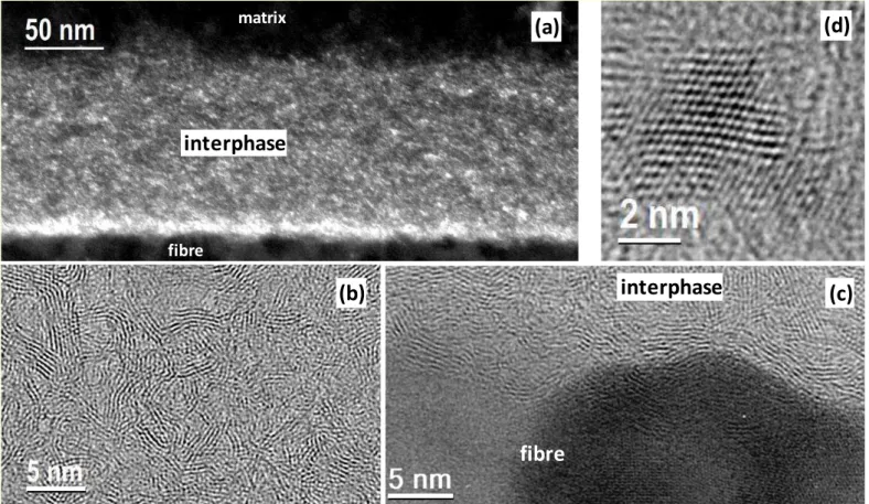
In the case of a poorly crystallized BN interphase synthesized at 900 °C, and whatever its thickness, the surface of the coating is smooth. Furthermore, because of the structural isotropy, many edges of sp2
-BN layers appear as shown in Fig. 7b. These are sites promoting the nucleation of SiC grains. As a result, a first equiaxed layer is deposited on the interphase (Figs. 6a & 7ab). It is composed of fine and non-oriented SiC grains, as shown by the FFT in Fig. 7c that consists of a ring of spots at the 111 distance of
(a)
(c)
(d)
interphase matrix interphase(b)
interphase matrix matrix interphase matrix equiaxed SiC layer10
3C-SiC (0.252 nm). Then the structure of the SiC matrix changes. It consists of columnar grains of preferential orientation which grow from the first nucleated, equiaxed layer deposited on the interphase according to the growth model proposed by van der Drift [37].
Fig. 7. HRTEM observations of the SiC matrix and the interface with the BN interphase. (a) 9/H/t sample, (b) filtered detail of (a) and (c) FFT of (b). (d) 12/H/t sample, (e) filtered detail of (d) and (f) FFT of (e)
In the case of a highly crystallized interphase synthesized at 1200 °C, because of the strong structural anisotropy, few edges of sp2-BN basal layers emerge at the surface (Fig. 7e). The density of active sites
promoting the nucleation of SiC is therefore limited. The columnar SiC grains with (111) texture grow directly on the BN coating without an equiaxed interlayer (Fig. 7d). The FFT of the early growth zone corresponds to a faulted 3C-SiC crystal oriented along [110] zone axis (Fig. 7f). If the BN interphase is thin (sample 12/H/t), its surface is smooth and the SiC columns are well oriented (Fig. 6b). If the interphase synthesized at 1200 °C becomes thicker, triangular crystallites of r-BN appear within the t-BN. The larger these crystallites are, the rougher becomes the surface of the coating. This roughness affects the columnar growth of SiC by disorienting the columns from each other. The SiC columns are more disoriented in sample 12/N/T (Fig. 6d) than in sample 12/H/T (Fig. 6c) due to the larger size of the triangular crystallites of r-BN. The disorientation of the columns extends in the SiC matrix over several micrometres in thickness.
Schematic representations which summarize the different microstructures encountered in the BN interphases and at the interfaces with fibre and matrix are given in Fig. 8.
(d)
(e)
(a)
(b)
111(c)
disordered BN interphase nano SiC columnar SiC matrix matrix interphase(f)
111 11111
Fig. 8. Schematic representations of BN interphases and interfaces with SiC fibre (bottom) and SiC matrix (top) for (a) an interphase synthesized at 900 °C, (b) a thin interphase synthesized at 1200 °C and (c) a thick interphase synthesized at 1200 °C
4. Conclusion
BN interphases were synthesized by CVI at two different temperatures in preforms made of a single 2D SiC fibre woven fabric and characterized by TEM. At 900 °C as well as at 1200 °C, the first basal layers of sp2-BN are deposited parallel to the surface of the fibre, following its roughness.
When the CVI is performed at 900 °C, whatever their thickness, the obtained BN interphases are very poorly crystallized and exhibit a quasi-isotropic microstructure. This t-BN microstructure favours the nucleation of small SiC grains during the subsequent CVI of the matrix. An equiaxed interlayer is then obtained before the columnar growth of the SiC matrix.
If the CVI is performed at 1200 °C, the obtained interphases exhibit strong structural anisotropy. For an interphase thickness of less than 300 nm, the microstructure corresponds to highly organized t-BN. The columnar SiC grains with (111) texture grow directly on the smooth thin BN coating without an equiaxed interlayer. From 300 nm interphase thickness, triangular crystallites of r-BN appear within the t-BN. The roughness resulting from the highly crystallized but heterogeneously structured interphase disorients the growth of the SiC matrix columns.
The mechanical characterization of single-ply SiC/SiC-Si composites with these different BN interphases will be carried out in a further work.
Acknowledgements
This work was supported by SAFRAN CERAMICS through a PhD grant given to H. Delpouve.
(a)
(b)
(c)
SiC
SiC
SiC
SiC SiC SiC
BN
BN
12
References
[1] N. Izyumskaya, D.O. Demchenko, S.Das, Ü. Özgür, V. Avrutin, H. Morkoç, Recent development of boron nitride towards electronic applications, Adv. Electron. Mater. 3 (2017) 1600485, https://doi.org/10.1002/aelm.201600485
[2] J. Eichler, C. Lesniak, Boron nitride (BN) and BN composites for high-temperature applications, J. Eur. Ceram. Soc. 28 (2008) 1105–1109, https://doi.org/10.1016/j.jeurceramsoc.2007.09.005
[3] R. Naslain, The design of the fibre-matrix interfacial zone in ceramic matrix composites, Compos. A: Appl. Sci. Manuf. 29 (1998) 1145–1155, https://doi.org/10.1016/S1359-835X(97)00128-0
[4] R. Naslain, Design, preparation and properties of non-oxide CMCs for application in engines and nuclear reactors: an overview, Compos. Sci. Technol. 64 (2004) 155-170, https://doi.org/10.1016/S0266-3538(03)00230-6
[5] G.N. Morscher, H.M. Yun, J.A. Dicarlo, L.T. Ogbuji, Effect of a boron nitride interphase that debonds between the interphase and the matrix in SiC/SiC composites, J. Am. Ceram. Soc. 87 (2004) 104–112, https://doi.org/10.1111/j.1551-2916.2004.00104.x
[6] S. Dong, Z. Wang, H. Zhou, Y.-M. Kan, X. Zhang, Y. Ding, Le Gao, Bin Wu, J. Hu, Research Progress in SiC-Based Ceramic Matrix Composites, J. Korean Ceram. Soc. 49 (2012) 295-300, https://doi.org/10.4191/kcers.2012.49.4.295
[7] J. Dai, Y. Wang, Z. Xu, R. Mu, L. He, Effect of temperature on the growth of boron nitride interfacial coatings on SiC fibers by chemical vapor infiltration, Ceram. Int. 45 (2019) 18556–18562, https://doi.org/10.1016/j.ceramint.2019.06.077
[8] V. Cholet, L. Vandenbulcke, Chemical vapor infiltration of boron nitride interphase in ceramic fiber preforms: discussion of some aspects of the fundamentals of the isothermal chemical vapor infiltration process, J. Am. Ceram. Soc. 76 (1993) 2846-2858, http://dx.doi.org/10.1111/j.1151-2916.1993.tb04026.x
[9] M. Leparoux, L. Vandenbulcke, C. Clinard, Influence of isothermal chemical vapor deposition and chemical vapor infiltration conditions on the deposition kinetics and structure of boron nitride, J. Am. Ceram. Soc. 82 (1999) 1187-1195, http://dx.doi.org/10.1111/j.1151-2916.1999.tb01894.x
[10] A. Udayakumar, A. Sri Ganesh, S. Raja, M. Balasubramanian, Effect of intermediate heat treatment on mechanical properties of SiCf/SiC composites with BN interphase prepared by ICVI, J. Eur. Ceram.
Soc. 31 (2011) 1145–1153, http://dx.doi.org/10.1016/j.jeurceramsoc.2010.12.018
[11] J. Thomas, N.E. Weston, T.E. O'Connor, Turbostratic1 boron nitride, thermal transformation to
ordered-layer-lattice boron nitride, J. Am. Chem. Soc. 84 (1962) 4619–4622, https://doi.org/10.1021/ja00883a001
[12] R. Naslain, J. Lamon, R. Pailler, X. Bourrat, A. Guette, F. Langlais, Micro/minicomposites: a useful approach to the design and development of non-oxide CMCs, Composites: Part A 30 (1999) 537–547, https://doi.org/10.1016/S1359-835X(98)00147-X
[13] J. Steibel, Ceramic matrix composites taking flight at GE Aviation, Am. Ceram. Soc. Bull., 98 [no. 3] (2019) 30–33, https://ceramics.org/wp-content/uploads/2019/03/April-2019_Feature.pdf
[14] P. Carminati, T. Buffeteau, N. Daugey, G. Chollon, F. Rebillat, S. Jacques, Low pressure chemical vapour deposition of BN: Relationship between gas phase chemistry and coating microstructure, Thin Solid Films 664 (2018) 106 114, https://doi.org/10.1016/j.tsf.2018.08.020
[15] X. Bourrat, B. Trouvat, G. Limousin, G. Vignoles, F. Doux, Pyrocarbon anisotropy as measured by electron diffraction and polarized light, J. Mater. Res. 15 (2000) 92-101, http://doi.org/10.1557/JMR.2000.0017
[16] P. Scherrer,
Bestimmung der Grösse und der inneren Struktur von Kolloidteilchen mittels
Röntgensrahlen,
Nach Ges Wiss Göttingen, Math-Phys Kl. (1918) 98-100.[17] S. Jacques, A. Lopez Marure, C. Vincent, H. Vincent, J. Bouix, SiC/SiC minicomposites with structure graded BN interphases, J Eur. Ceram. Soc. 20 (2000) 1929 1938, http://dx.doi.org/10.1016/S0955-2219(00)00064-9
[18] C. Lorrette, P. Weisbecker, S. Jacques, R. Pailler, J.-M. Goyhénèche, Deposition and characterization of hex-BN coating on carbon fibres using tris(dimethylamino)borane precursor, J. Eur. Ceram. Soc. 27 (2007) 2737-2743, http://dx.doi.org/10.1016/j.jeurceramsoc.2006.10.010
13
[19] J.-M. Vallerot, X. Bourrat, A. Mouchon, G. Chollon, Quantitative structural and textural assessment of laminar pyrocarbons through Raman spectroscopy, electron diffraction and few other techniques, Carbon 44 (2006) 1833-1844, https://doi.org/10.1016/j.carbon.2005.12.029
[20] N. Marom, J. Bernstein, J. Garel, A. Tkatchenko, E. Joselevich, L. Kronik, O. Hod, Stacking and registry effects in layered materials: the case of hexagonal boron nitride, Phys. Rev. Lett. 105 (2010) 046801, https://doi.org/10.1103/PhysRevLett.105.046801
[21] O. Hod, Graphite and Hexagonal Boron-Nitride have the Same Interlayer Distance. Why? J. Chem. Theory Comput. 8 (2012) 1360–1369, https://doi.org/10.1021/ct200880m
[22] G. Constantinescu, A. Kuc, T. Heine, Stacking in bulk and bilayer hexagonal boron nitride, Phys. Rev. Lett. 111 (2013) 036104, https://doi.org/10.1103/PhysRevLett.111.036104
[23] G.J. Slotman, A. Fasolino, Structure, stability and defects of single layer hexagonal BN in comparison to graphene, J. Phys.: Condens. Matter 25 (2013) 045009, https://doi.org/10.1088/0953-8984/25/4/045009
[24] A. Pakdel, Y. Bando D. Golberg, Nano boron nitride flatland, Chem. Soc. Rev. 43 (2014) 934-959, https://doi.org/10.1039/C3CS60260E
[25] M. Li, T. Deng, B. Zheng, Y. Zhang, Y. Liao, H. Zhou, Effect of defects on the mechanical and thermal properties of graphene, Nanomaterials, 9 (2019) 347, https://doi.org/10.3390/nano9030347
[26] T. Oku, K. Hiraga, T. Matsuda, T. Hirai, M. Hirabayashi, Twin structures of rhombohedral and cubic boron nitride prepared by chemical vapor deposition method, Diam. Relat. Mater. 12 (2003) 1138– 1145, https://doi.org/10.1016/S0925-9635(02)00329-1
[27] S. Turan, K.M. Knowles. High resolution transmission electron microscopy of the planar defect structure of hexagonal boron nitride. phys. stat. sol. (a), 150 (1995) 227-237, https://doi.org/10.1002/pssa.2211500120
[28] J.Y. Huang, H. Yasuda, H. Mori, HRTEM and EELS Studies on the amorphization of hexagonal boron itride i du ed y all illi g J. A . Cera . Soc. 83 (2000) 403–09, https://doi.org/10.1111/j.1151-2916.2000.tb01204.x
[29] H. Pedersen, B. Alling, H. Högberg, A. Ektarawong, Thermodynamic stability of hexagonal and rhombohedral boron nitride under chemical vapor deposition conditions from van der Waals corrected first principles calculations, J. Vac. Sci. Technol. A 37 (2019) 040603, https://doi.org/10.1116/1.5107455
[30] T. Matsuda, N. Uno, H. Nakae, T. Hirai, Synthesis and structure of chemically vapour-deposited boron nitride, J. Mater. Sci. 21 (1986) 649-658, https://doi.org/10.1007/BF01145537
[31] F. Rebillat, A. Guette, R. Nasiain, C. Robin Brosse, Highly ordered pyrolytic BN obtained by LPCVD, J. Eur. Ceram. Soc. 17 (1997) 1403-1414, https://doi.org/10.1016/S0955-2219(96)00244-0
[32] F. Rebillat, A. Guette, L. Espitalier, C. Debieuvre, R. Naslain, Oxidation resistance of SiC/SiC micro and minicomposites with a highly crystallised BN interphase, J. Eur. Ceram. Soc. 18 (1998) 1809-1819, https://doi.org/10.1016/S0955-2219(98)00120-4
[33] M. Chubarov, H. Högberg, A. Henry, H. Pedersen, Review Article: Challenge in determining the crystal structure of epitaxial 0001 oriented sp2-BN films, J. Vac. Sci. Technol. A 36 (2018) 030801,
https://doi.org/10.1116/1.5024314
[34] X. Bourrat, F. Langlais, G. Chollon, G.L. Vignoles, Low temperature pyrocarbons: A review, J. Braz. Chem. Soc. 17 (2006) 1090-1095, https://doi.org/10.1590/S0103-50532006000600005
[35] O. Dugne, S. Prouhet, A. Guette, R. Naslain, R. Fourmeaux, Y. Khin, J. Sevely, J.P. Rocher, J. Cotteret, Interface characterization by TEM, AES and SIMS in tough SiC (ex-PCS) fibre-SiC (CVI) matrix composites with a BN interphase, J. Mater. Sci. 28 (1993) 3409-3422, https://doi.org/10.1007/BF01159815
[36] S. Le Gallet, F. Rebillat, A. Guette, X. Bourrat, F. Doux, Influence of a multilayered matrix on the lifetime of SiC/BN/SiC minicomposites. J. Mater. Sci. 39 (2004) 2089–2097, https://doi.org/10.1023/B:JMSC.0000017771.93067.42
[37] A. Van der Drift, Evolutionary selection, a principle governing growth orientation in vapour-deposited layers, Philips Res. Repts 22 (1967) 267–288.