THE CATALYZED LIQUEFACTION AND GASIFICATION OF COAL
by
George T. Wildman
B,S., University of New Hampshire
(1957)
M.S., New York University
(1962)
Submitted in Partial Fulfillment of the Requirements for the .Degree of Doctor of Science
at the
MASSACHUSETTS INSTITUTE OF TECHNOLOGY
May, 1973
Signature of Author: ..
A.
... ... Depar,&ent of Chemical Engineering,May .4, 1973
Certified by: .... ...
,Thesis Supervisor
'
Accepted by: ...Chairman,
Departmental Cnmmittee on Graduate Theses
ABSTRACT
THE CATALYZED LIQUEFACTION AND GASIFICATION OF COAL
by
George T. Wildman
Submitted to the Department of Chemical Engineering on May 4, 1973,
in partial fulfillment of the requirements for the degree of
Doctor of Science
A study of one-step processes for the liquefaction of coal with water has been made at temperatures of 350 to 4650C and pressures up to 8000 psig with and without cata-lysts and a deliberately added liquid phase. The coal
(30 grams) used was a Pittsburgh Seam coal (H/C = 0.803). The catalysts were commercial catalysts selected because their known catalytic functions were possibly desirable for promoting the water-coal reaction. Either phenanthrene
(30 grams), Decalin (60 ml) or Tetralin (60 ml) was the deliberately added phase. Experiments were made in a 300 ml rocking autoclave. Usual reaction times were two hours (not including heating and cooling times). Coal
conversion was defined as the coal charge less the benzene-extracted residue divided by the coal charge, all on the dry basis, times 100.
Coal conversions were 16 to 20% in the water-coal system vis
A
vis 10 to 11% when coal was heated with nitrogen present. Catalysts such as cobalt molybdate on alumina and cobalt-thoria on kieselguhr had no apparent effect on the water-coal reaction.An improvement (to 25% w/w) in coal conversion occurred when phenanthrene was added to the water-coal system. Again catalysts had no appreciable effect. Coal conversions in-creased to 30 to 31 w/w when Decalin was added to the water-coal system. Catalysts, such as nickel tungsten on alumina and cobalt molybdate on alumina may have increased
coal conversion slightly in the latter system. Tetralin liquefied about 65 to 67% of the coal. When coal was
treated with Tetralin and water, coal conversion dropped to 59 to 61% and when catalysts were also used, coal conver-sions were 49 to 51%.
These results were satisfactorily explained by two kinetic models. One model assumed that stabilization of the coal-derived active fragments (produced via thermal
cracking) to benzene solubles occurred chiefly by rearrange-ment reactions, and to benzene insolubles by polymerization. The other kinetic model assumed stabilization to benzene solubles occurred mainly by hydrogen transfer from a liquid donor agent and to benzene insolubles by polymerization. The model without hydrogen transfer was applicable to the water-coal and phenanthrene-water-coal systems. The model with hydrogen transfer was applicable to the Tetralin-coal and Tetralin-water-coal systems. Both hydrogen transfer and rearrangement reactions were probably important in the Decalin-containing runs.
Subsequently, a study was made to determine if the residual cokes would gasify at a practical rate at 1000OF
(5380C) and atmospheric pressure using potassium and cesium salts as catalysts in the ratio of 0.002 g.-atom alkali cation per g. coke. Experiments were made in a 1" I.D. tubular reactor operated continuously with respect to steam (downflowI and batch in carbon.
Gasification rates (RI) generally first increased as the fraction carbon gasified (FCG) increased, then decreased. The exact shapes of the RI curves varied de-pending on the catalyst and its initial distribution in the bed. When cesium acetate was mixed with the top third of the bed, RI increased at higher FCG values. The gaseous
products (dry basis) were hydrogen (70%) and carbon dioxide (29%). Maximum RI values at 10000F obtained with the catalysts, cesium acetate potassium acetate and potassium carbonate were 8.95x10⁻⁴, 4.7 x10⁻⁴ and 5 x 10⁻⁴ g.C/(min.) (g.C), respectively. These are about 20 and 10%, respectively, of the commercially feasible rate at 15000F (50 x10-4 g.C/(min.)(g.C)). The RI drop with FCG for the volatile cesium and potassium acetates was attributed to catalyst loss; the RI drop for potassium carbonate was attributed to its low mobility.
Thesis Supervisors: 1. Edwin R. Gilliland*
2. Charles N. Satterfield+* Titles: 1. Institute Professor and Warren K. Lewis
Professor of Chemical Engineering 2. Professor of Chemical Engineering + Died March 10, 1973
Department of Chemical Engineering Massachusetts Institute of Technology Cambridge, Massachusetts 02139
May 4,
1973
Professor David B. Ralston Secretary of the Faculty
Massachusetts Institute of Technology Cambridge, Massachusetts 02139
Dear Professor Ralston:
In accordance with the regulations of the Faculty, I herewith submit a thesis, entitled "The Catalyzed Liquefaction and Gasification of Coal" in partial ful-fillment of the requirements for the degree of Doctor
of Science in Chemical Engineering at the Massachusetts Institute of Technology.
Respectfully submitted,
ACKNOWLEDGEMENTS
This research was proposed and directed by
Professor Edwin R. Gilliland who died on March 10, 1973 while the final editing of the manuscript was in progress. The author wishes to acknowledge the indelible impres-sions that this brilliant and accomplished man made as a practicing engineer, professor, thesis advisor and friend over a fifteen year association.
The author wishes to express his appreciation to Professor Charles N. Satterfield for graciously assuming the unexpected task of thesis advisor and for helpful suggestions on interpretation and format.
The author wishes to thank the following individuals: William R. Davis, for invaluable assistance in
the experimentation and analysis of data. Arthur S. Wildman, Jr., for invaluable
assistance during the duration of the research.
William A. Heath and Dale A. Jones, for assistance and helpful discussions in
the initial stages of the research. Jerome F. Mayer, for helpful discussions on
interpretation and for editing assistance Everett Gorin and the Consolidation Coal Co.
Stanley R. Mitchell, for valuable help in
setting up equipment, for the technical drafting and printing of the final
manuscript.
Reed Fulton, Paul Bletzer and Al Merrill for equipment fabrication.
The author wishes to acknowledge the leave of absence and financial support granted by Merck & Co., Inc. which provided the opportunity to carry out this research. He further wishes to express his appreciation to his Merck associates, James Gillin, James Lago, Arnold Kaufman and William Sklarz, for their help and support.
The author also wishes to express his sincere appreciation to Miss Rita Pollard who assisted in organizing the material, typed the manuscript and generally made this portion of the effort much easier than it would otherwise have been.
TABLE OF CONTENTS Page ABSTRACT . 0 0 0 0 0 . 0 0. I. SUMMARY . . . . . . A. MOTIVATION . o . o . . . . 0 . 0 . 2 . . . . 20 o . . . . . . . o 20 B. OBJECTIVES . . . . . . . . C. CATALYZED LIQUEFACTION
OF COAL WITH WATER . . . . . .
1. Background . . ...
2. Program for Present Investigation 3. Experimental . . . . . . . .
4. Results of Coal
Liquefaction Studies ...
5. Interpretation of Coal
Liquefaction Results . . . . .
6. Conclusions from the Coal
Liquefaction Studies . . . . . 7. Recommendations for Future Work D. CATALYZED GASIFICATION OF COAL .
1. Background . . . . . . . .
2. Program for Present Investigation 3. Experimental . . . . . .
4, Results of Coal
Gasification Studies . . . . .
5. Interpretation of Coal
Gasification Results . . . . . 6. Conclusions from the Coal
Gasification Studies . . . . .
7. Recommendations for Future Work .
22 23 23 26 29 33 36 43 44
45
45 45 46 49 54 6o 63 . . .INTRODUCTION ... .. . A. "THE ENERGY CRISIS" . . . B. UTILIZATION OF COAL . . . .
C. PROBLEMS IN COAL CONVERSION
D. THERMAL EFFICIENCY OF THE TWO-STAGE PROCESSES . . . .
E. CHEMICAL STRUCTURE OF COAL . F. COAL LIQUEFACTION PROCESSES,
COMMERCIAL . . . .
G. COAL LIQUEFACTION PROCESSES, EXPERIMENTAL STUDIES . . . . H. MECHANISMS OF COAL CONVERSION
PROCESSES . . . . . . . I. RECAPITULATION . . . . . . . . * 0 0 0 0 * 0 0 6 6 * 0 0 0 6 * 0 0 6 0
Page
65 6567
71 75 78 84 98. . . . .
.
105
*. . . . .
108
J. REACTIONS BETWEEN CARBON AND WATER . K. DESIRED REACTIONS BETWEEN
COAL AND WATER . . . . . .
L. THERMODYNAMICS . . . .*
M. OBJECTIVES . . ... . . . .. N. PROGRAMS FOR PRESENT INVESTIGATION ... .
1. Coal Liquefaction Program 0 . . . 0 .
2. Residual Cokes Gasification Program . . . . II.
.
. .
110
112115
139140
140
146
· · · · · ·III. LIQUEFACTION SECTION . . . .
A. APPARATUS AND PROCEDURE,
LIQUEFACTION RUNS .. ...
1. Description of Liquefaction Equipment . . o . . . 2. Experimental Procedures
for Liquefaction Runs . . . 3. Analytical Methods .. o . B. PRESENTATION OF EXPERIMENTAL LIQUEFACTION RESULTS . . . .. 1. Background . . . . . . . 2. Tabulation of Liquefaction Experiments . * . 0 . . . 3. Presentation of Liquefaction Results . . * 0 0 0 0 0 0 0 0 0 * 0 0 0 0 * 0 0 0 0 * 0 0 * 0 * 0 0 0 0 * 9 0 0 0 * . 0 0 0 0 0 0 0 *
4. General Accuracy and Reproducibility C. DISCUSSION OF LIQUEFACTION RESULTS . .
1. Qualitative Observations
on Liquefaction Results . . . .
2. Interpretation and Analysis
of the Liquefaction Results . . . a. Water-Catalyst-Coal Systems . b. Phenanthrene-Water-Catalyst-Coal Systems . . . . . . . . c. Decalin-Water-Catalyst-Coal Systems . . . . . . . . d. Tetralin-Water-Catalyst-Coal Systems . . . . . . . . .
D. CONCLUSIONS FROM THE COAL
LIQUEFACTION STUDIES . . . . . . . . .
E. RECOMMENDATIONS FOR FUTURE WORK . . .
Page
148
148
148
150
154
156 156161
175
186
189
189
201201
214
220
225
238
240
. 0 O 0 . . O 0 O 0 O ~ 0 0IV. GASIFICATION SECTION . . . . . A. APPARATUS AND PROCEDURE,
GASIFICATION RUNS . . . . 1. Description of
Gasification Equipment . . . . . . 2. Experimental Procedures
for Gasification Runs . . . . 3. Analytical Methods . . . . B. PRESENTATION OF EXPERIMENTAL GASIFICATION RESULTS . . . . 1. Background . . . . 2. Tabulation of Gasification Experiments . . . . . . 3. Presentation of Gasification Results . . . . .
4. General Accuracy and Reproducibility C. DISCUSSION OF GASIFICATION RESULTS .
1. Qualitative Observations
on Gasification Results . . . . 2. Interpretation and Analysis
of the Gasification Results . .
a. Introduction . . . . b. Theoretical Background . . . . c. Comparisons of Actual and
Equilibrium Gas Compositions d. Shape of the RI vs. FCG Curves. e. Comparison of Observed
Gasi-fication Rates with those of Industrial Gasifiers . . . D. CONCLUSIONS FROM THE COAL
GASIFICATION STUDIES . . . . E. RECOMMENDATIONS FOR FUTURE WORK . . .
283
. ..285
288
S.•.
313
. . . 315
317
. . . 320
10 * . * * * 0 * 9 * 0 * 0 * 0 * 6 * 0 * 0 * 0 * 0 274 274 Page 241 241 241 248 250253
253
259 261 273. . 283
V. APPENDICES
APPENDIX I
A. LIQUEFACTION EQUIPMENT DETAILS 1. Liquefaction Reactors . . .
2. Rocker Assembly . . . . . .
3. Heaters . . . . 4. Equipment Layout . . . . .
B. GASIFICATION EQUIPMENT DETAILS 1. Gasification Reactor . . . 2. Water Vaporizer . . . . .. 3. Steam Condenser . . . . . . . . . . . . . . . . . . . . . . . . . . . . . . . . . . .. .. .. .. .. .. .. • • • • • • • • • • qt, • • • • • • e, • 4 • • • • APPENDIX II
VAPOR PHASE CHROMATOGRAPHIC ANALYSIS
OF GASIFICATION OFF-GASES . . . 336
APPENDIX III
GASIFICATION - SAMPLE CALCULATION . . . . . . 348
- COMPUTER PROGRAM. . . . . . . 374
APPENDIX IV
PHYSICAL PROPERTIES AND SOURCES OF CHEMICALS USED . . . . . .
LOCATION OF ORIGINAL DATA . . . .. LITERATURE CITED . . . . . BIOGRAPHICAL DATA . . . ... 0 0 S 378 384 385 390 11 Page 321 321 326 326 328 330 330 332 334
12 LIST OF FIGURES
Figure
1 Effect of Water and Polycyclic Hydrocarbons on Coal Conversion 2 Effect of Water, Polycyclic
Hydro-carbons and Heterogeneous Catalysts on Coal Conversion at 4100C . . .
3 Comparison of Alkali Salts for Water Coke Gasification at 10000P
(Catalysts Initially Distributed Throughout Bed) . . . . . . * 0 * 0 * 0 Page
34
35
51
4 Comparison of Alkali Salts for Water Coke Gasification at 10000F
(Catalysts Initially Distributed
in Top Third of Bed) . . . . . . . .
5 Schematic of the Two-Stage Processes 6 Equilibrium Constants for Possible
Reactions in Carbon-Steam System . 7 Equilibrium Composition 400.F
(Graphite-Steam System) . . . . . . .
8 Equilibrium Composition 600oF
(Graphite-Steam System) . . . . . . 9 Equilibrium Composition 8000F (Graphite-Steam System) . . . . . 10 Equilibrium Composition 900F1 (Graphite-Steam System) 11 Equilibrium Composition 10000F (Graphite-Steam System) .... . . . 12 Equilibrium Composition 12000F (Graphite-Steam System) 13 Equilibrium Composition 14000F (Graphite-Steam System) . . . . 14 Equilibrium Composition 18000F (Graphite-Steam System) 52
•
.
76
. .
119
S.
124
124
125
.
.
125
S.
126
0 . 126 0.
127
.
.
127
13
Page Figure
15 Effect of Temperature on
Graphite-Steam System (14.7 psi) 16 Effect of Temperature on
Graphite-Steam System (100 psi) 17 Effect of Temperature on
Graphite-Steam System (1000 psi)
18 Equilibrium Composition 9000F (Deposited Carbon-Steam System) 19 Equilibrium Composition 10000F
(Deposited Carbon-Steam System) . 20 Diagram of Batch Reactor for
Coal Liquefaction . o . . . .
128
128S.
129
..
S. . .
131
... . 131... .
149
21 Effect of Temperature on Coal Conversion
in Water-Catalyst-Coal Systems . . . . . 176 22 Effect of Temperature on Coal
Conversion in Phenanthrene-Water-Coal Systems . . . .
Effect of Temperature on Coal Conversion in Phenanthrene-Water-Catalyst-Coal Systems . . Effect of Temperature on Coal
Conversion in Decalin-Water-Coal Systems . . . . . ... Effect of Temperature on Coal
Conversion in Decalin-Water-Catalyst-Coal Systems . . . . . Effect of Temperature on Coal
Conversion in Tetralin-Water-Catalyst-Coal Systems . . . . . 27 Effect of Water and Polycyclic
Hydrocarbons on Coal Conversion Effect of Water, Polycyclic
Hydrocarbons and Heterogeneous Catalysts on Coal Conversion
at 4100C . . . . . .0 0
. . . . .
177
. . . . .
178
....
* 0179
. . . . .
180
*. . . .
181
S. . . .0 182
.
. . ..
183
23 24 25 26 28Figure
29.
30.
Diagram of Flow Reactor for
Gasification of Carbon with Steam Effect of Temperature on Decalin-W Coke Gasification . . . ..
ater
31 Comparison of Coke Reactivities at 10000F . ... . o o .
32 Effect of Potassium Carbonate Concentration on Water Coke
Gasification at 10000F 0 o . . . 33 Effect of Initial Potassium Acetate
Distribution and Devolatilization Procedure on Water Coke Gasification at 1000F . . . .
34 Comparison of Potassium Acetate with Potassium Carbonate for
Water Coke Gasification at 10000 . . 35 Effect of Initial Cesium Acetate
Distribution on Water Coke
Gasification at 1000F . . . .. .
36 Effect of Initial Cesium Nitrate Distribution on Water Coke
Gasification at 1000F . . . . . . . 37 Comparison of Potassium Acetate
with Cesium Acetate for Water
Coke Gasification at 10000F . . . . .
38 Comparison of Alkali Salts for Water Coke Gasification at 10000F
(Catalysts Initially Distributed Throughout Bed) . . . ..
39 Comparison of Alkali Salts for Water Coke Gasification at 10000F
(Catalysts Initially Distributed
in Top Third of Bed) . . . .
40 Comparison of Actual and Equilibrium Gas Compositions for Reaction GI, at 1000*F, RGl vs Time. Catalysts
Distributed Throughout Bed . . . .
14 Page . 242 262 263 . . 264 265 .. . 266 . . 267 268 . . 269 . 0 270 271 290 . .
Figure 41
42
Comparison of Actual and Equilibrium Gas Compositions for Reaction Gl, at 10000F, RG1 vs Time. Catalysts Distributed in Top Third of Bed . . .
Comparison of Actual and Equilibrium Gas Compositions for Reaction G2, at 10000F, RG2 vs Time. Catalysts Distributed Throughout Bed . • . . . . 43 Comparison of Actual and Equilibrium
Gas Compositions for Reaction G2, at 10000F, RG2 vs Time. Catalysts Distributed in Top Third of Bed . . . 44 Comparison of Actual and Equilibrium
Gas Compositions for Reaction GM, at 1000OF, RGM vs Time. Catalysts
Distributed Throughout Bed . . . . . . 45 Comparison of Actual and Equilibrium
Gas Compositions for Reaction GM, at 10000F, RGM vs Time. Catalysts Distributed in Top Third of Bed .. 46 Comparison of Actual and Equilibrium
Gas Compositions for Reaction S1, at 1000*F, R81 vs Time. Catalysts Distributed Throughout Bed ... 47 Comparison of Actual and Equilibrium
Gas Compositions for Reaction 81, at 10000F, RSI vs Time. Catalysts Distributed in Top Third of Bed . . . 48 Comparison of Actual and Equilibrium
Gas Compositions for Reaction S2, at 1000?F, RS2 vs Time. Catalysts Distributed Throughout Bed . . . .
49 Comparison of Actual and Equilibrium Gas Compositions for Reaction 82, at 10000F, RS2 vs Time. Catalysts Distributed in Top Third of Bed .
* . . 291 * . . 292 S. •. 293 . . . 294 S. •. 295 S. . 298 . . . 299 . . .
301
.
. . 302
15
16
Figure Page
50 Comparison of Actual and Equilibrium
Gas Compositions for Reaction M1,
at 1000*F, RM1 vs Time. Catalysts
Distributed Throughout Bed . . . . .
307
51 Comparison of Actual and Equilibrium Gas Compositions for Reaction MI, at 10000F, RM1 vs Time. Catalysts Distributed in Top Third of Bed . . . . .
308
52 Details of Reactor . . . . . 322
53 Details of Nickel-Lined Reactor . . . . . 324
54 Details of Cover for Nickel-Lined Reactor . . . . . . . . .
325
55 Reactor and Rocker Assembly . . .
327
56 Gasification Reactor Details . . . . . . 331
57 Details of Water Vaporizer . . . . 333
58
Details of Steam Condenser . . .335
59 Typical Chromatogram Obtained During Calibration . . . 341
60 Typical Chromatogram, Run G-13, Sample 6 ... . . 344
61 Cumulative Dry Gas Evolution' vs Elapsed Time, Run G-13 . . . . . . . 360
62 Condensate Weight vs Elapsed Time, Run G-13
.
... 36163 Gas Analysis vs Time for Run G-13 . . . . 362
64 Dry Gas Composition, Run G-13 . . . . 363
65 Component Outlet Rates, Run G-13 . . . . 364
66 Cumulative Production of Each Component, Carbon Gasified and Carbon Remaining as a Function of Time, Run
G-13.
. . . . . . . . 36517
Figure
67 Instantaneous Carbon Gasification
Rate vs Time, Run G-13 . . . . . . 366 68 Instantaneous Carbon Gasification
Rate vs Fraction of Original
Carbon Gasified, Run G-13 ° o a . . . . . 367
69 Comparison of Actual and Equilibrium Gas Compositions for Reactions GI, G2, S8 and GM at 1000OF with Cesium
Acetate Catalyst, Run G-13,
RG1
,RG
2, RS1, RGM vs Time . 0 . 0 . . . . 36870 Comparison of Actual and Equilibrium Gas Compositions for Reactions S2
and MI, at 10000F, with Cesium Acetate Catalyst, Run 0-13, RS2 vs Time and
RMl vs Time ...0 0 0 0 0 0 0 0 0 369 71 Comparison of Actual and Equilibrium
Gas Compositions for Reactions M2, M3 and M4, at 10000F with Cesium Acetate, Run G-13, RM2, RM3, RM4 vs
Time . . 0. . . .0 . .. . . . .
370
72 Comparison of Actual and Equilibrium Composition for Reactions G1, G2, Sl and GM, at 10000F, with Cesium Acetate,
Run G-13, RGl, RG2, RSI,
ROM
vs
FCG
. ..
371
73 Comparison of Actual and Equilibrium Gas Compositions for Reactions S2 and Ml, at 10000F with Cesium Acetate,
Run G-13, RS2 vs FCG and RM1 vs FCG . 372
74 Comparison of Actual and Equilibrium Gas Compositions for Reactions ME, M3 and N4, at 10000F with Cesium Acetate,
Run G-13,
RM2, RM3, Rm4 vs
FCG
0. . . .
373
75 Vapor Pressures of Phenanthrene,
18 LIST OF TABLES
Table Page
I Possible Desired Catalytic Functions
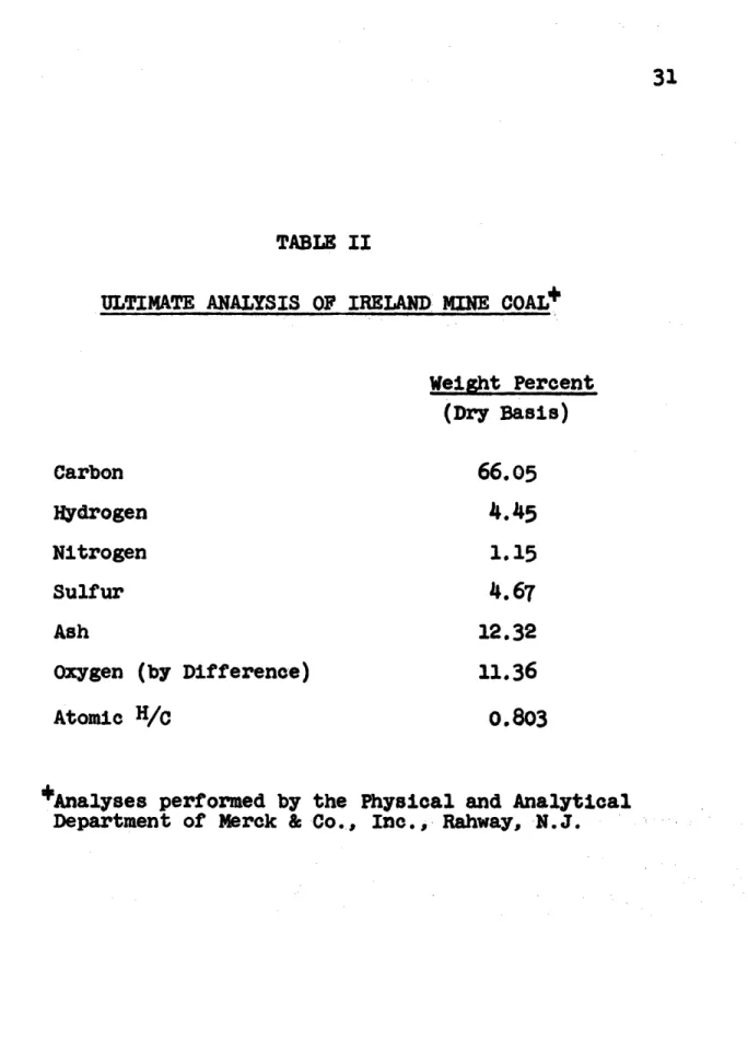
for Coal-Water System . ... .. 28 II Ultimate Analysis of Ireland
Mine Coal . . . . . . . . . . . . . . . . 31
III Chemical Composition of
Some Coals and Petroleum . . . . . . . 72
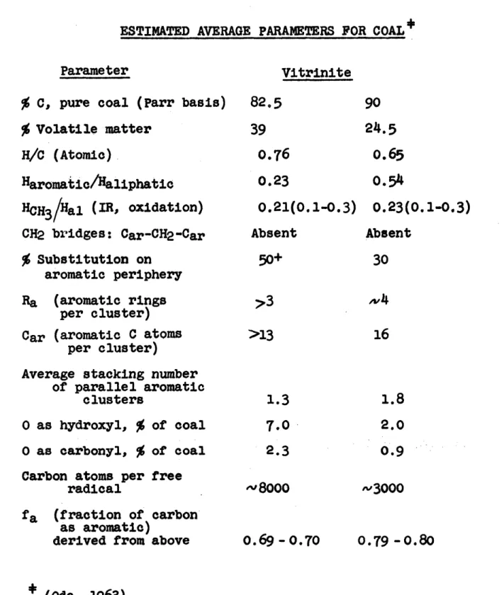
IV Estimated Average
Parameters for Coal ... 79
V Characteristic Minerals in Coal Ash . . . 83
VI Catalysts and Reaction Conditions for
Coal Hydrogenation, 1925 to 1953 . . 89
VII Effect of Vehicle in Hydrogenation
and Solvation of Coal . . .. ... 95
VIII Percentage of Methane in Product
Gas at Equilibrium at 10000F . . . 133 IX Standard Enthalpy Changes of
Possible Reactions in
Carbon-Steam System . . . . . . . . . . . 136 X Catalytic Processes in Which Water
Appears as Reactant or Product . . . . . . 143 XI Possible Desired Catalytic Functions
for Coal-Water System . . . . . . .. . . 144 XII Ultimate Analysis of
Ireland Mine Coal .. . . ... 157
XIII Tabulation of Water-Catalyst-Coal
Experiments . . . . . . . . . . . . . . 163 XIV Tabulation of
Phenanthrene-Water-Catalyst-Coal Experiments . . . . . . . . 165
XV Tabulation of
19
Table Page
XVI Tabulation of
Tetralin-Water-Catalyst-Coal Experiments . . . . . . . . 172 XVII Tabulation of
Phenanthrene-Water-Alkali Compound-Coal Experiments . . . . . 173 XVIII Tabulation of
Phenanthrene-Water-Carbon Monoxide-Catalyst-Coal
Experiments . . . . . . . . . . . . 174
XIX Ultimate Analyses of Typical Cokes . . . . 184
XX Calculated Compositions of
Coal-Derived Oils .. . . . 185
XXI Effects of Catalysts on Coal Conversion in the
Decalin-Water-Coal System . ... 196 XXII Ultimate Analysis of Decalin-Water
Coke and Water Coke Composites
Used in Gasification Experiments . . . . . 254
XXIII Ultimate Analysis of Devolatilized
Water Coke, Run G-18 . . . . . . . * . . . 256
XXIV Material Balance over Water Coke
Devolatilization, Run G-18 . . . . . . . . 257 XXV Tabulation of Gasification
Experiments . . . . . . . . . * . . . * 260 XXVI Cumulative Production of Gases . . . . 272
XXVII Possible Reactions in
Gasification Study . . ... . . 284 XXVIII Run G-13, Sample Calculation of
Dry Gas Composition ... .. . 345
XXIX Gas Composition as a Function
of Time for Run G-13 . . ... .... 347
XXX Steam Condensate Volume as a Function of
Elapsed Time from Start of Run G-13 . . . 357
XXXI Exit Gas Composition (Dry Basis)
Run G-13 . . . . 358
XXXII Exit Gas Composition (Dry
Nitrogen-Free Basis), Run G-13 . . . . 359
20 I. SUMMARY
A. MOTIVATION
United States projected demands for energy to the year 2000 indicate that there will soon develop a
short-age in the United States of our present major energy sources, petroleum and natural gas. Coal reserves, however, are enormous, constituting about 85% of the known recoverable fossil fuel in the United States. Nuclear power, now supplying a small fraction of the
total energy demand, will become a much larger factor. But, as long as the basis of the United States economy
remains the internal combustion engine, liquid fuels
will continue to be essential. Thus, the time is approach-ing in the Unhited States when coal will need to be con-verted on a gigantic scale, as it was in wartime Germany,
to synthetic fuels.
A coal-based synthetic fuels industry has never been established in the United States simply because it has always been cheaper to convert crude petroleum, rather than coal, to oil and gasoline. The expense in
coal conversion processes results from several factors, chief of which are the hydrogen deficiency of coal rela-tive to petroleum and the fact that coal, a solid having a high ash content, is inherently difficult to handle and
21 Low cost hydrogen is currently available from
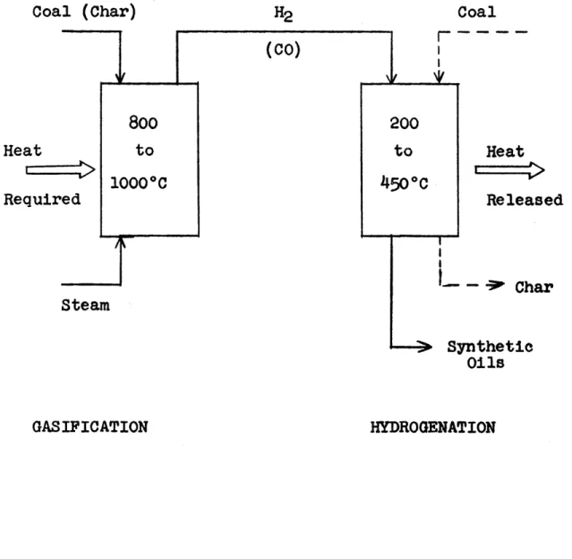
natural gas. However, this situation will not continue far into the future because of the rapid depletion of the natural gas reserves. It will probably become necessary to produce the hydrogen required for coal liquefaction by coal gasification which is normally a high temperature (800 to 10000C), highly endothermic process. Since the synthesis step in the two-step coal' conversion processes is a low temperature (250 to 4500C) exothermic process, the thermal efficiency of the com-bined gasification-synthesis steps is low, since the second law of thermodynamics prohibits the direct utilization of low temperature heat at a higher temperature.
22 B. OBJECTIVES
The objectives of this thesis were to develop solutions to these two fundamental problems in coal to synthetic fuels processes, the coal hydrogen deficiency relative to crude petroleum and the low thermal efficiency of the two-stage coal conversion processes. This thesis is divided into two sections, the first section, which represents the major portion of the present effort, is devoted to the study of methods for liquefying coal. The second section is concerned with studies on coal gasification.
The primary objective of the work described in the Liquefaction Section of this thesis was to find a set of conditions of temperature and pressure under which coal and water, with a suitable catalyst would react to produce liquids. The primary objective of the work described in the Gasification Section of this thesis was to determine if the char by-products from the lique-faction studies would gasify at a practical rate at 10000F using certain potassium and cesium salts as catalysts.
It is clear that the direct reaction of water
(the cheapest potential source of hydrogen) and coal to liquids would solve both of the fundamental process prob-lems, coal hydrogen deficiency and the low thermal effi-ciency of combined gasification-synthesis processes. Low temperature gasification only faces the thermal efficiency dilemma (hydrogen costs via coal gasification, however, would be reduced).
23
C. CATALYZED LIQUEFACTION OF COAL WITH WATER
1. Background
The thermodynamic analysis of the 0-graphite-steam system presented in the text shows that it is possible below 5000C to produce methane and the higher
hydro-carbons from reactions between carbon and water. Although, at equilibrium, the concentrations of the individual
hydrocarbons are extremely low, there are an infinite number of hydrocarbons and oxygenated hydrocarbons that could form, Thus, in the thermodynamic sense, formation
of an "oil" from the reaction of carbon and water is
feasible. Examples of these direct gasification-synthesis reactions are listed below.
1. Aliphatic hydrocarbon production
2C + 2H20 = CH4 + 002
70 + 6H2O = 202H6 + 3002
2. Olefinic hydrocarbon production
30 + 2H20 = C2H4 + 002
90 + 6H20 = 2C3H6 + 3002
3. Aromatic hydrocarbon production
15c + 6H20 = 206,6 + 3002
24 Kinetically, carbon and water have proven to be
extremely nonreactive towards each other below 50o0C, thus this route to cheap hydrocarbons does not appear practical. However, it is misleading to consider the amorphous carbon form coal to be in the same category, in the kinetic sense, as the other forms of amorphous carbons, such as charcoals and carbons, or in the same category as P-graphite, the soft crystalline carbon. Coals, unlike the other carbon forms, possess very com-plex organic structures and have high hydrogen to carbon atomic ratios, typically 0.3 to 0.7, relative to the other carbon forms. The opportunity for direct reaction with water could be postulated as being more apt to occur in the case of coal, because of its multiplicity of bond types and energies, than in the cases of other amorphous carbonaceous substances or P-graphite which have only one or a few kinds of chemical bonds. Further-more, the chemical reactivity of coal varies remarkably depending on rank, such as anthracite, bituminous or lignite, and source.
The three major existent coal liquefaction processes: (1) Bergius process, (2) pyrolysis, and (3) liquid
phase hydrogen donor agent are applicable only to coals and not to the other carbon forms having much lower hydrogen to carbon atomic ratios0 These latter carbon forms must first be gasified and the resulting synthesis
25
gas mixture (largely carbon monoxide and hydrogen) then converted to hydrocarbons via the Fischer-Tropsch process. These three major coal liquefaction processes listed above all involve a partial breakdown or decomposition of the original coal structure into fragments followed or accom-panied by some type of stabilization of these fragments. All three processes thus produce liquids from coal which somewhat resemble in structure the original coal.
By analogy to the mechanisms of the known coal liquefaction processes, it is possible to visualize or develop a framework of possible reactions between coal and water which are unique to coal because of its complex
organic structure. Examples of these reactions are listed below.
1. Water serving as a hydrogen donor to coal. Coal + x H20 = "oils" +
o02
2 002 2, Water serving as a hydrogen and oxygen
donor to coal.
Coal + x H20 = "oils"
3. Water serving as a hydrogen donor to the thermal decomposition products of coal.
Coal + A = "Active Fragments" "Active Fragments" + x H20 = "oils" + 002
4. Water serving as a hydrogen and oxygen donor to the thermal decomposition products of coal.
Coal + A = "Active Fragments" "Active Fragments" + x H20 = "oils"
26
In essence, what is desired is an efficient process, using water as a hydrogen donor, to convert the complex organic substance coal to liquids which are amenable by further processing to desirable hydrocarbons. This process
can consist of reactions involving water which are appli-cable to all carbonaceous solids and/or it can consist of reactions involving water which are unique to coal.
2. Program for Present Investigation a. Reaction Conditions
Hydrocarbon formation from carbon and water, as discussed in the text, is thermodynamically favored at temperatures less than 5000C and by high pressures. A review of the commercial coal conversion processes shows that very little reaction of coal occurs, even with
hydrogen, until the temperature that coal begins to
thermally crack, 350 to 3750C, is attained. Further, it is probably not practical to consider pressures above 8000 to 10,000 psi for coal conversion plants unless
tremendous gains can be realized. Therefore, the tempera-ture and pressure regions selected for study in the present investigation, on both theoretical and practical grounds, were 350 to 4750C and less than 8000 psi, respectively.
27
b. Selection of Catalysts for Evaluation
No catalyst is known which will promote the reaction of coal and water to form liquids below 500"C. The right catalyst would possess the ability to activate the water molecule and combine it with coal or coal-derived active fragments. Other possible desirable catalytic
func-tions include the ability to:
1. Promote carbon oxides formation. 2. Retard the polymerization reactions.
3. Facilitate the cracking reactions. 4. Catalyze the water-gas shift reaction.
5. Act as a conventional hydrogenation catalyst. 6. Catalyze desulfurization and denitrogenation
reactions.
The approaches taken to the problem of catalyst selection were to (1) consider known catalysts or catalyst mixtures possessing one or more of the possible desired catalytic functions, and (2) consider catalysts used in reactions in which water is a reactant or product. The latter makes the assumption that a catalyst for the for-ward reaction is a catalyst for the reverse reaction which probably is not generally true. Table I is a partial list-ing of typical catalysts possesslist-ing certain of the possible desired catalytic functions.
28
TABLE I
POSSIBLE DESIRED CATALYTIC FUNCTIONS FOR COAL-WATER SYSTEM
Function Cracking Water-Gas Shift Hydrogenation Hydrodesulfurization Hydrodenitrogenation Typical Catalysts Silica-Alumina Iron Oxides Nickel, Cobalt, Noble Metals Cobalt Molybdate/Alumina Nickel Molybdate/Alumina Nickel Tungstate/Alumina
Alkali Metal Salts Gasification
29 c, Added Liquid Phase
It seems reasonable to assume that a delib-erately added liquid phase could prove to be of consid-erable value in the water-coal system, Three polycyclic hydrocarbons were selected for inclusion in this study:
(1) 1,2,3, 4 -Tetrahydronaphthalene "Tetralin" (2) Decahydronaphthalene "Decalin" (3) Phenanthrene
Tetralin, a hydroaromatic substance, is widely used in coal solubilization because of its hydrogen donor properties. Decalin, a saturated hydrocarbon, has been used to prepare coal extracts which closely resemble the original coal in ultimate analysis. Phenanthrene, an aromatic compound, has often been used as a coal solvent; the aromatic clusters in coal are believed to be arranged in the phenanthrene type configuration. These polycyclic hydrocarbons owe much of their effectiveness to the broad principle that "like dissolves like".
3. Experimental a. Equipment
A 300 milliliter (nominal volume) rocking stain-less steel 316 autoclave operated in the batch mode was used as the reactor in the coal liquefaction studies. The reactor was provided with a pressure gauge and two
thermowells, a rupture disc assembly, and a heating mantle controlled by a West temperature controller.
30
b. Description of Coal
The coal used in the liquefaction studies was a Pittsburgh Seam coal from the Ireland Nine in Northern West Virginia and was supplied by the Consolidation Coal
Company. Table II gives the analysis of this sample of Ireland Mine coal. The coal sample was stored under water and aliquots dried in vacuo Just prior to use.
c, Procedure
In a normal run, thirty grams of dried coal along with 40 to 160 milliliters of deionized water was
charged to the reactor. Then, if desired, sixty milli-liters of Decalin or Tetralin or thirty grams of phenan-threne were added. Heterogeneous catalysts were added next in the powdered form, usually 6 grams of catalyst were used (20% w/w based on dried coal).
The reactor was then sealed, mounted in the heating mantle clamped to the rocking assembly, thermo-couples inserted in the thermowells and the service line connected. Air was displaced from the reactor by five successive pressurizations using 1500 psi nitrogen. After this purging operation, the reactor was either
left with a slight pressure of nitrogen or pressurized to 1500 psig with nitrogen, carbon dioxide or carbon monoxide.
Heating and rocking then commenced. The heatup time varied between sixty and ninety minutes depending on the desired reaction temperature. The reactor was then
31
TABLE II
ULTIMATE ANALYSIS OF IRELAND
MINE
COAL*
(Dry Basis)
Carbon Hydrogen Nitrogen 66.054.45
1.15 Sulfur AshOxygen (by Difference) Atomic H/C
12.32
11.36
0.803
Analyses performed by the Physical and Analytical Department of Merck & Co., Inc., Rahway, N.J.
32
held at the desired temperature
(±
20C) for two hours. Cooldown times were of the order of one hour.After cooling, the reactor was carefully vented; the service line was disconnected and the reactor placed in a vise and opened, The reactor contents, liquids and solids, were then essentially all removed using spatulas to scrape all the solids from the reactor walls and
internals. Benzene was liberally used during this opera-tion. The solids and liquids were separated via vacuum filtration and the solids, partially dried on the filter, placed in a Soxhlet thimble and then extracted exhaustively for sixteen to twenty-four hours (normally the benzene
ex-tract was almost colorless after four hours of Soxhlet
extraction). The Soxhlet thimble with the solids intact was then placed in a fume hood and air-dried to constant
weight.
In the present experimental work, coal conversion is defined by the equation:
Dried Extracted
%
Coal = Coal Charge, g - Residue, g x 100 Conversion Coal charge, gThe coal conversion, as defined, is the difference between the dry solid coal charged to the reactor and the dried, benzene extracted carbonaceous residue recovered (corrected for any solid catalysts used) divided by the coal charged.
Since the gas phase usually represented a small fraction of the coal converted, the coal conversion is essentially the extent of liquefaction.
33
4. Results of Coal Liquefaction Studies
The significant results of the coal liquefaction studies are summarized in Figures 1 and 2. Figure 1 is a plot of coal conversion as a function of temperature for the chief reaction systems studied. Figure 2, a bar graph of the coal conversions at 4100C for various reaction systems, provides additional information on
the effects that heterogeneous solid catalysts had on the various systems.
Briefly, when coal was treated with water at high pressures (4000 to 7000 psi) and in the temperature
range of 390 to 415*C, coal conversions were about 16 to
20% w/w, as compared to 11 to 12% w/w when coal was heated with Just nitrogen present. Catalysts, such as
iron oxide and cobalt molybdate on alumina, appeared to have little or no effect on the coal conversion in the water-coal system (not shown in Figures 1 and 2),
Phenanthrene, a frequently used extraction solvent for coal, caused an increase in coal conversion over the water-coal system, at corresponding temperatures and pressures, of three to four percentage points. Again,
the catalysts had no effect.
When Decalin (decahydronaphthalene) was used with water and coal, coal conversions improved over the
water-coal and phenanthrene-water-water-coal systems. Coal conversions obtained with the Decalin-water-coal system were in the 30 to 34% w/w range. Catalysts, such as cobalt molybdate
34 c O -0L a I u U ou0 o 1
o'"
00 0 0 uL LL W Oc8
u
0 0 0 0 0 0 0 U0/o IM NOIS3ANO0D -IVOD
0
0 Ill.- 0 0) 01O U) SC 0 0 )i. u 4 0> >U I U 0 0 0-
O
•) cm " 0 u c)0 L . o 0 0 0 0 036
on alumina and cobalt thoria on kieselguhr may have helped marginally.
Tetralin (1,2,3,4-tetrahydronaphthalene), a hydro-aromatic compound known to solubilize coal by acting as
a hydrogen donor agent, liquefied about 65 to 67% w/w of the coal at these conditions. Addition of water to the Tetralin-coal system lowered the coal conversion to 59 to 62% w/w; addition of water and catalysts, such as cobalt molybdate on alumina and chromia on alumina
lowered coal conversions to 49 to 51% w/w.
5. Interpretation of Coal Liquefaction Results
There are undoubtedly several kinetic models which could probably satisfactorily explain the experimental observations in these complex reaction systems involving coal and the various added liquid phases and catalysts. The approach taken was to select the simplest possible
logical reactions, write generalized rate equations and then combine them to give rate expressions and cumulative amounts as a function of time for benzene solubles and insolubles (coke); then show how these models do or do not agree with the data. Any kinetic model proposed
must be consistent not only with the present experimental observations but also should be compatible with previously known facts or equally valid experimental observations.
37
a. Kinetic Model without Hydrogen Transfer
For the water-coal system the reaction sequence postulated involves thermal cracking of coal to reactive fragments (free radicals), followed by subsequent stabili-zation of these active fragments to either 1)
benzene-soluble stable fragments or molecules formed via rearrange-ment-type reactions, or 2) benzene insoluble polymers or
coke formed via secondary polymerization reactions. Previous workers have shown by electron spin resonance spectroscopy (esr) that coal-derived liquids
(from coal pyrolysis) contain large free radicals. These active fragments form by the rupture of several or more covalent bonds in the coal mass and thus have a number of unpaired electrons (Tschamler and De Ruiter, 1963).
Certain assumptions can be made about the kinetics of the reactions postulated to be occurring in
the water-coal system. Thermal cracking of coal can be assumed to be first order. Stabilization of active frag-ments to benzene solubles via internal rearrangement
reactions can also be assumed to be first order. Polymer-ization reactions are always higher than first order; for the present purpose, they were assumed to be second order. With these assumed kinetics, the rates of stabilization
of the active fragments to either benzene solubles or insolubles can be derived. These rate equations are:
38 - dF = k2 V dj benzene
(1)
solublesS
(2)
d
benzene
i4 si a ble s• where9
= timeC = amount of coal at any time
F = amount of active fragments at any time
k1 = rate constant for thermal cracking of coal
k2 = rate constant for formation of benzene solubles k3 = rate constant for formation
of benzene insolubles
a, b and c are constants involving the rate constants and the coal amount This simple model predicts that as dilution of the coal-derived active fragments increases, the rate of polymerization, equation (2), decreases and the rate of formation of benzene solubles, equation (1), increases.
This model, which assumes the only effect of water to be simple dilution of the free radicals, can satisfactorily explain the enhancement in coal conversion obtained in the water-coal system vis A vis the nitrogen-coal system, as
shown in Figures 1 and 2. The possibility that water reacts with coal or coal-derived active fragments still exists, however.
39
Treatment of coal with phenanthrene or phen-anthrene and water resulted in slightly higher coal
conversions (about three to four percentage points) than those obtained in the water-coal system at corresponding temperatures and pressures. These results suggest that
the same types of reactions are occurring in both of these reaction systems and that the postulated model for the water-coal system is equally valid for the phenan-threne-water-coal systems,
Phenanthrene, a high boiling (3400 C) polycyclic aromatic, is not a hydrogen donor agent unless it becomes partially hydrogenated in situ by hydrogen from coal,
coal-derived fragments or water. However, phenanthrene has been recovered quantitatively from coal extracts pre-pared by high temperature extraction of coal with phen-anthrene. The observed extent of coal liquefaction (as measured by Soxhlet extraction with benzene) resulting
from the phenanthrene treatment was about 20% (Orchin et al., 1951). The latter result (20% w/w) is very similar to
the present results which indicates that phenanthrene probably does not function as a hydrogen donor agent to
any great extent. These observations imply that water, like phenanthrene, does not act as a hydrogen donor agent to coal to any appreciable degree and that phenanthrene, like water, functions as a diluting agent for the active fragments, thereby retarding the polymerization reactions, and allowing more time for the desirable rearrangement reactions to occur,
b. Kinetic Model with Hydrogen Transfer
Models were developed which are consistent with the experimental findings that both water and catalysts lowered the coal conversion when added to the Tetralin-coal system at corresponding temperatures and pressures. The model to explain the adverse effect of water in the
Tetralin-coal system consists of: 1) thermal cracking of coal to reactive free radical fragments, 2) stabili-zation of these active fragments to stable molecules
(benzene solubles) by hydrogen atoms donated by Tetralin,
or 3) polymerization of these active fragments to coke. Stabilization of reactive fragments via rearrangement-type reactions were ignored in the Tetralin systems, since Tetralin is known to be an effective coal lique-faction agent via a hydrogen donor mechanism.
Again thermal cracking of coal was assumed to be first order, and stabilization via polymerization reactions to be second order. The reaction of Tetralin with the active fragments was also assumed to be second order.
41 With these assumptions about the kinetics of the reactions
the generalized rate equations for the formation of ben-zene solubles and insolUbles are:
dF) = k2 (-a + b + dV)~ T (3) do benzene /V solubles
d)=
k
3
(a
+
-IdV) (4)
insolubles where,e
= timeC = coal amount at any time 0
F = amount of active fragments from coal cracking at any time 9
T = amount of Tetralin at any time 0 V = volume of reacting species
kI = rate constant for coal thermal cracking k2 = rate constant for stabilization of
active fragments to benzene solubles with Tetralin
k3 = rate constant for stabilization of active fragments by polymerization to benzene insolubles (coke)
a = k2T b = k2T 2 d = klk3C
42
This model predicts that dilution of the hydrogen donor agent (Tetralin) with a nonhydrogen donor agent (water) decreases the rate of formation of the benzene solubles, equation (3), and increases the rate of polymerization to benzene insolubles, equation (4) in agreement with the experimental facts (Figure 2).
The adverse effects of catalysts on the apparent coal conversion in the Tetralin-water-coal system is explainable by postulating that irreversible adsorption of the coal-derived active fragments occurred on the catalytic surfaces. After adsorption, these reac-tive fragments polymerized to benzene insolubles.
c. Combined Model for Decalin-containing Systems Decalin is capable of serving as a hydrogen donor agent to coal, however, its hydrogen donor activity appears to be only one-fourth that of Tetralin (Curran et al., 1967). The experimental results of the Decalin-water-coal systems can be satisfactorily explained by a combination of the kinetic model without hydrogen transfer and the kinetic model with hydrogen transfer. Thus, the model for the Decalin containing systems would comprise three modes of stabilization of the active fragments produced by the thermal coking of coal. These stabili-zation modes are: 1) rearrangement-type reactions,
2) hydrogen transfer from Decalin, and 3) polymerization to coke.
6. Conclusions from the Coal Liquefaction Studies a. Water does not react with coal or coal-derived
liquids to any great extent in the temperature range of 390 to 460*C and pressures up to 8000 psig even in the presence of various
heterogeneous catalysts and polynuclear hydro-carbons (hydrogen donor agents and non-hydrogen agents).
b. The higher observed coal conversions in the water-coal system (16 to 20% w/w) as compared
to the nitrogen-coal system (11% w/w) at corre-sponding temperatures were probably due to the dilution of the active free radical fragments produced via the thermal cracking of coal by
the water. This dilution retarded the higher than first-order polymerization to benzene in-solubles and allowed more time for benzene solubles to form by various rearrangement reactions.
c. The enhancement in coal conversion with
phenanthrene-containing systems vis a vis the nitrogen-coal system was probably also related to dilution of the active coal fragments since phenanthrene, an aromatic, possesses no hydrogen donor agent capabilities.
44
d. The initial mechanism of coal liquefaction in the 4000C temperature region is thermal cracking of coal to reactive fragments. Subsequently, these active fragments are converted to
1) benzene solubles by hydrogen transfer from active hydrogen donor agents such as Tetralin or by internal rearrangement-type reactions, and 2) benzene insolubles by secondary polymer-ization reactions.
e. The coal-derived liquids from the Tetralin-coal systems are more 'reactive than those produced in the Decalin, phenanthrene or water-alone systems. This is evidence for long-lived large radicals which are stable because of stereochemical
reasons. Further, this implies that less recom-bination of radicals occur in the Tetralin system and that the hydrogen donor agent has to be active and present when bond rupture occurs.
f. The implications of the water and catalyst effects in the Tetralin-coal system confirm that solubilization via hydrogen donor agents is a homogeneous liquid-phase process.
7. Recommendations for Future Work
a. This study should be expanded to include lower rank coals and additional heterogeneous catalysts. b. Homogeneous catalysts which could possibly activate
45
D. CATALYZED GASIFICATION OF COAL
1. Background
Normally, industrial coal gasifiers are operated at temperatures of 800 to 10000C. In this temperature
range, the principle gaseous products are carbon monoxide and hydrogen; the overall gasification process is repre-sented by the equation:
C + H20
CO + H2
The overall process of gasification is quite endothermic and since hydrocarbon formation via either the Bergius or Fischer-Tropach processes require temperatures less than 4500C, the thermal efficiency of the combined gasi-fication-synthesis sequence is low. Thus, it would be desirable to carry out the gasification step at lower temperatures which means that catalysts have to be
employed in order to attain commercially feasible rates. 2. Program for the Present Investigation
Previous workers at M.I.T. and elsewhere have studied carbon gasification at 10000 to 1200*F using various
alkali metal salts as catalysts (Hipkin, 1951; Tung, 1953). Both Hipkin and Tung used Disco char, a devolatilized
coal, as the carbon source. As part of the present study, the residual cokes remaining from certain of the high
pressure coal liquefaction runs, and considered to be similar to devolatilized coal, were gasified at ID000F
46
using potassium and cesium acetates, potassium carbonate and cesium nitrate as catalysts.
3. Experimental a. Equipment
The gasification experiments were carried out using a semi-continuous flow reacter (1.084 inches
inside diameter) operated at atmospheric pressure. Steam was continuously passed in the downflow mode through a
fixed bed of the carbon source (described in the next section). The reactor was constructed of Type 304 stain-less steel. A central thermowell, 0.25 inches outside diameter, extended from the top of the reactor column to Just below the fixed coke bed. A sliding Chromel-Alumel thermocouple inside this thermowell measured the tempera-ture at any point along its length. The reactor was
heated by two electric furnaces individually controlled by Variacs.
Upstream of the reactor, auxiliary equipment included a deionized water reservoir, and the water vaporizor, a vertically mounted length of 3/4 inch
schedule 40 pipe packed with stainless steel wool. During gasification, water was metered via Brooks flowmeter to the vaporizer using 25 psig nitrogen pressure in the reservoir.
Downstream of the reactor was located a water-cooled condenser, a condensate receiver, a Drierite column and finally a wet test meter. Provisions were made to sample the dried off-gases before the wet test meter by passing the gases through a Carle gas chromatographic sampling valve.
A Fisher-Hamilton Model 29 gas chromatograph measured the gaseous products, carbon dioxide, carbon monoxide and methane. Hydrogen was determined by differ-ence.
b. Description of Cokes
Carbon sources for the present gasification experiments were composites of residual cokes from 1) water-coal and 2) Decalin-water-coal high pressure liquefaction runs. These two coke varieties are referred to in the discussion as water coke and Decalin-water coke, respectively. Since these cokes originated from Ireland Nine coal which had been solubilized by its treatment to the extent of at least 18% w/w (based on the original coal charged to the liquefaction reactor), they were con-sidered to be similar to a devolatilized coal. The reason composites were prepared was to ensure that enough of each coke type was available for the planned gasification ex-periments. None of the residual cokes used in the
compositing came from liquefaction runs in which a catalyst had been added. The hydrogen to carbon atomic ratios of
48
water coke and Decalin-water-coke were 0.62 and 0.55, respectively, and their ash contents were 14.6 and
18.3 w/w, respectively. c. Procedure
Eighteen grams of coke having a particle size of about forty mesh was admixed with alkali metal salt cata-lyst (about the same mesh size as the coal) and charged to the reactor. Typically, about 2.5 to 7.3 grams of catalyst were used; enough to give about 0.0021 grams atoms of the alkali cation per gram of coke. The bed of
coke and catalyst, supported by quartz and steel wool plugs, was about 1 3/4 inches high and occupied about
8.6 x 10- 4 cubic feet (24.3 milliliters) of the annulus
between the reactor wall and the thermowell.
A devolatilization step was incorporated in the procedure to ensure that remaining volatile matter was removed from the cokes. The normal devolatilization procedure consisted of heating the reacter at a rate of about 10 to 11OF per minute to 11500F while maintaining a small nitrogen flow through the system. Since it was necessary, for calculational purposes, to know the weight
of carbon in the bed at the onset of gasification, i.e., after devolatilization, experiments were made in which
only the devolatilization step was carried out. From the weight and ultimate analyses of these recovered
49
variety had evolved during devolatilization. These
numbers were 9.5% w/w and 9.1% w/w for the water coke and Decalin-water coke, respectively, meaning that of the original coke charged (18 grams) only about 16.3 grams remained after devolatilization of which only about
11.3 grams were actually carbon.
After reaching 11500F, the heaters were turned off and the reactor allowed to cool to 10000 F (still main-taining the nitrogen flow). When the desired temperature of 10000F was reached, nitrogen flow was discontinued and
steam flow to the reacter was started; typical steam
rates used were 0.8 to 1.1 grams per minute. The tempera-ture was maintained by Variac adjustments at 1000 + 10F. Periodic readings were taken of the wet test meter,
condensate volume, temperature and pressure. Samples of the dried off-gases were injected into the chromatograph at fifteen to twenty minute intervals.
After the gasification period, the reactor was allowed to cool and the carbon-catalyst bed removed and weighed to determine total weight loss over the devola-tilization-gasification sequence.
4. Results of Coal Gasification Studies
The significant experimental findings of the gasifi-cation study are presented in the text as an instantaneous rate of carbon gasification, RI, grams of carbon gasifying per minute per gram of carbon remaining in the bed at
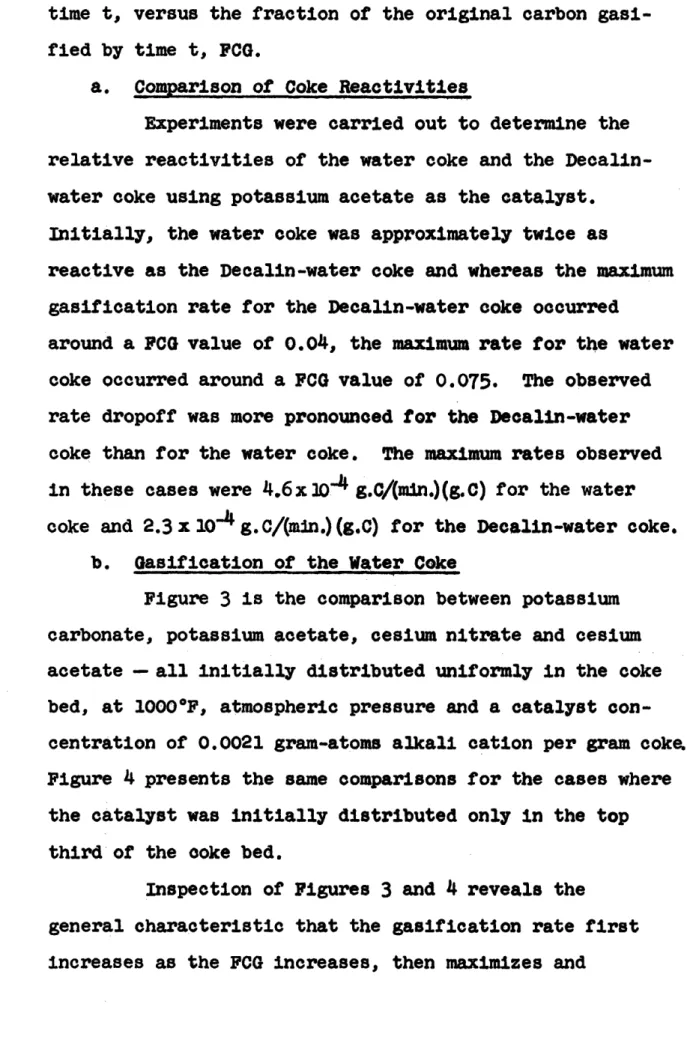
50 time t, versus the fraction of the original carbon gasi-fied by time t, FCG.
a. Comparison of Coke Reactivities
Experiments were carried out to determine the relative reactivities of the water coke and the Decalin-water coke using potassium acetate as the catalyst.
Initially, the water coke was approximately twice as
reactive as the Decalin-water coke and whereas the maximum gasification rate for the Decalin-water coke occurred
around a FCG value of 0.04, the maximum rate for the water coke occurred around a FCG value of 0.075. The observed rate dropoff was more pronounced for the Decalin-water
coke than for the water coke. The maximum rates observed in these cases were 4.6x 10⁴ g.C/(min.)(g.C) for the water
coke and 2.3x10 4 g.C/(mln.)(g.C) for the Decalin-water coke.
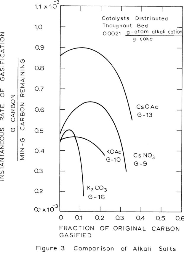
b. Gasification of the Water Coke
Figure 3 is the comparison between potassium carbonate, potassium acetate, cesium nitrate and cesium acetate - all initially distributed uniformly in the coke bed, at 10000F, atmospheric pressure and a catalyst con-centration of 0.0021 gram-atoms alkali cation per gram coke, Figure 4 presents the same comparisons for the cases where the catalyst was initially distributed only in the top third of the coke bed.
Inspection of Figures 3 and 4 reveals the
general characteristic that the gasification rate first increases as the FCG increases, then maximizes and
-3 1.1 x 1 U 1.0 0.9 0.8 0.7 0.6 0.5 0.4 0.3 0.2 103
0.1 x10
0 0.1 0.2 0.3 0.4 0.5 0.6 FRACTION GASIFIED OF ORIGINAL CARBONFigure Compar ison for Water Coke Gasif
of Alkali Salts ication at 1000 o F
-3 I.4 X IX 1.2 1.0 0.8
0.6
0.4
0.2
-3 .09 x10 0 0.1 0.2 0.3 0.4 FRACTION GASIFIED OF ORIGINAL CARBON Figure 4 Comparison Coke Gasif of Alkali Salts ication at 1000 0 Fo.5
for Water53
commences a steady decrease. The exact shape of the RI versus FCG curves varies depending on the catalyst and its initial distribution in the bed. Run G-14 (Figure 4) exhibited a different kind of behavior probably related to the initial distribution of cesium acetate.
Figure 3 illustrates clearly that cesium acetate is superior to potassium acetate as a gasification cata-lyst. The maximum gasification rate observed with cesium acetate, 8.95 x 10- 4 g.C/(min.)(g.C) occurred at a FCG
value of 0.12, while the corresponding values for the potassium acetate were 4.7 x 10- 4 g.C/(min.)(g.C) at
0.07 to 0.08, a difference of a factor of 1.9. It is also apparent from Figure 3 that at comparable levels in this experimental system, potassium acetate is superior to potassium carbonate because with the former catalyst, the gasification rate dropoff with bed burnoff is much less than with the latter catalyst. Both potassium acetate and potassium carbonate possessed virtually the same initial and maximum rates.