READ THESE TERMS AND CONDITIONS CAREFULLY BEFORE USING THIS WEBSITE. https://nrc-publications.canada.ca/eng/copyright
Vous avez des questions? Nous pouvons vous aider. Pour communiquer directement avec un auteur, consultez la
première page de la revue dans laquelle son article a été publié afin de trouver ses coordonnées. Si vous n’arrivez pas à les repérer, communiquez avec nous à [email protected].
Questions? Contact the NRC Publications Archive team at
[email protected]. If you wish to email the authors directly, please see the first page of the publication for their contact information.
NRC Publications Archive
Archives des publications du CNRC
This publication could be one of several versions: author’s original, accepted manuscript or the publisher’s version. / La version de cette publication peut être l’une des suivantes : la version prépublication de l’auteur, la version acceptée du manuscrit ou la version de l’éditeur.
Access and use of this website and the material on it are subject to the Terms and Conditions set forth at
Integration of a Tracking Laser Range Camera with the
Photogrammetry based Space Vision System
Blais, François; Beraldin, Jean-Angelo; Cournoyer, Luc; Christie, I.; Serafini,
R.; Mason, K.; McCarthy, S.; Goodall, C.
https://publications-cnrc.canada.ca/fra/droits
L’accès à ce site Web et l’utilisation de son contenu sont assujettis aux conditions présentées dans le site LISEZ CES CONDITIONS ATTENTIVEMENT AVANT D’UTILISER CE SITE WEB.
NRC Publications Record / Notice d'Archives des publications de CNRC:
https://nrc-publications.canada.ca/eng/view/object/?id=a850627e-ae63-417c-b0e7-d197bd01a1d6 https://publications-cnrc.canada.ca/fra/voir/objet/?id=a850627e-ae63-417c-b0e7-d197bd01a1d6
National Research Council Canada Institute for Information Technology Conseil national de recherches Canada Institut de Technologie de l’information
Integration of a Tracking Laser Range Camera with
the Photogrammetry based Space Vision System
F. Blais, J.-A. Beraldin, L. Cournoyer, I. Christie, R. Serafini,
K. Mason, S. McCarthy, and C. Goodall
April 2000
Copyright 2001 by
National Research Council of Canada
Permission is granted to quote short excerpts and to reproduce figures and tables from this report, provided that the source of such material is fully acknowledged.
*
published in SPIE Proceedings, AeroSense, Orlando, FL. April 24-28, 2000.In Acquisition, Tracking, and Pointing XIV, Proceedings of SPIE’s Aerosense 2000 Vol. 4025, 24-28 April 2000, Orlando, FL.
Integration of a Tracking Laser Range Camera with the
Photogrammetry based Space Vision System
*F. Blais, J.A.Beraldin, L. Cournoyer
National Research Council of Canada
Institute for Information Technology
Ottawa, Ontario, Canada, K1A-0R6
[email protected]
I. Christie, R. Serafini, K. Mason, S. McCarthy, C. Goodall
Neptec Design Group
Ottawa, Ontario, Canada
ABSTRACT
This paper presents the most up-to date experimental results obtained during the integration of a 3-D Laser Scanner Tracking System and the current Space Vision System used by NASA. Half scale models of modules of the Space Station Freedom have been built for this demonstration and comparison between the current method using video cameras and the Laser Scanner System are presented. The variable resolution laser scanner can track, in real time, targets and geometrical features of an object. The Laser Scanner System uses two high-speed galvanometers and a collimated laser beam to address individual targets on the object. Very high-resolution images and excellent tracking accuracy are obtained using Lissajous figures that provide high pointing accuracy of a laser beam. The prototype automatically searches and tracks, in 3-D, targets attached to the object. The locations of the centroid of the detected targets are fed directly into the existing photosolution and attitude control modules of the Space Vision System (SVS).
Keywords: Laser scanner, 3D, ranging, tracking, Lissajous.
1. INTRODUCTION
Experience gained in ground simulation and on orbit during space shuttle missions has proved the importance of vision for space applications. A fundamental component of the Mobile Servicing System, the Canadian contribution to the International Space Station for the automation of space-related activities, is the Artificial Vision Unit (AVU). This system will play a major role in both space station assembly and space station maintenance operations. A key component, currently used by NASA for the assembly of the Space Station Freedom is the Space Vision System developed by Neptec Design Group of Kanata, Canada. This vision system uses video cameras and photogrammetry-based methods to compute in real time the pose, position, and orientation of an object [1,2].
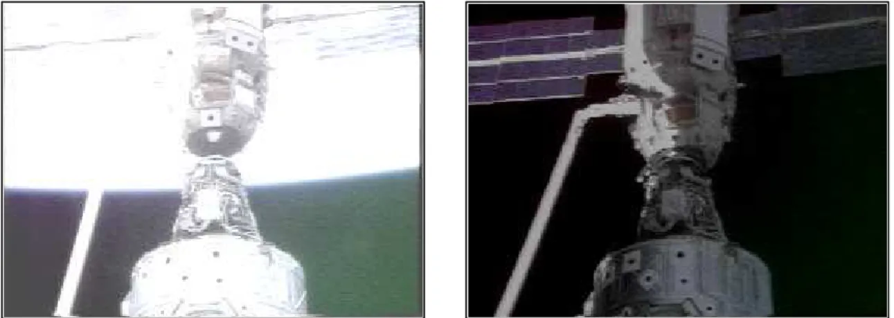
Video camera based systems are attractive because of their ease of use, low maintenance, and simplicity of integration to existing equipment. Unfortunately, the presence of the sun or any other strong sources of light adversely affect the quality of the video images. Poor contrast between features on the object and background and sharp gradients in lighting often make the images difficult to analyze. Figure 1 shows examples of video images obtained on orbit and illustrates potential problems a
*
vision system will encounter during normal operation in orbit. It is therefore highly desirable to offer a complementary vision system to general-purpose video cameras that will not be restricted by operational conditions such as sun interference, saturation, shadows, or simply insufficient light.
A laser scanner approach offers the advantage of being close to 100% operational throughout the changing illumination conditions in orbit. The technique developed at the National Research Council of Canada is designed to minimize the sensitivity of the vision system to background illumination such as the earth albedo, the sun [3], and most of its reflections. A variable resolution laser scanner that tracks, in real time, targets and geometrical features of an object has been developed for this application. The prototype automatically searches and tracks, in 3-D, targets attached to the object.
Figure 1: Examples of the effect of sun illumination and earth albedo on video image cameras: 1) light saturation, and 2) lighting gradients. The Space Vision System uses the known location of the B/W targets to compute the pose of the object(s).
Illumination conditions
Possible effect on laser scanner
Normal conditions None – normal conditions
Partial target shadowing None – outside instantaneous field of view of camera Full target shadowing Reduced accuracy – Distortion on signal or saturation Saturation (Field of view) Minimal – normally outside instantaneous FOV of camera No Light (Dark) None - Ideal for laser scanner
Estimated percentage of "conditions" of operation in orbit
60% Normal conditions 35% Shadow conditions
<5% Saturation & No Illumination <1% Back illumination
Table 2: Conditions for ambient illumination and their effect on the Laser Scanner System. Note that lighting conditions on orbit are highly dynamic and in a typical assembly operation it is not uncommon to experience the entire range of lighting conditions listed in the table.
For the Laser Scanner, to operate properly under severe ambient illumination conditions in orbit, two main technical aspects must be verified:
• Saturation of the CCD signal
The Laser Camera System demonstration project presented in this paper has two main objectives:
• To demonstrate that the Space Vision System (SVS) accuracy performance, with the Laser Camera System (LCS) used as a sensor, is equivalent to the performance of the system using a commercial or orbiter video camera as a sensor.
• To demonstrate that the LCS provides greater robustness to adverse lighting conditions than is provided by a video camera.
The laser scanner principle of operation is first explained with emphasis on the tracking method that utilizes Lissajous scanning patterns for speed, and range information to validate measurements. Then experimental comparison between the use of the LCS and the more classic video camera is shown. Finally, immunity to sun and shadow conditions such as illustrated in Figure 1 are demonstrated.
2. LASER SCANNER AND TRACKING STRATEGY
Figure 2 shows a photograph of the auto-synchronized laser scanner prototype used for this demonstration. The laser scanner uses a variation of the auto-synchronized triangulation range sensor [4,5] based on galvanometers. The system comprises two orthogonal mounted scanning mirrors, a linear CCD photosensitive position device used for short to medium range measurement, an optional photo-avalanche diode based Time-of-Flight ranging module. The TOF mode is usually used for longer-range measurements (>10-20 m; >30-60 ft) and was therefore removed for this demonstration. Laser illumination is provided using a mono-mode fiber coupled laser source, either pulsed or CW. The laser scanner operates at an eye safe wavelength of 1.5 µm.
The basic concept of auto-synchronization is that the projection of the light spot is synchronized with its detection. The instantaneous field of view of the position sensor follows the spot as it scans the scene. Therefore, an external optical perturbation can potentially interfere with the detection only when it intercepts the instantaneous field of view of the scanner. At this level, electronic signal processing is used to filter these false readings to obtain correct 3-D measurement [6]. With synchronization, the total field of view of the scanner is related only to the scanning angles of the galvanometers and mirrors as opposed to a conventional camera where field of view and image resolution are intimately linked.
Real-time tracking of targets
Because of the inertia and therefore limited speed of galvanometers, a 3-D laser scanner used in the conventional raster-imaging mode of operation will be much slower than their video camera counterparts. As shown in Figure 3, raster raster-imaging consists of scanning the scene line by line, emulating the video reading mechanism of conventional CCD/CMOS cameras. Although video 3-D range imaging has been demonstrated [7] using very fast rotating mirrors, maximum range and accuracy measurements are still very limited and far from being sufficient for this application. Table 1 illustrates the speed of acquiring a dense 3D-range image assuming an acquisition speed of 20000 Voxels/sec. It is clear that refresh rates will be prohibitively slow.
Real-time tracking of targets or geometrical features on an object is implemented using Lissajous figures, to obtain good scanning speed and accuracy. Driving the two axis galvanometers with sine waves of different frequency creates a Lissajous pattern [8]. Figure 4 illustrates the geometrical tracking principle using the 3-D range information on the Lissajous pattern, to (a) identify targets on the object or any useful geometrical feature and (b) to discriminate the target from its background as illustrated by the bounding box in Figure 4. Lissajous patterns are used to efficiently scan objects at refresh rates exceeding the bandwidth of the mechanical deflection system. The natural inertia of the galvanometer-mirror structures smoothes the scanning pattern and hence increases the pointing accuracy of the tracking system.
Figure 5 illustrates the principle associated with position tracking of a single target using a 3:2 Lissajous pattern [8]. Range and intensity data are measured for each of the N points on the scanning pattern. As mentioned previously, range and intensity data are used to discriminate target and background. The targets that have been used in this experiment were
retro-reflective enhancing the signal-to-noise ratio for the detection process. Work is underway to track the existing space qualified Inconel black-and-white targets.
Raster Mode (3-D Image Size)
Maximum Refresh Rate (sec)
128 × 128 0.8
256 × 256 3.3
512 ×512 13.1
Tracking mode Maximum Tracking Speed
Single target 6.6 msec
Multiple targets 10 msec × Targets
Table 1: Typical acquisition time for the 3-D Laser Scanner System used in raster and tracking modes, acquisition speed
is 20000 Voxels/sec1. Figure 2: Prototype of the 3-D Laser Scanner System
Figure 3: Conventional raster type imaging mode. The whole object is scanned line by line and a raster type image is created.
Figure 4: Illustration of real-time tracking of geometrical features using Lissajous pattern. Range information is used to discriminate between the object and its background.
Figure 6 shows the multiple targets tracking process in action where the laser scanner is programmed to sequentially scan different sections of the object. One of the targets is here in the search mode and the scanner uses a larger Lissajous pattern to localize it. When found, the scanner automatically switches from the search mode to the track mode using a smaller Lissajous pattern to increase target centroid accuracy. Errors introduced by the measurement process are always optimal because the scanner automatically centers and optimizes the size of the tracking patterns based on the measured target to object distance, for each target individually. The laser scanner sequentially scan different sections or targets on one or multiple objects.
1
Assuming returned laser power is sufficient, (e.g. retro-reflective targets) Object Laser Scanner Raster Scan Pattern Laser Lissajous Tracking Patterns Laser Scanner Object Laser Range Validation
The locations of the centroid of the detected targets is fed directly into the existing photosolution and attitude control modules of the current Space Vision System (SVS) that uses real-time photogrammetry techniques to compute either the absolute or relative poses (position and orientation) of multiple objects.
Figure 5: Principle of tracking using the Lissajous pattern and a circular target.
Figure 6: Real-time tracking of targets on the Node and Z1 modules used during the experimentation. Two types of target are visible, Inconel B/W and retro-reflective targets. The system tracks each target sequentially. In this example, one of the targets is in “search mode” (larger Lissajous pattern).
3. EXPERIMENTAL DEMONSTRATION
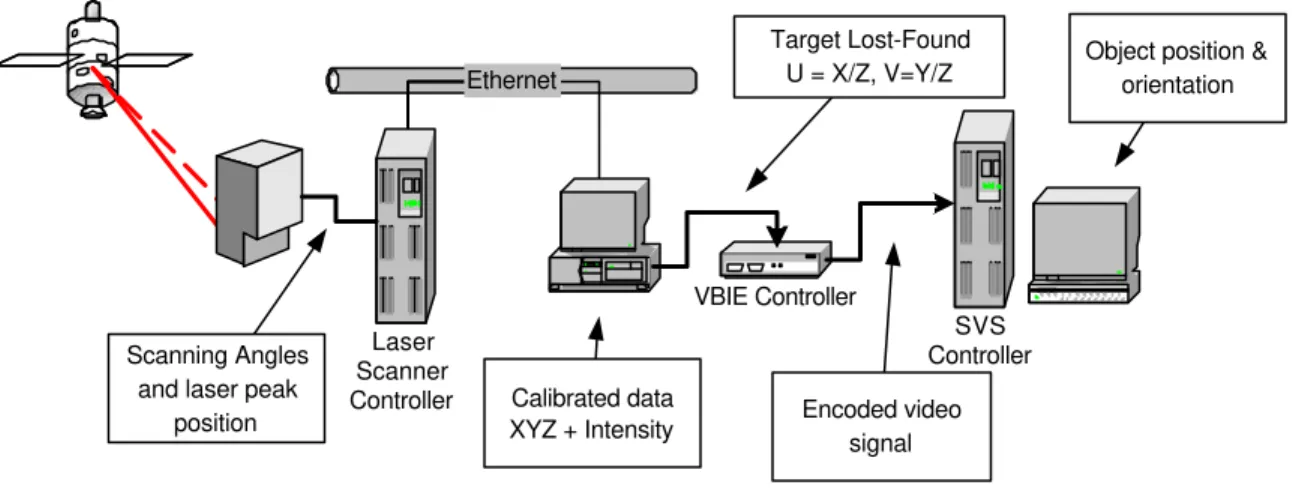
In order to demonstrate these capabilities, the Laser Camera System was interfaced with the Space Vision System by encoding the target centroid data for the targets being tracked on the Vertical Blanking Interval of the NTSC camera video. Figure 7 shows the communication structure and the data conversion applied to the LCS three-dimensional XYZ targets centroids to be compatible with the Space Vision System video format (camera view angles UV). For the SVS system, the Laser Scanner appears like a conventional video camera. A distortion free pinhole camera model is used by the SVS system because the laser scanner software model provides calibrated range data.
The encoded data consists of a flag indicating whether or not the target is valid, the number of the target (in the order that SVS is expecting), and the horizontal and vertical position of the target centroid in the laser’s image plane. Modification to the system software also included modification to the different SVS and LCS databases, laser scanner control mechanism, and calibration methods.
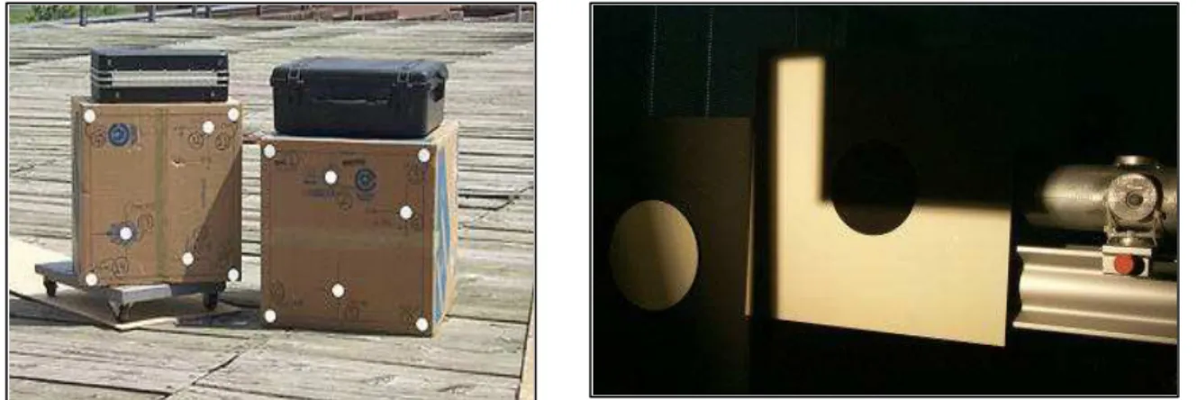
The LCS demonstration setup utilizes the 3A-Z1-install task simulation in the Neptec Vision System Certification Lab (VSCL), shown in Figure 8. This simulation consists of half-scale models of the Unity and Z1 truss models with Inconel targets applied in flight locations and closely located retro-reflective targets. The model set-up simulates an orbiter orientation with the starboard wing into the floor of the lab with the nose toward the east wall and the payload bay toward the north wall.
For demonstration purposes a good quality JVC video camera and LCS have been setup in a location that roughly approximates the center of the payload bay on a GAS bridge in the aft section of the payload bay. The LCS and camera have been left in the lab orientation, meaning that they are rolled 90 degrees in the orbiter frame of reference. This configuration is
Center of target Tracking Error Target Lissajous Scan
sufficient to demonstrate LCS performance in a flight like task geometry; the relationship between sensor, targets and payloads is representative of on-orbit operations.
Range between the Node and Camera varies between 9 m and 11 m (30-36 ft) depending on the target, and between 5 m and 8 m (16-27 ft) for the Z1 module.
The demonstration task is performed in two steps. First the Z1 model is moved away from the Node model and the Node target array is acquired. A solution is generated by SVS and the solution is stored as a reference vector. Next, the Z1 model is moved to the pre-install position, approximately 1 m from the installed position, and attached to a motorized controller stage. At this point the Z1 targets are acquired and SVS begins generating a relative solution by comparing the measured Z1 position to the stored node solution. The Z1 is then moved to the install position using the motion controller. When the SVS solution indicates that the Z1 is at the install position its location and orientation are verified. This procedure is identical for both the camera and the LCS.
Figure 7: Structure and data flow of the Laser Scanner System and Space Vision System demonstration. Communication between the LCS and SVS systems is implemented using the Video Blanking Interval Encoder (VBIE) controller.
Figure 8: The Node and Z1 modules experimental setup (1/2 scale). Ethernet Laser Scanner Controller SVS Controller VBIE Controller Scanning Angles and laser peak
position Calibrated data XYZ + Intensity Target Lost-Found U = X/Z, V=Y/Z Encoded video signal
Object position & orientation
4. EXPERIMENTAL RESULTS
The results obtained to date deal with three main areas:
• Stability and consistency of the LCS solution.
• Comparison of the LCS solution to the camera solution.
• Lighting robustness testing.
To demonstrate the full potential of the system, it is important to place these results in context and to understand the technological limitations of this first demonstration:
• The LCS uses an old galvanometer design, based on the older G325 series of galvanometers from General Scanning, which is not as precise as technology currently available. These older galvanometers are more susceptible to thermal drift than galvanometers currently available.
• This demonstration represents the first attempt at calibration of large volume. The technique is still in development. It is expected that it can be improved significantly.
Stability Tests
The problem of the thermal instability of the galvanometers is partially mitigated by the use of the relative solution mode of SVS. Provided the changes in solution produced by temperature drift are the same for both arrays, the final solution will not be affected. Therefore, prior to performing the demonstration it is critical to show that, if there is temperature drift, it is the same for all targets across the field of view of the scanner. Drift that varies from array to array will be referred to as differential drift.
The Z1 install task does not lend itself easily to repeated measurements because the Z1 obscures the targets on the node when in the “mated” position. Thus the Z1 model must be moved back to a “pre-installation” between tests in order to acquire the node targets. Therefore the differential drift stability measurements were not performed between the node and the Z1. Instead multiple arrays were defined from the targets on the Node model and the differential drift between these solutions was assessed. The arrays were all defined to have the same target point of origin so that the LCS solution for each array should be the same.
The results indicate that while there is some variation in the solution between the arrays, the differential drift is minimal. The worst case differential drift is less than 4 mm (0.15") for the entire time period.
Accuracy measurements
The second portion of testing was designed to show that these consistent results could also be translated into good and consistent agreement between the LCS and Camera solutions for the Z1 install task.
The main factor affecting the LCS to camera comparison is the calibration of the LCS. Because the two scanning axes of the LCS have different focal points there is significant astigmatism in the LCS field of view when compared to a standard video camera. This astigmatism becomes increasingly important as the volume of the scan is increased. Well-established techniques exist to perform the calibration on small volume [10]; for large volume this technique is relatively new.
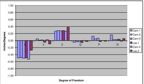
It was discovered during testing that the current calibration technique is adequate for demonstration purposes provided it is "tuned" for the specific array configuration in use. For example, Figure 9 shows a series of measurements made with the camera and LCS (with a suitably modified calibration). The results indicate that, under the correctly chosen conditions, the agreement between the camera and LCS solution is within 6 mm (0.25") and 0.25 degrees (worst case).
Figure 9: Comparison between the video camera and the LCS measurements
Lighting Robustness Testing
To demonstrate the robustness of the LCS to adverse lighting conditions, different specific lighting configurations were used. In the first configuration a light was placed so that the forward face of the Z1 model cast a sharp shadow in the vicinity of the first target in the Z1 array. By raising and lowering the light the shadow could be made to move across the face of the target such as illustrated in Figure 11. Testing showed that when using the video camera, the SVS would not continue to generate a solution when the shadow crossed the black area of the target. Once the shadow completed the transit of the target area, the solution could be resumed. When the same test was performed with the LCS there was no loss of solution. In fact, the solution did not change throughout the entire shadow transition.
The second test of lighting robustness involved shining a very directional 1000-Watt light source directly at the LCS and camera. This situation was intended to simulate the condition of the sun shining directly into the camera. The light source used is not strong enough to be considered a true simulation of the sun, it is sufficient to saturate the video camera and prevent discrimination of the SVS targets. With this light turned on, the SVS was not able to generate a solution using the video camera. Using the LCS, the SVS was able to generate a solution. There was no change in the solution when the light was turned on and off.
Figure 10: Demonstration of lighting robustness of the laser scanner under direct illumination. The video camera was moved in order to be able to take this picture and the light source is directed exactly toward the laser scanner.
-1.00 -0.80 -0.60 -0.40 -0.20 0.00 0.20 0.40 0.60 0.80 1.00 X Y Z Q P R Degree of Freedom Inches/Degrees Cam 1 Cam 2 Cam 3 Las 1 Cam 4 Las 2
The third series of measurements were done outside under clear sunny day. Different conditions of shadows and direct sun illumination were tested (e.g. early morning, using mirrors). In these later tests the pointing accuracy of individual targets were analyzed; no change in target pointing were noticeable.
Figure 11: Demonstration under direct sunlight illumination and analysis of worst case scenarios of on-orbits light conditions by removing the optical interference filter inside the laser scanner head.
Although these last tests are physically as close as possible of worst case scenarios we can obtain on earth, it can be argued that the conditions in orbit will be different because of the effect of atmospheric attenuation, especially at a wavelength of 1.5
µm. For the last series of tests, we removed the optical interference filter that is normally used in operation and utilized the full spectral bandwidth of the photo-detector. Knowing the equivalent attenuation of the optical filter, extrapolated conditions of light that will be encountered in orbit are then easily tested using less powerful light sources and a good error margin can be added. The effects of light interference are minimal when using retro-reflective targets. We are still investigating these effects with Inconel Black and White targets but preliminary results are extremely positives.
5. CONCLUSION
The LCS and SVS have been successfully interfaced and the combined system has been integrated into the half scale simulation of the 3A-Z1-installation task. Stability and accuracy measurements have been performed. The results of this testing indicate that a repeatable and accurate demonstration can be performed with the current set up, with accuracy in the order of 2.5 mm (0.1 inch) in position and 0.2 degrees in rotation, at average distances of 8.5 m (28 feet) from the camera. And the fact that the system does not use the latest in term of available technology demonstrates that even better performances can be obtained.
Lighting robustness testing has also been performed which shows that the LCS is immune to at least two classes of lighting conditions that prevent the current video camera system from operating correctly. Separate tests with direct sunlight illumination were successfully performed using retro-reflective targets.
The demonstration project has revealed that there are a number of areas that must be investigated more thoroughly for a flight test unit of the LCS to be built. These areas include investigation of flight target solutions. The demonstration task uses targets fabricated from commercial retro-reflective tape. These targets are not a flight quality solution. There is also a compelling argument for attempting to use the LCS with the existing inconel targets. We have done some initial feasibility work in this area but a more complete investigation is needed to determine if the existing inconel B/W targets are an operationally viable option.
6. REFERENCES
1. S.G. MacLean, and H.F.L. Pinkney, ``Machine Vision in Space,” Canadian Aeronautics and Space Journal, 39(2), 63-77 (1993).
2. S.G. MacLean, M. Rioux, F. Blais, J. Grodski, P. Milgram, H.F.L. Pinkney, and B.A. Aikenhead, “Vision System Development in a Space Simulation Laboratory,”in Close-Range Photogrammetry Meets Machine Vision, Proc. Soc. Photo-Opt. Instrum. Eng., 1394, 8-15 (1990).
3. G.H. Suits, “Natural Sources,”Chap.3 in The Infrared Handbook by W.L.Wolfe and G.J. Zissis Editors, ERIM, 1989. 4. F. Blais, M. Rioux, and J.-A. Beraldin,”Practical Considerations for a Design of a High Precision 3-D Laser Scanner
System,” Proc. Soc. Photo-Opt. Instrum. Eng. 959, 225-246 (1988).
5. M. Rioux, “Laser Range Finder based on Synchronized Scanners,”Appl. Opt., 23, 3837-3844 (1984).
6. F. Blais, J.-A. Beraldin, M. Rioux, R.A. Couvillon, and S.G. MacLean, “Development of a Real-time Tracking Laser Range Scanner for Space Application,” Proceedings Workshop on Computer Vision for Space Applications, Antibes, France, September 22-24, 161-171 (1993).
7. F.R. Livingstone, L. King, J.-A. Beraldin, and M. Rioux, ”Development of a Real-Time Laser Scanner System for Object Recognition, Inspection, and Robot Control,” Proc. Soc. Photo-Opt. Instrum. Eng., 2057, 454-461 (1993). 8. F. Blais, M. Rioux, and S.G. MacLean, “Intelligent, Variable Resolution Laser Scanner for the Space Vision System,” in
Acquisition, Tracking, and Pointing V, Proc. Soc. Photo-Opt. Instrum. Eng., 1482, 473-479 (1991).
9. D.G. Laurin, F. Blais, J.-A. Beraldin, and L. Cournoyer, “An eye-safe Imaging and Tracking laser scanner system for space Applications,” Proc. Soc. Photo-Opt. Instrum. Eng. 2748, 168-177 (1996).
10. J.-A. Beraldin, S.F. El-Hakim, and L. Cournoyer, “Practical Range Camera Calibration,” Proc. Soc. Photo-Opt. Instrum. Eng. 2067, 21-31 (1993).