HAL Id: hal-01875447
https://hal.laas.fr/hal-01875447
Submitted on 17 Sep 2018
HAL is a multi-disciplinary open access
archive for the deposit and dissemination of
sci-entific research documents, whether they are
pub-lished or not. The documents may come from
teaching and research institutions in France or
abroad, or from public or private research centers.
L’archive ouverte pluridisciplinaire HAL, est
destinée au dépôt et à la diffusion de documents
scientifiques de niveau recherche, publiés ou non,
émanant des établissements d’enseignement et de
recherche français ou étrangers, des laboratoires
publics ou privés.
Céline Leclerc, Maxime Romier, Hervé Aubert, Ayoub Annabi
To cite this version:
Céline Leclerc, Maxime Romier, Hervé Aubert, Ayoub Annabi.
Ka-Band Multiple Feed per
Beam Focal Array Using Interleaved Couplers.
IEEE Transactions on Microwave Theory
and Techniques, Institute of Electrical and Electronics Engineers, 2014, 62 (6), pp.1322-1329.
�10.1109/TMTT.2014.2320697�. �hal-01875447�
Abstract— In this paper, an original focal array for multibeam
antenna is presented. It is based on Multiple Feed per Beam geometry. Each beam is produced by a cluster of feed horns illuminating a parabolic reflector. Three adjacent clusters of the focal array overlap for enhancing the illumination performance within the size-constrained array lattice. The Beam-Forming Network is the key component and drives the overall performance of the radiating structure. It is composed of tri-dimensional interleaved couplers made of circular waveguides and interconnected by thin radial rectangular waveguides. The design, manufacturing and measurement of a Ka-band Multiple Feed per Beam focal array are reported. It is composed of 31 feed horns displayed in 7 clusters, for a global size of about 6λd where
λd denotes the free-space wavelength at the lowest operating
frequency. The realized gain is higher by 1dB than the gain provided by the Single Feed per Beam focal array having analogous size.
Index Terms—focal array, Multiple Feed per Beam, Single
Feed per Beam, Beam-Forming Network, directional coupler, Ka-band.
I. INTRODUCTION
ULTIBEAM antennas become more and more used on communication satellites. They allow conveying different data over different areas of a geographical coverage, via independent beams, inducing a leap of capacity in comparison with antennas radiating a single wide beam [1]. Feed arrays set in front of reflectors are commonly used to generate a multibeam coverage over a limited field of sight. The design of these antennas results from a trade-off between reflector size, feed array lattice dimensions and, radiating performances [2]. Large feeds may provide the required beam and the desired Carrier-over-Interference ratio as they allow reducing spill-over losses and Side Lobe Level. However, the feed lattice must be tight enough to fulfill the beam density
This work was supported by the French Space Agency (CNES) and COBHAM. The manufacturing of the mock-up was funded by the CNES R&T program.
C. Leclerc was with the MIcro and Nanotechnology for wireless Communication group, LAAS-CNRS, Toulouse, 31077 France until september 2013 (e-mail: [email protected])
M. Romier is with Antenna Department in RadioFrequency Group, CNES (French Space Agency), Toulouse, France.
H. Aubert is with the MIcro and Nanotechnology for wireless Communication group, LAAS-CNRS, Toulouse, 31077 France, and also with the Ecole Nationale Supérieure d’Electrotechnique, d’Electronique, d’Informatique, d’Hydraulique et des Télécommunications, 31071 Toulouse, France (e-mail: [email protected])
A. Annabi is with Antenna Department, Cobham, Dourdan, France.
requirement over the coverage.
In Single Feed per Beam (SFB) focal arrays, each beam is produced by a single feed in the reflector focal plan [2]–[5]. Feeds generally operate both in transmission and reception [6]. To achieve a very small beam-spacing with acceptable spill-over losses, feeds must be dispatched in front of typically 3 or 4 reflectors [1]. However these reflectors have large dimension and consequently, they may be difficult to accommodate on satellites. Moreover their implementation leaves little available room for other antennas addressing different services. Multiple Feed per Beam (MFB) focal arrays are good candidates for reducing the number of reflectors for similar performances [4], [7]–[9]. In MFB focal arrays, each beam is produced by a cluster of radiating elements which are fed by an appropriate Beam-Forming Network (BFN). From the overlap of adjacent clusters the radiating surface is enlarged without increasing the beam spacing. Moreover MFB focal arrays allow producing spots using a single reflector [4] and consequently, only two antennas are generally required, one for transmitting data and one for the reception. However BFN used in MFB antennas are often difficult to design and are geometrically complex with a combination of many different couplers and phase-shifters [4], [9].
An original MFB focal array architecture based on interleaved couplers has been very recently patented by one of us [10]. A very preliminary design was reported by the authors in 2012 [11] with prior results of the focal array associated with a parabolic reflector. Finally, a photography of the fabricated feed array was shown in 2013 [12] while very briefly describing the design and manufacturing process. However, the design, manufacturing and measurement (which is compared to simulation results) of such original MFB focal array are reported here with details for the first time. A special focus is devoted to the BFN based on interleaved tri-dimensional (3-D) directional couplers and a specific design is reported for fulfilling the technical requirements of a Ka-band multimedia mission. The measured return loss is less than -19.4dB between 18GHz and 20GHz while the realized gain of the designed MFB focal array is 15dBi at 18.5GHz, that is, higher than the gain (14 dBi) of a SFB focal array having similar size. Moreover only two reflectors are required for meeting transmission/reception requirements. The measurement results reported in Section III are in good agreement with the simulation results given in Section II.
The paper is organized as follows. In Section II the design of the focal array composed of interleaved 3-D directional couplers, waveguide phase-shifters and horn antennas is detailed. Full-wave electromagnetic results are reported in
Ka-Band Multiple Feed per Beam Focal Array
Using Interleaved Couplers
Céline Leclerc, Maxime Romier, Hervé Aubert, Senior Member, IEEE, and Ayoub Annabi, Member, IEEE
TABLEI
FOCAL ARRAY SPECIFICATIONS.
Tx Frequency Band 18 GHz – 20GHz Frequency Bandwidth 10% Polarization Circular RHCP/LHCP Re-use Schema 4 colors: LHCP 18.5 GHz; RHCP 18.5 GHz; LHCP 19.5 GHz; RHCP 19.5 GHz Return Loss < -22 dB Focal Array Radiating Element Spacing
P = 16.6 mm
Focal Array Cluster Spacing P√3 = 28.75 mm Focal Array Length < 250 mm
Material Aluminum
Fig. 1. Typical block diagram of a focal array.
II. DESIGN OF A KA-BAND MFBFOCAL ARRAY USING
INTERLEAVED 3-DDIRECTIONAL COUPLERS
Typical technical requirements for a Ka-band multimedia focal array are summarized in Table I. The main difficulty is to achieve return loss less than -22dB over the whole bandwidth. As sketched in Figure 1 the focal array is composed of input ports (one port per beam), a BFN and an array of radiating elements. In the MFB approach, each beam is produced by a cluster of several radiating elements. The purpose of increasing the overlapping of the clusters is to obtain, for a given cluster spacing, a better illumination of the reflector i.e. less spill-over losses and lower side lobes. The Fig. 2 illustrates the case of a MFB array using 7 feed horns and four colors frequency and polarization re-use scheme. The detail of these colors is listed in Table I where each color is a combination of one of the two possible sub-bands (18-19 GHz and 19-20 GHz, no guard-band being accounted) and of one of the two possible polarizations (RHCP and LHCP). Each peripheral radiating element of a cluster is indicated by a white disk in Fig. 2(a) and is involved in the generation of three beams. The dotted circle encloses the radiating elements that are involved in the generation of one beam. For the radiating surface of Fig. 2(a) the shortest spacing between clusters is P√3 where P is the distance between the centers of two adjacent horn antennas. This spacing (2P) is larger in case of the MFB focal array reported in [7][8] where one peripheral radiating element of a cluster is used twice, as illustrated in Fig. 2(b). In the two MFB focal arrays shown in Fig. 2 the shape of the clusters are identical but the spacing between cluster centers differs. The size of the MFB focal array proposed in this paper and shown in Fig. 2(a) is around 6λd x
6λd where λd denotes the free-space wavelength at the lowest
observed from Fig. 2(b).
Fig. 2. Front view of the focal array and the overlapped feed clusters (four color re-use scheme). Each beam is produced by a cluster composed of seven feed horns enclosed by colored dotted circle. Peripheral horns (white disks) are involved in : (a) three adjacent clusters (our approach); (b) two adjacent clusters [7] [8].
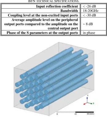
TABLEII
BFNTECHNICAL SPECIFICATIONS.
Input reflection coefficient < -26 dB Bandwidth 18-20GHz Coupling level at the non-excited input ports < -30 dB
Average amplitude level on the peripheral output ports compared to the amplitude on the central output port
~ 8 dB
Phase of the S parameters at the output ports in phase
Fig. 3. Illustration of the BFN.
The core of the focal array is the Beam-Forming Network (BFN) which must be specifically designed to achieve the required overlapping of radiating elements clusters. The technical specifications of the BFN are listed in Table II. It is composed of 3-D directional couplers to distribute the input power among the seven feed horns of the cluster and, phase-shifters to equalize the phase at the output ports (see Fig. 3). The BFN input ports may be connected to septum polarizers to produce a circularly polarized TE11-mode (waveguide septum
polarizers with circular core as reported in [13] could be used in our application but their design and measurement are out of the scope of the present paper). Each 3-D directional coupler
is composed of one circular waveguide surrounded by six identical circular waveguides. The peripheral waveguides are connected to the central one through thin radial rectangular waveguides, which form coupling slots between waveguides. The number and the size of the slots control the power distribution at the output of the coupler. The circular and rectangular waveguides are such that only the fundamental mode is propagating in the operating bandwidth. In the circular waveguide, only the TE11-mode is propagating while
in the rectangular waveguide, only the TE10-mode is
propagating. Consequently the radius R of the circular waveguide is such that [14]:
H TM L TE f c R f c π χ π χ 2 2 01 11 ⋅ ≤ ≤ ⋅ (1)
where fL and fH designate respectively the lowest and the
highest frequencies of the bandwidth, 11
TE
χ (resp., 01
TM χ ) is the first root of the first kind Bessel functions of order 1 (resp., of order 0) and, c denotes the vacuum celerity of light. Moreover the largest dimension of the rectangular waveguide cross section is such that:
a c fL
2
< (2) This restriction ensures that only the fundamental TE10-mode
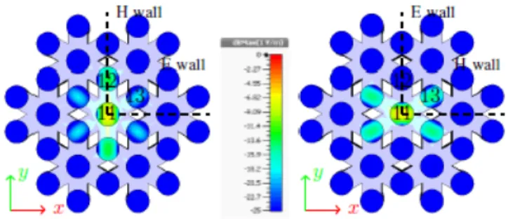
in the rectangular waveguides of width a will propagate. As illustrated in Fig. 4 the simulated structure is a directional coupler surrounded by 6 identical couplers in order to take into account the actual electromagnetic interactions between clusters. Optimizations and analyses have been performed using CST Microwave Studio 2012 [15] and the Finite Integration Technique for achieving the technical requirements of Table II. To reduce the computation time, linearly-polarized excitations (vertical and horizontal TE11
-mode excitation) have been set at the input of the structure during optimization. Perfect electric (E wall) or magnetic (H wall) boundary conditions have been inserted in the symmetry plane of the structure (see Fig. 4 for the visualization of the symmetry planes). The main properties of interleaved couplers can then be derived from the electromagnetic simulation of a quarter of the geometry (note that simulation results of the overall structure using circularly-polarized excitations have been run afterward for validation and have been found very close to the results obtained from taking advantage of the symmetries). Fig. 5 shows the amplitude of the electric field at the center of the couplers at 18.5 GHz for the vertically-polarized excitation. Fig. 6 shows the amplitude of the electric field at the output of the couplers at 18.5 GHz, for vertically (V) and horizontally (H) polarized excitations. As expected, it appears that the electromagnetic field is spread among central and peripheral waveguides. At the coupler output and for linear polarizations, a strong coupling is obtained along the axis of the input TE11 electric field (along Ox- or Oy- axis).
Some undesirable energy flows on the surrounding clusters but the amount remains lower than -25dB compared to the maximum input energy. This low value ensures the excitation
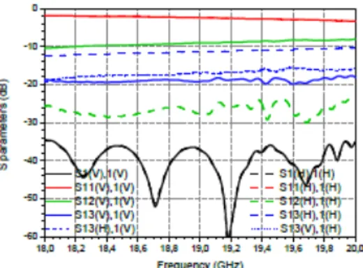
coefficient at the input of the radiating elements as most of the energy for one excited beam remains in the excited cluster. Fig. 7 shows that the simulated reflection coefficient (black curve) at the input port of the central waveguide of the BFN is less than < -34dB, as required. Moreover the amplitudes of the transmission coefficients in the peripheral waveguides are quasi-uniform over the whole bandwidth.
Fig. 4. RF modeling of seven interleaved directional couplers.
Fig. 5. E-field magnitude (f=18.5 GHz) in the plane x=0 for a vertically polarized incident TE11 on the central waveguide.
Fig. 6. E-field magnitude (f=18.5 GHz) at the output of the couplers for a vertically (on the left) and a horizontally (on the right) polarized incident TE11-mode on the central waveguide.
Fig. 8 shows the amplitude of the electric field at the output of the coupler when the central waveguide is excited by a circularly-polarized wave, that is, the superposition of two orthogonal TE11-modes with the same amplitudes but a 90°
phase-shift. The field is nearly equally distributed on the output of the peripheral waveguides. The difference between the amplitude of the electric field in the central waveguide and one in the peripheral waveguides are around 10dB, which is close to the specification defined in Table II. Fig. 9 shows the phase-shift at the output of the coupler between the central
18.5 GHz and consequently, phase-shifters must be used for obtaining in-phase electric fields at the output ports. The waveguide phase-shifters are composed of a cascade of circular waveguides with appropriate radii and electrical lengths (see Fig. 10), connected to peripheral waveguides. The phase-shift φ provided by the circular waveguide of length Lφ and radius Rφ is given by:
ϕ λ π ϕ L g 2 = (3)
where λg denotes the guided wavelength of the TE11-mode
given by [14]:
Fig. 7. S-parameters amplitude vs. frequency for a coupler surrounded by six other couplers, fed by a vertical (V) or horizontal (H) TE11-mode at the input
of the central coupler (the port numbering is shown on fig 6: return loss S1(V or H),1(V or H) and transmission coefficients S11(V or H),1(V or H); S12(V or H),1(V or H); S13(V or H),1(V); S13(H or V),1(H)).
Fig. 8. E-field magnitude (f=18.5 GHz) at the input (on the left) and at the output (on the right) of the couplers for a circularly polarized incident wave on the central waveguide.
Fig. 9. Phase difference vs. frequency between the central (port #11) and the peripheral outputs (ports #12, #13 with a vertical TE11-mode, and #13 with a
horizontal TE11-mode) of the coupler for a vertically-polarized excitation.
Fig. 10. Longitudinal view of the phase-shifter stage composed of a straight circular waveguide for the central output (top) and stepped circular waveguide with various radii for peripheral outputs (bottom).
Fig. 11. Phase difference vs. frequency, between the central and the peripheral outputs of the coupler terminated by the phase-shifter stage, for a vertically-polarized excitation. 2 0 0 1 − = c g λ λ λ λ (4)
with λ0=c/f is the free-space wavelength at the central
operating frequency and λc the cut-off frequency of the TE11
-mode. This wavelength is given as follows: 11 2 TE c R χ π λ = ϕ (5)
The phase-shifter is finally composed of 3 stages, the first one being the input waveguide and, the third one the output waveguide (see Fig. 10). Fig. 11 shows the simulated residual phase-shift when connecting the designed phase-shifters at the output of the coupler. Acceptable phase compensation is then obtained over the complete bandwidth.
As sketched in Fig. 1 the phase-shifter stage is loaded by an array of radiating elements. Radiating elements are here two-steps circular horns (see Fig. 12). The geometry of the two-steps was optimized to minimize input reflection coefficient and maximize the directivity. Fig. 13 shows the simulated return loss at the input of the single horn antenna, which remains below -28.5 dB over the frequency band. This result holds also for a feed horn surrounded by six other matched feed horns (the return loss exceeds 28dB). The simulated directivity of
the horn when surrounded by the other horns reaches 10.7 dBi at 18.5 GHz.
Fig. 12. Longitudinal view of the two-steps circular horn – R1a = 5.75 mm, L0
= 1 mm.
Fig. 13. Return loss of the two-steps circular horn, alone (plain curve) and surrounded by six other horns (dotted curve).
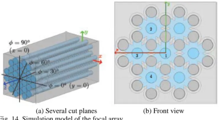
(a) Several cut planes (b) Front view Fig. 14. Simulation model of the focal array.
The designed BFN, phase-shifters and antenna array are finally cascaded in order to predict the electromagnetic performance of the resulting MFB focal array (see Fig. 14). Fig. 15 shows the return loss at the input port of the central cluster when exciting a TE11-mode. Results are identical for
both polarizations of this mode (H or V). The simulated return loss is lower than -21dB over the overall operating bandwidth. A minor non-compliance to return loss requirement (<-22dB) can be observed above 19.8 GHz, which is acceptable considering the excellent average level. Fig. 16 displays the coupling coefficient SX,1 between the port X and the port 1
(see Fig. 15(b)) between central cluster and adjacent cluster ports, when the central input port corresponding to the central cluster is excited by the vertical TE11-mode. The coupling
level is lower than -30dB over the considered bandwidth, as
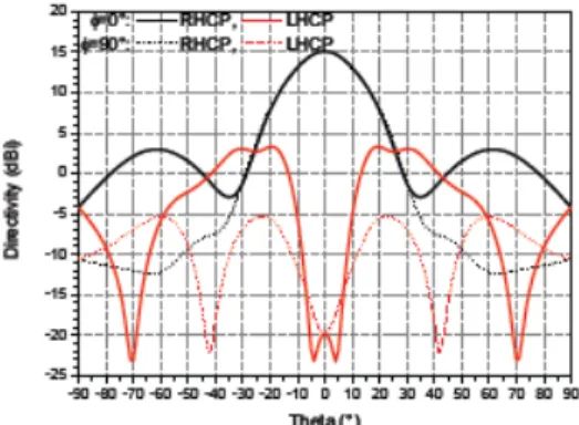
required. The simulated radiation pattern of the antenna array when feeding the central cluster by a circularly-polarized excitation is displayed in Fig. 17. A directivity of 15.1 dBi is obtained at 18.5 GHz. It is interesting to compare this result with the theoretical directivity of a SFB focal array (one reflector configuration) with similar size. In this case the SFB focal array reduces to a single feed horn with a diameter equals to the spacing d between clusters (see Fig. 18). Assuming an aperture efficiency η of 90%, the directivity D =
η 4πS/
λ
2where S=π
R
a2 denotes the surface of equivalentradiating aperture [16] is found to be 14.2 dBi. Therefore the MFB design leads to an improved directivity of around 1dB compared with a SFB focal array with an equivalent size. It must be underlined that a 1dB improvement is highly valuable for such application: it gracefully decreases spill-over loss (RF power is a precious commodity in spacecraft) and increase illumination taper (which drives C/I performance). Some undesirable cross-polarization can be observed off axis in some cut planes. However, it has been shown in prior work [11] that for typical reflector geometry, this cross-polarized lobe is not a major contributor to C/I, since it is for most part rejected out of the reflector field of view.
Fig. 15. Simulated input reflection coefficient of the MFB focal array fed by a linearly-polarized mode (vertical: S1(V),1(V); horizontal: S1(H)1(H)) .
Fig. 16. Simulated coupling coefficients of the MFB focal array fed by a linearly-polarized mode (vertical: Sx(H or V),1(V); horizontal: Sx(H or V)1(H)) .
Fig. 17. Simulated directivity of the central cluster (f=18.5 GHz) fed by a circularly-polarized excitation for several φ planes.
Fig. 18. Scheme of a SFB aperture compared to a MFB aperture with 7 horns to form 1 cluster. Ra is the radius of the RF aperture, g=0.6mm is the gap
between two adjacent RF apertures.
III. MEASURED PERFORMANCES OF THE FOCAL ARRAY
A prototype has been manufactured (see Fig. 19) by SAP Micro Mecanique©. The mock-up is made by stacking aluminum milled layers. For the couplers stage, these layers are pierced. Next they are milled only on one face to form the rectangular slots. The phase-shifters stage is also fabricated by using several metallic layers for milling the different radii. As for fabricating the horns stage, it is milled in one layer. All these layers are finally gathered together. Several metallic rods are used to ensure the alignment of the layers. Fig. 20(a) highlights the process of assembling the mock-up, beginning by the radiating elements array where fifteen rods are screwed in. Three more rods are used to reinforce the alignment. Finally, the mock-up is tied via three rods to a base which is used as mechanical interface. The feed array (without the three rods and the base) has a total length of 225 mm. A specific millimeter-wave test interface has been designed to connect the input of the focal array to the test transition. This interface gives access to the central cluster port. The transition (see Fig. 20(b), [17]) used for having an access to the linear polarization has large flanges which obstruct the other beam input ports and consequently, the peripheral clusters ports are terminated by metallic plates. In order to compare measurement data with simulation results, this interface has been added to the electromagnetic simulation model. Moreover, only one port has been inserted while the other input ports were loaded by short-circuits. The return loss and the radiation pattern have been measured in the antennas measurement facilities of the French Spatial Agency. Linearly-polarized excitations have been applied at the input of the central cluster. The measured return loss of the focal
bandwidth and higher than 25dB at 18.5GHz and 19.5GHz. A good agreement is observed between simulation and measurement results. Further measurements of the S-parameters were not performed yet due to the test transition obstructing the other clusters ports. Moreover, only one mock-up of the focal array has been fabricated. Therefore, the measurement of the transmission coefficients of the stage of couplers is not available for comparison with simulation results yet.
Fig. 19. MFB focal array mock-up (courtesy of SAP Micro Mecanique©).
(a) (b)
Fig. 20. (a) Mock-up assembly with the alignment of the milled layers (SAP Micro Mecanique©) and (b) transitions used to realize the linear excitation.
Fig. 21. Simulated and measured return loss at the input port of the central cluster of the mock-up with test transitions.
Fig. 22. Realized gain vs. frequency (experimental and simulation results) for a vertically-polarized excitation.
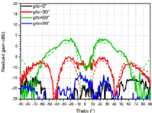
Fig. 23. Radiation pattern of the co-polarization of the realized gain at 18.5 GHz of the central cluster fed by a vertically polarized excitation, simulated (dashed lines) and measured (solid lines), for several ϕ planes.
Fig. 22 shows the variation of realized gain in the direction θ=0° versus frequency. The very good agreement between measurement and simulation data validates the design. Note that the large variation of the gain over the frequency band is mainly caused by short-circuits, imposed by the transition, set at the input of peripheral clusters. When the input ports of peripheral clusters are matched, the variation of the (simulated) gain is significantly reduced (see the dashed curve with cross markers of Fig. 22). The theoretical directivity of the SFB focal array (one reflector configuration) with similar size considered in Section II is given for comparison in Fig. 22 (with insertion loss of 0.2dB). The agreement with the simulation results is good. Depending if the beam inputs ports are impedance matched or are terminated by short-circuits, the magnitude of the gain differs and can be quite high. However, in both cases, it remains higher (+1dB) than one obtained from a SFB antenna. Several cut-planes of the measured radiation pattern (realized gain) at 18.5 GHz are displayed on Fig. 23 and Fig. 24. Again the agreement between simulation and experimental results is good. The realized gain reaches 15dBi at 18.5 GHz. As for measurement in circular polarization, a septum polarizer will be added to the focal array. However this device is not yet manufactured. Another solution would be to perform measurement in the orthogonal linear polarization and to recombine the results of the two orthogonal polarizations to access to the circular polarization. However, this solution has not been tested either yet.
Fig. 24. Radiation pattern of the cross-polarization of the realized gain at 18.5 GHz of the central cluster fed by a vertically polarized excitation, simulated (dashed lines) and measured (solid lines), for several ϕ planes.
IV. CONCLUSION
An MFB focal array architecture using interleaved couplers has been presented. Promising results in terms of performances and lattice compactness have been obtained and validated by measurement. The overlapping of feed clusters has been proved effective and the focal array is then a good candidate for reducing the number of reflectors to realize multibeam coverages on communication satellites. Moreover, if needed, the magnitude of the output electric field can be adjusted by modifying the size of coupling slots and adjusting some phase-shifters to bring the expected illumination law at the input of the antenna array. Septum polarizers will be added at clusters inputs to directly produce the circular polarization (work under way).
ACKNOWLEDGMENT
The authors wish to thanks D. Belot and L. Feat from the CNES antenna measurement laboratory for advice and measurements.
References
[1] C. Mangenot and W.A. Imbriale, “Space Antenna Challenges for Future Missions, Key Techniques and Technologies,” in Space Antenna
Handbook, W. A. Imbriale et al, Eds. Chichester, UK: John Wiley &
Sons, Ltd, 2012, ch. 18, sec. 5.
[2] K.S. Rao, “Design and analysis of multiple-beam reflector antennas,”
IEEE Antennas Propagat. Mag., vol.41, no.4, pp.53–59, Sept., 1999.
[3] P. Balling et al., “Shaped single-feed-per-beam multibeam reflector antenna,” in 1st European Conf. Antennas and Propagation (EuCAP), Nice, 2006, pp. 1–6.
[4] M. Schneider et al., “Antennas for multiple spot beam satellites”,
Council of European Aerospace Societies (CEAS) Space Journal, vol.2,
pp. 59–66, Aug., 2011.
[5] P. Lepeltier et al., “Recent achievements and future trends for multiple beam telecommunication antennas,” in 15th Int. Symp. ANtenna
Technology and applied ElectroMagnetics (ANTEM), Toulouse, 2012,
pp. 1–6.
[6] D. Scouarnec et al., “Current antenna products and future evolution trends for telecommunication satellites application,” in 3rd IEEE-APS
Topical Conf. Antennas and Propagation in Wireless Communications (APWC), Torino, 2013, pp. 1412–1415.
[7] R. Gehring et al., “Trade-off for overlapping feed array configurations,” in 29th ESA Antenna Workshop Multiple Beams and Reconfigurable
Antennas, Noordwijk, 2007.
[8] E. Reiche et al., “Space fed arrays for overlapping feed apertures,” in
Berlin, 2009, pp. 726–729.
[10] M. Romier, “Multibeam Source,” World Patent WO 2013 050517, April 11, 2013.
[11] C. Leclerc et al., “Design of multiple feed per beam antenna based on a 3-D directional coupler topology,” in 15th Int. Symp. ANtenna
Technology and applied ElectroMagnetics (ANTEM), Toulouse, 2012,
pp. 1–5.
[12] C. Leclerc et al., “Ka-band Multiple Feed per Beam antenna architecture based on interleaved 3-D directional couplers,” in 3rd IEEE-APS
Topical Conf. Antennas and Propagation in Wireless Communications (APWC), Torino, 2013, pp.367–369.
[13] R. Behe and P. Brachat, “Compact duplexer-polarizer with semicircular waveguide [antenna feed],” IEEE Trans. Antennas Propag., vol.39, no.8, pp.1222–1224, Aug., 1991.
[14] R.E. Collin, “Waveguides and Cavities,” in Field Theory of Guided
Waves, 2nd ed. Piscataway, NJ: IEEE Press, 1991, ch. 5.
[15] CST Microwave Studio
http://www.cst.com/Content/Products/MWS/Overview.aspx
[16] C.A. Balanis, “Aperture antennas,” in Antenna Theory: Analysis and
Design, 2nd ed. New York:John Wiley & Sons, Inc., 1997, ch. 12.
[17] http://www.flann.com/Products Home/Transition Polarisers /transition polarisers.html