Publisher’s version / Version de l'éditeur:
PHOENICS Journal : Computational Fluid Dynamics & its Applications, 14, June 1, pp. 1-11, 2001-06-01
READ THESE TERMS AND CONDITIONS CAREFULLY BEFORE USING THIS WEBSITE.
https://nrc-publications.canada.ca/eng/copyright
Vous avez des questions? Nous pouvons vous aider. Pour communiquer directement avec un auteur, consultez la
première page de la revue dans laquelle son article a été publié afin de trouver ses coordonnées. Si vous n’arrivez pas à les repérer, communiquez avec nous à [email protected].
Questions? Contact the NRC Publications Archive team at
[email protected]. If you wish to email the authors directly, please see the first page of the publication for their contact information.
NRC Publications Archive
Archives des publications du CNRC
This publication could be one of several versions: author’s original, accepted manuscript or the publisher’s version. / La version de cette publication peut être l’une des suivantes : la version prépublication de l’auteur, la version acceptée du manuscrit ou la version de l’éditeur.
Access and use of this website and the material on it are subject to the Terms and Conditions set forth at
Calculations of thermal and electrical distributions in silicon
microstructures
Beale, S. B.; Djebbar, R.; Post, M.
https://publications-cnrc.canada.ca/fra/droits
L’accès à ce site Web et l’utilisation de son contenu sont assujettis aux conditions présentées dans le site LISEZ CES CONDITIONS ATTENTIVEMENT AVANT D’UTILISER CE SITE WEB.
NRC Publications Record / Notice d'Archives des publications de CNRC: https://nrc-publications.canada.ca/eng/view/object/?id=a22e62a6-3afa-4f36-b650-2a0fa0ddad37 https://publications-cnrc.canada.ca/fra/voir/objet/?id=a22e62a6-3afa-4f36-b650-2a0fa0ddad37
http://www.nrc-cnrc.gc.ca/irc
Ca lc ula t ions of t he rm a l a nd e le c t ric a l dist ribut ions in silic on
m ic rost ruc t ure s
N R C C - 4 4 7 6 6
B e a l e , S . B . ; D j e b b a r , R . ; P o s t , M .
J u n e 2 0 0 1
A version of this document is published in / Une version de ce document se trouve dans:
PHOENICS Journal : Computational Fluid Dynamics & its Applications,
14,
(1), June, pp. 1-11, June 01, 2001
The material in this document is covered by the provisions of the Copyright Act, by Canadian laws, policies, regulations and international agreements. Such provisions serve to identify the information source and, in specific instances, to prohibit reproduction of materials without written permission. For more information visit http://laws.justice.gc.ca/en/showtdm/cs/C-42
Les renseignements dans ce document sont protégés par la Loi sur le droit d'auteur, par les lois, les politiques et les règlements du Canada et des accords internationaux. Ces dispositions permettent d'identifier la source de l'information et, dans certains cas, d'interdire la copie de documents sans permission écrite. Pour obtenir de plus amples renseignements : http://lois.justice.gc.ca/fr/showtdm/cs/C-42
CALCULATIONS OF THERMAL AND ELECTRICAL DISTRIBUTIONS
IN SILICON MICROSTRUCTURES
S.B. BealeR.Djebbar M.L. Post
National Research Council, Montreal Road, Ottawa, Ontario Canada
S.V. Zhubrin
Concentration Heat and Momentwn Ltd, London, U.K.
May 2000
This work was conducted using PHOENICS version3.2on Silicon Graphics workstations operating under IRlX, and on Pentium PC's operating under MSWindowsNT
Abstract:
This paper describes a research programme directed towards modelling the thermo-mechanical behaviour of silicon microstructures. A three-dimensional numerical scheme was used to compute heat transfer and distribution of electric potential in the layers of two microhotplate designs. Detailed information were obtained on the local temperature distribution in the designs, and surrounding substrate. Variable properties of the different layers in the microstructures were accounted for. Calculations indicated that overall heat transfer coefficients obtained from these studies agreed with values derived from experimentally obtained emission data, to within 6%.
TABLE OF CONTENTS
INTRODUCTION
MATIlEMATICALDETAlLS
PHOENICSSETTINGS
EXPERIMENTAL WORK
PRESENTATION AND DISCUSSION OF RESULTS
LOCAL TEMPERATURE DISTRIBUTION
PHYSICAL REALISM AND NUMERICAL ACCURACY CONVERGENCE AND GRID INDEPENDENCE
COMPUlER STORAGE AND TIME
SIGNIFICANCE IN RELATiON TO OBJECTIVE OF WORK
CONCLUSIONS RECOMMENDATIONS ACKNOWLEDGEMENT LITERATURE REFERENCES NOMENCLATURE
-2-Introduction
Production and use of microelectromechanical systems (MEMS) have increased dramatically in recent years. Consequently, the design of such systems has assumed a prominent role in science and technology; for a recent review of thermophysical engineering of MEMS, see [1]. As a result of decreases in design-cycle times and costs; increased reliance is now being made upon the use of computer software complemented with appropriate empirical data, in the design of MEMS. This paper describes an ongoing programme of research involving the thermo-mechanical design of one such class of device, namely microstructures with suspended structures which can operate as microhotplates (MHP's).
Microhotplate structures are typically fabricated using silicon bulk micro-machining techniques. The structures under consideration typically have a size of the order RPPセュ x
RPPセ xUセュL and are used in a variety of applications [2]. The present research program was initiated in order to model the thermo-mechanical behaviour of two particular MHP designs, designated as Mark I and Mark 2. A schematic of a typical MHP structure is shown in Fig. I.
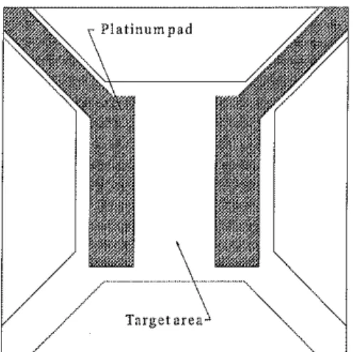
The MHP is suspended over a cavity etched in the surrounding silicon substrate by four beams. Embedded within the structure are a series of layers of various materials, as specified in Table 1. The zone between the Platinum layer 8, illustrated in Fig. 2, is designated as the target area for the Mark I prototype. For Mark 2, not shown, the geometry is quite similar. Polysilicon, located on layer 2, can dissipate sufficient power to act as a heater. The heater geometry is shown in Figs. 3 and 4 for the two geometries under consideration.
The MHP typically must operate at relatively high temperatures, around 500°C, in a controllable and reproducible manner in order to ensure spatial uniformity of temperature across the target area. It is also important that the region surrounding the micro-machined cavity incur no significant temperature rise to avoid damage to control and signal processing circuitry, integrated in the adjacent silicon substrate.
Inthe past various authors have conducted heat transfer studies [3,4,5] of MHP structures. Here, both heat transfer and heater electric potential distribution are considered, using numerical techniques. The main area of concern is that the temperature on the target surface be uniform.
The analysis considers the case ofMHP operation in a quiescent environment, i.e., in the absence of any forced convection. Trial calculations suggested the Grashof and Rayleigh numbers to be 9.8xlO'2 and 6.8xlO,2 at 450°C. Radiative losses were estimated to be only 2.4%-4.3% of total power input,
Q,
in the range 400-500 DC, assuming an emissivity of 0.7. Convection and radiation were therefore considered negligible.3/
-Si substrate Sensor Supporting Beams Figure1. Schematic of a MHP. . PolysiliconheaterFigure 3. Mark I: Heater layout. Mathematical Details
Figure 2. Mark I: Platinum layer.
- Polysilicon heater
Figure 4. Mark 2: Heater layout.
Inthe absence of convection or thermal radiation the steady-state energy equation may be written,
divAgradT
=
S (I)where the thermal conductivity, A, is a function of the location within the layers of the MHP and also of temperature. The mesh constructed was fine enough to capture the details of the heater geometry shown in Figs. 3 and 4, however some layers contain complex sub-scale microstructures, composed of different materials. Under these circumstances the cell conductivity was computed as an effective value,
ACff
=
r,A,+
r2A, (2)where
r,
=
A,j(A,
+
A,)
andr,
=
A,/(A,
+
A,)
are the area fractions of the regions occupied by materials I and 2, conductivities, A, andAz.
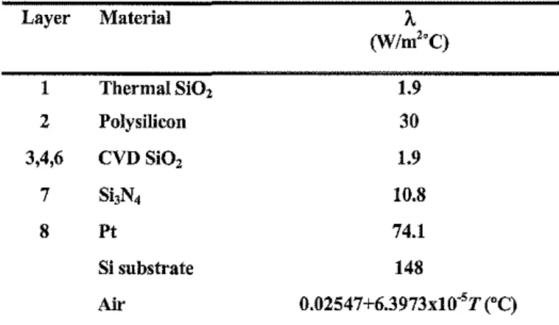
This type of approximation is often used in problems involving heat transfer in porous media.-4-Table 1. Material propertiesinMHP layers and surroundings. Layer Material A (W/m"C) 1 Thermal Si02 1.9 2 Poly,ilieon 30 3,4,6 CVD SiO, 1.9 7 ShN4 10.8 8 Pt 74.1 Si substrate 148 Air 0.02547+6.3973x1O"'T('C)
Values of thennal conductivity used, are given in given in Table 1. The correlation for air as a function temperature was computed using linear regression from the data of Vargaftik [6] in the range 27-477°C. The source terminthe heater, S (W/m\ may be presumed to be the net power consumption per unit volume of the unit,
where
Vis
the volume of the heater,V=wdl
(3)
(4) width, w, thickness, d, and length, l. The electric potential, </>, may be also be computed as a state variable according to a Laplace equation,
(5)
The source tenn, S, is then obtained as,
S
=
grad</>· crgrad</> (6)The electrical conductivity, cr, IS related to the resistance, R, and sheet resistance, R"
according to [7].
R,. - = -Rw 1
l crd (7)
Equations (1) and (5) may be converted to linear algebraic equations [8], and solved using a finite-volume method. For the electric potential, Dirichlet conditions were prescribed, corresponding to the potential across the heater, at the two ends of the element, and Neumann conditions along the sides. The latter were achieved by assuming zero conductivity, cr= 0,
outside the heater, and by using harmonic averaging [8]. A commercial computational fluid dynamics code was readily employed for the task at hand: Initially the domain was tessellated using a structured multi-block body-fitted co-ordinate (BFC) grid, i.e. the interfaces between
-5-solid and fluid zones correspond to the walls of the mesh. Subsequently a single-block Cartesian grid was constructed, so the interfaces between solid and fluid zones (silicon substrate, air, beams, and layers of the MHP structure) could cut across the cells of the mesh in thex-yplane.
PHOENICS settings
In early work [9] multi-block body-fitted grids were created. Subsequently, Cartesian meshes were deployed together with PLANT. Figure 5 shows illustrates the latter approach. TEMI is the solved-for variable; convection and built-in source terms have been disabled in GROUP 8. The stored-for variable MARK is used to identify different materials of the MHP; air, Si02, polysilicon etc. Although cell walls correspond to material boundaries in the z direction, in thex-yplane this is not necessarily the case; for instance the zig-zag shape of the heater does correspond to the mesh geometry but the diagonal beams do not. Thermal conductivities (laminar Prandtl numbers) for each material were then set in GROUND with PLANT. A fixed volumetric heat source in the heater was set in GROUP 13, while the boundaries of the grid were either set to ambient temperature or symmetry planes, as appropriate. MARK
1
1.41.011.9
1
2.32.71
3.13.6 4.0 セQTNT1
4.95.31
576.1 6.6 7.0Figure 5. Cartesian mesh together with contours ofthe variable MARK.
-6-Experimental work
Microscope
Objective
IR Detector
1
Experimental data [10] were gathered by measuring the spatially resolved black-body emission of a silicon die MHP, which had the Mark I geometry and operated in the power range 0$
Q
$ 55 mW. Figure 6 is a sketch of the apparatns. The silicon die was mounted in a standard-configuration 40 pin dip package, and wire bonded with gold connections to provide electrodes for the external power supply to the polysilicon heater lines of the MHP. An imaging resolution at the MHP of approximately 50flm was obtained using a standard microscope objective for the light collection and emission detection with a photomultiplier in the near-infrared at a wavelength of 875nm. Calibration of the infrared emission apparatns was achieved by measuring a larger (3mm x 3mm) homogeneous film of comparable emissivity on a 300flill quartz substrate, which permitted simultaneous, direct contact probing with a micro-thermocouple on the back surface. The film used for calibration was SrRu03 deposited with a thickness of approximately 250 run and sheet resistance I kOhm, by a pulsed laser ablation method [II]. The film was self-heated with a power of2W.Presentation and discussion of results
325 350 375 400
o
425o
0
Figure 7. Surface temperature distribution, Mark I design,
Q
= 34 mW.Figure 8. Surface temperature distribution, Mark 2 design.
Q
セSPュwN-7-Local temperature distribution
Figure 7 shows the surface temperature distribution for the Mark I design, at a power input of
Q
= 34 mW. The maximum temperature of 464°C occurs at the centre of the MHP.From here to the platinum pad, shown in Fig. 2, there is a temperature decrease of 40°C along a horizontal line, or 70°C along a diagonal in the direction of the beams (located at the comers of Figure 7). The desired temperature uniformity is a maximum !1Tof 10°C between the platinum contacts, i.e. there is an overheating area at the centre of the Mark I MHP design.
Figure 8 shows temperature contours for the Mark 2 design. A relatively uniform temperature distribution is apparent; it can be seen that there are four high temperature areas within the target area, near to the location of the heater turns, Fig. 4. A maximum temperature of T= 433°C is observed corresponding to
Q
セ 30 mW. The temperature at the centre of the MHP is 401°C, i.e., there a range of nearly 30°C in the temperature field across the target area. However, the temperature increases by only 5°C in a perpendicular direction from the centre, and by 18°C diagonally towards the beams prior to decreasing at the corners. The results for the Mark 2 model are still not within the 10°C design envelope, but they do illustrate the improvement in the design over the earlier Mark I prototype. The four small hot spots located in the target area hide the fact that the temperature distribution over a majority of the area of the surface is in fact quite uniform. This result is encouraging for future developments. The relatively large temperature gradient near the comers, of Figs. 7 and 8, suggests that much heat transfer occurs through the MHP beams. For Mark 2, the temperature at the connection between the MHP and the beam, is higher than for the Mark I design (330°C at 30 mW compared to 240°C at 34 mW), owing to improved temperature uniformity.In both cases, the surrounding substrate is essentially isothermal and at ambient temperature, due to the very high thermal conductivity of silicon, with large temperature gradients occurring in the air-space above and below the MHP structure. This suggests that the risk of damage to circuitry in the adjacent substrate to be minimal, provided the silicon is of sufficiently high purity that the thermal conductivity is very large.
Physical realism and numerical accuracy
Figure 9 is a comparison of the mean temperature of the MHP as computed from the present study, with that obtained experimentally [10]. Itcan be seen that agreement between experimental and numerical work is quite good in terms of slope of the profile: Predicted temperatures from the numerical analysis are nominally 20°C higher than those obtained from experiment, at a given power input,
Q:
In view of the fact that very large temperature gradients occur across the MHP surface, Fig. 3, and that the imaging resolution of the experimental apparatus was only 50llm, compared to the MHP area, A = 230llm x 230llm, forthe Mark I model; These results are to be considered as quite satisfactory.
-8-Figure 9. Comparison ofnumerical and experimental data, Mark 1 design
The results of our calculations suggest values of an overall heat transfer coefficient, U,
U=
Q
A(T-TJ
(8)to be in the range 1.71-1.76xl03W/m2°C, with a mean value of 1.73x10³ W/m2°C, whereas values obtained from the experimental data are in the range 1.81-1.89x10³ W/m2°C, with a mean value of 1.84x1 03W/m2oC,assuming an ambient temperature of 20°C. Calculated values are thus 6.0% lower than those obtained from experiments, on the average.
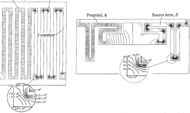
Figures 10 and 11 show details of the distribution of the potential, <1>, and corresponding
source term, S, in the Mark 1 and Mark 2 heater elements. Itcan be seen that for the Mark 1 design, grad<I> and hence S is quite constant, nominally within ±10% of the constant value
presumed in the heat transfer analysis, over the majority of the length of the heater. ln the bends however, <I> displays the well-known tendency of harmonic functions, namely the
equipotentials are closely-spaced at convex boundaries and widely-spaced at concave boundaries. It can be seen that S is a minimum of 3.1x10¹¹ at the outside comer and a maximum of 8.4x10¹² at the outside comer (inset Fig. 10). These values are approximately 170% greater and 90% less than the presumed S= 3.lx1012W/m3,and represent a significant, if somewhat localised departure from the presumed boundary condition.
Inspection of Fig. 11 (inset) reveals similar trends to those described above, for the Mark 2 geometry. In addition, variations in grad<I>also result from changes in the width,W, of the heater. Since <I> is a conservative function; potential lines are more dense in regions of
narrow width, hence S is reduced in the wider central zones of the heater.
-9-Source term, S
Gセ
lifF,i
Figure II. Mark 2 heater. Contours of potential, ep(V),and heat source, S (W/m3).
Figure
10.
Mark I heater. Contours ofpotential, ep(Y),and heat source, S (W/m3).Convergence and grid independence
Calculations were performed to assess the measure of grid independence achieved for the results of this study, i.e. to quantify the impact of the number of mesh points upon the solution. Four different sizes were considered, using the DRA method. These are illustrated below in Fig.. It can be seen that a reasonable independence of the pressure distribution from the grid size has been realized for the problem under consideration.
Conclusions
A 3-D design tool for thermal management in MHP structures was developed. Detailed calculations showed that the temperature uniformity on the target area approaches, but does not yet meet design specifications, and that the degree of insulation from the surrounding substrate is adequate. Comparison with data obtained by measuring the black-body temperature experimentally revealed good agreement, with calculated values of the overall heat transfer coefficient being 6% lower than those obtained from experiment. An investigation of the premise that the heat source may be treated as a constant volumetric source, was performed assuming metallic-type electrical conduction in the heater. The results suggest that this is a reasonable assumption for constant heater width, away from bends, but not for complex variable heater geometries, where it is an idealisation.
Recommendations
Two main areas of research are currently being pursued: (1) Experiments conducted on Mark I design indicated that the beam ends failed due to thermal stresses for
Q
セ 40 mW.-10-The impact of the temperature distribution upon stresses and strains in the beams is therefore being studied by computing the displacements from the Navier equations, concurrent with the heat transfer analysis. Time prevented the results of these calculations from being included in this manuscript. (2) The source computed from the analysis of the electric potential described above, is now being incorporated within the detailed heat transfer model.
Acknowledgement
The work contributed towards an NRC/NSERClindustry joint research project with Concordia University and Armstrong Monitoring Corporation. The authors would like to acknowledge the contributions of all the partners, including Prof. David Cheeke, Prof. Leslie Landsberger, Dr. Oleg Grudin and Mr. Radu Marinescu (Concordia), and Dr. Donald Singleton (NRC). We would also like to thank Dr. Simon Fafard and Dr. Dongfang Yang (NRC) for supplying us with experimental data. We also wish to acknowledge the contributions of three engineering students from L'Institut Catholique d'Arts et Metiers, M. Bertrand Delesalle, M. Denis Albert and M. Frederic Conte for their contributions in the early stages of this project. The technical support provided by Mr. Ron Jerome to the group is noted with appreciation.
Nomenclature B A-T S r Q V w d I 'i> (J R A U tセ Width Thermal conductivity Temperature Source term; Area fraction Power Heater volume; Heater width Heater thickness Heater length; Current Electric potential Electric conductivity; Electric resistance Area
Heat transfer coefficient; Ambient temperature Literaturereferences
I Abramson AR., Tienc.L. "Recent developments in Microscale Thermophysical Engineering". Microscale Thermophysical Engineering. 1999. pp. 3:229-244.
2 Wessel S., Parameswaran M., Morrison S.R, Frindt, RF. "A CMOS Thermally Isolated Heater Structure as a Substrate for Semiconductor Gas Sensors". Proceedings Canadian Conference on Very Large Scale Integration. Kingston. 1991. pp. 1.6.1 - 1.6.8.
3 Swart, N.R, Nathan, A "Design Optimization of Integrated Microhotplates". Sensors and Actuators A 1994. Vol. 43. pp. 3-10.
4 Allegretto, W., Shen, B. Lai, Z., Robinson, AM. "Numerical Modelling of Time Response of CMOS Micromachined Thermistor" Sensors and Materials. 1994. Vol. 6 . pp. 2.
-11-5 Fung, S.K.H., Tang,Z.,Chan, P.C.H., Sin,lK.O.,Cheung. P.W. "Thennal Analysis and Design of a Micro-hotplate for Integrated Gas Sensor Applications". Sensors and ActuatorsA. 1996. Vol. 54. pp. 482-487.
6 Vargaftik, N.B.Handbook ofthermal conductivity ofliquids and gases.CRC Press, Boca Raton. 1994.
7 L.A.A. Warnes.Electronic Materials. MacMillan. London, 1990.
8 S.V. Patankar.Numerical Heat Transfer and Fluid Flow.Hemisphere. New York. 1980. 9 S.B. Beale, F. Conte, B. Delesalle, D. Albert and M.Post "Heat Transfer in Silicon
Microhotplate Structures" Proceedings ofthe 7th Conference ofthe CFD Society of Canada -CFD99, Halifax, 30 May-I June 1999. pp.1-9 -1-14.
10 S. Fafard. Personal Corrununication. National Research Council, Canada. April 1999. 11 Sanders, B.W. and Post, M.L. "Deposition ofthin-film SrFe02.5+x by pulsed laser ablation". Materials Research Society Symposium Proceedings. 1993. Vol. 285. pp. 427-432.