Publisher’s version / Version de l'éditeur:
Proceedings of the ASPE 16th Annual Meeting, pp. 281-284, 2001-11
READ THESE TERMS AND CONDITIONS CAREFULLY BEFORE USING THIS WEBSITE. https://nrc-publications.canada.ca/eng/copyright
Vous avez des questions? Nous pouvons vous aider. Pour communiquer directement avec un auteur, consultez la première page de la revue dans laquelle son article a été publié afin de trouver ses coordonnées. Si vous n’arrivez pas à les repérer, communiquez avec nous à [email protected].
Questions? Contact the NRC Publications Archive team at
[email protected]. If you wish to email the authors directly, please see the first page of the publication for their contact information.
NRC Publications Archive
Archives des publications du CNRC
This publication could be one of several versions: author’s original, accepted manuscript or the publisher’s version. / La version de cette publication peut être l’une des suivantes : la version prépublication de l’auteur, la version acceptée du manuscrit ou la version de l’éditeur.
Access and use of this website and the material on it are subject to the Terms and Conditions set forth at
Geometric quality analysis and process control for ultra-precision laser micromachining
Bordatchev, Evgueni V.; Nikumb, Suwas K.
https://publications-cnrc.canada.ca/fra/droits
L’accès à ce site Web et l’utilisation de son contenu sont assujettis aux conditions présentées dans le site LISEZ CES CONDITIONS ATTENTIVEMENT AVANT D’UTILISER CE SITE WEB.
NRC Publications Record / Notice d'Archives des publications de CNRC: https://nrc-publications.canada.ca/eng/view/object/?id=84472028-72e7-4ab3-b483-b6406dc66f0e https://publications-cnrc.canada.ca/fra/voir/objet/?id=84472028-72e7-4ab3-b483-b6406dc66f0e
GEOMETRIC QUALITY ANALYSIS AND PROCESS CONTROL
FOR ULTRA-PRECISION LASER MICROMACHINING
Evgueni V. Bordatchev and Suwas K. Nikumb
Integrated Manufacturing Technologies Institute, National Research Council of Canada 800 Collip Circle, London, Ontario, Canada N6G 4X8
1. INTRODUCTION
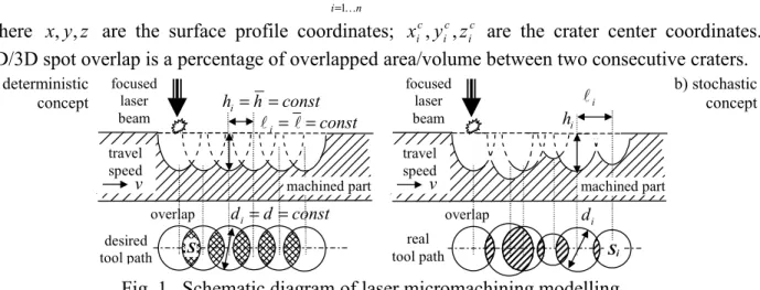
For ultra-precision laser micromachining, the need to control the process is very high because the operator has to make a host of complex decisions, based on trial-and-error methods, to set process control parameters related to the laser, workpiece material, and motion system. In addition, factors such as power fluctuations, intensity distribution, and thermal effects, not controlled by the operator, also influence the machining process. Further, the problem of choosing the optimal process parameters becomes more complicated when parts and features dimensions become smaller (less than a few tens of microns), and the thermodynamic processes within machining zone could significantly change the part geometry. To produce parts with nano/micro-scale geometric quality, using laser micro-processing technologies, a thorough understanding of the machining process and control of the entire system performance is essential. This paper describes a method for geometric quality analysis and process control aimed at improving the accuracy, precision, and surface finish of laser machined micro parts with dimensions less than 100 µm using simulation of surface profile and analysis of the machining system performance. 2. DETERMINISTIC AND STOCHASTIC CONCEPT OF LASER MICROMACHINING During the laser machining process, laser pulses are applied according to a prescribed toolpath for material removal. Each laser pulse removes a certain amount of material. The geometry and the volume of the material removed depend on the material and laser pulse characteristics. Therefore, it is important to model and control the effect of each individual laser pulse in order to control the accuracy and precision. The deterministic concept of laser micromachining modelling, shown in Figure 1a, assumes that all machining parameters such as the pulse energy,
E, the frequency of laser pulses, f , the focal spot diameter, d , and the travel speed, v, are constant. Therefore, the geometric parameters, d , v, and volume of the crater, and 2D and 3D geometry of the spot overlaps, S2D, S3D, are constant. The final surface profile of the machined part is a deterministic combination of n craters and is defined as
(
)
∑
(
)
= Ρ = Ρ n i i i c i c i c i i x y z h d z y x K 1 , , , , , , (1) where x,y,z are the surface profile coordinates; xic,yic,zic are the crater center coordinates. 2D/3D spot overlap is a percentage of overlapped area/volume between two consecutive craters.a) deterministic concept desired tool path const d di= = machined part focused laser beam travel speed v const i = l= l const h hi= = overlap S real tool path i d machined part focused laser beam travel speed v i l i h overlap Si b) stochastic concept
Experimental results [1] indicate that all process parameters of laser micromachining are non-deterministic. They are stochastic with certain mean value and variance. Based on these facts, the stochastic concept of laser micromachining modelling is shown in Figure 1b. The proposed concept is based on a realistic assumption that the variations within process parameters such as pulse energy and travel speed cause variations in each crater’s geometry. Therefore, variations within the travel speed, v~ , are a source of variation of 2D spot overlap, S~2D, even if energy is
constant. If energy varies then the crater geometry and 3D spot overlap also have random
components, e.g. d~, h~, and S~3D. Likewise, the final geometry of the machined part is modeled
as a linear combination of deterministic, Ρ
(
x,y,z)
, and stochastic, ~Ρ(
x,y,z)
, components:(
x y z)
(
x y z h d)
(
x y z)
(
x y z)
n i i i c i c i c i i , , ~ , , , , , , , , 1 Ρ + Ρ = Ρ = Ρ∑
= K (3) Deterministic component is the ideal (desired) geometry of the machined part, and can be derived from the deterministic modelling of laser micromachining. On the contrary, the stochastic component represents a difference between ideal and actual (machined) geometry. Alternatively speaking, it is the 2D/3D inaccuracy of laser machining.3. GEOMETRIC QUALITY ANALYSIS AND PROCESS CONTROL
In order to analyze the final geometric quality and to implement proper control actions, a
comparison of ideal, Ρ
(
x,y,z)
, semi-actual, ˆΡ(
x,y,z)
, and actual, Ρ(
x,y,z)
, geometries of themachined part is performed. The ideal geometry is developed from the conformance of the laser beam focal spot into the workpiece surface in accordance with the desired toolpath trajectory, to serve as a reference point for the geometric quality analysis. The ideal geometry is calculated as
(
)
∑
(
)
= Ρ = Ρ n i c i c i c i i x y z h d z y x K 1 , , , , , , (4)The semi-actual geometry, ˆΡ
(
x,y,z)
, is a result of a simulation, which utilizes the parameters ofthe actual dynamic performance of the laser machining system, e.g. actual variations within travel speed and the statistical results from the machinability study. Therefore, it is necessary to complete the two steps before simulation. The first step consists of the analysis of variations within workpiece translation movement, by measurement of the non-uniformity of travel speed to
obtain v=v+v~ and S2D =S2D+S~2D. The second step is the statistical machinability study in
order to obtain d =d +d~ and h=h+h~ as a function of E. Experimental results show that each
of these parameters randomly fluctuates around the mean value for certain pulse energy and for a particular material. Afterwards, the semi-actual geometry is calculated as
(
)
∑
(
)
= + + Ρ = Ρ n i i i c i c i c i i x y z h h d d z y x K 1 ~ , ~ , , , , , ˆ (8)The actual geometry, Ρ
(
x,y,z)
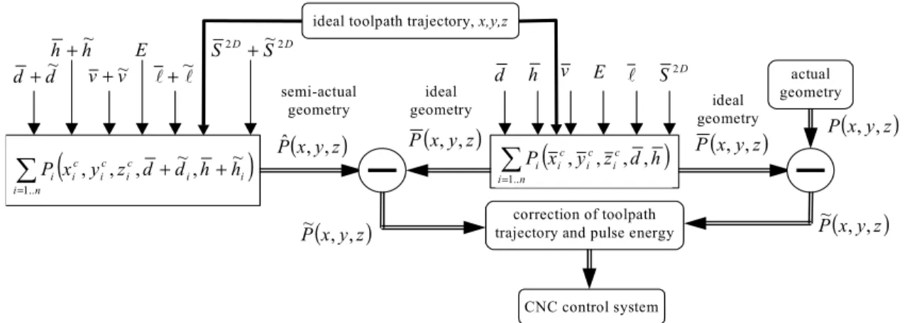
, is obtained by measuring the machined part. Each surfaceprofile has a unique data structure in the form of a polygon register that allows geometric quality parameter calculations with minimal loss of geometric information. Figure 2 shows the structure of the geometric quality analysis and process control. In order to produce a machined part at ultra-high accuracy, the appropriate correction of the toolpath trajectory and pulse energy must be implemented based on the analysis of the difference between ideal and actual geometry.
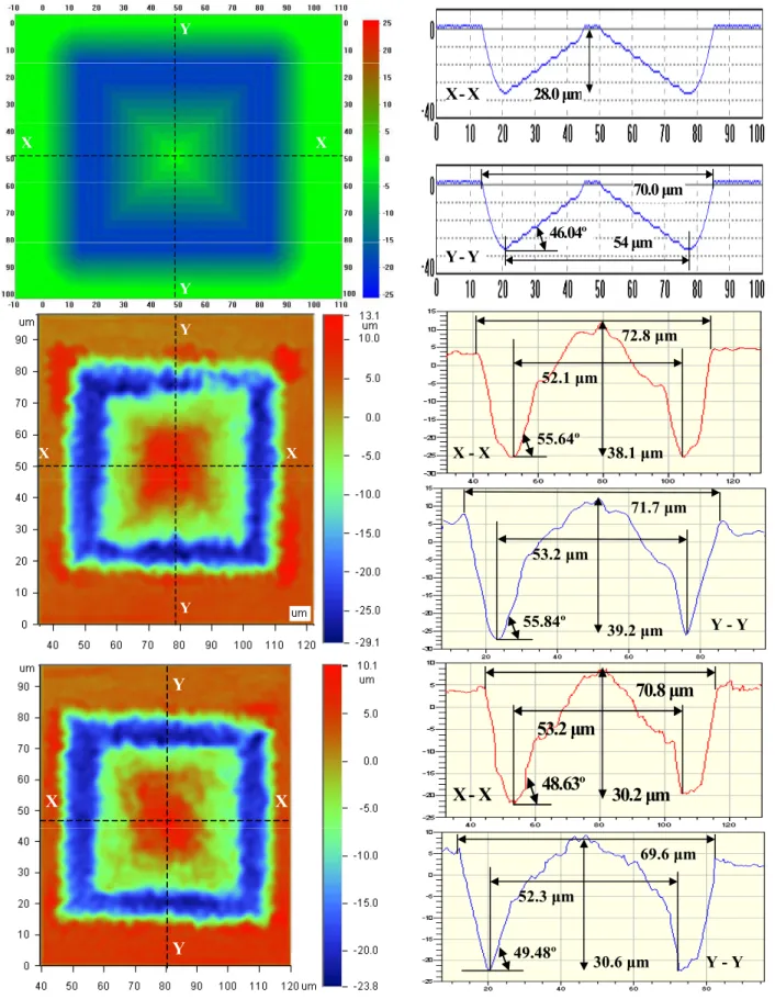
To verify the performance, a micro-pyramid (height of 28.0 µm, base area of 53x53 µm, slope of faces of 46.04º, peripheral area of 70x70 µm) was machined with a pulse energy of 16 µJ by
removing nine layers of material. To improve the accuracy of micro-pyramid, appropriate correction of the toolpath trajectory and pulse energy was applied. Figure 3 shows the ideal, actual non-corrected and corrected geometries, and profiles correspondingly in the X-X and Y-Y direction of the micro-pyramid. Table 1 contains the comprehensive analysis of these geometries. It can be seen that the machining depth is a more complex parameter to control and needs combined correction of toolpath and pulse energy simultaneously. Dimensional geometry (base and peripheral areas) is more accurate and consistent and can be adjusted by using the correction of toolpath trajectory only. Therefore, our control actions were primarily concentrated on achieving the desired height. As a result, an error in height was reduced from 10.65 µm to 2.4 µm. Also, the accuracy of peripheral area was improved from 71.25 +/- 0.55 µm to 70.2 +/- 0.6 µm. Accordingly, the slopes of pyramid faces were improved from 55.7º to 49.1º. The remaining inaccuracy is attributed to the agglomeration of burrs and heat-affected zone as a result of instabilities within laser-material interaction and pulse energy.
4. SUMMARY AND CONCLUSIONS
A method for geometric quality analysis and process control has been presented. The method improves the accuracy and precision of laser machined parts with microscale dimensions (< 100 µm). Deterministic and stochastic concepts of laser micromachining have been introduced for simulation of ideal and semi-actual geometries of a machined part. The geometric quality analysis is based on a comparison of ideal, semi-actual and actual geometries. The process control utilizes the results of geometric quality analysis and provides appropriate correction of toolpath trajectory. Experimental results confirm the usefulness and reliability of this method. REFERENCES
1. E.V. Bordatchev and S.K. Nikumb, 2001, Improving Geometric Quality Of Laser Micromachined Parts Using High-Precision Motion System Dynamic Performance Analysis,
Proc. of the 3rd World Manufacturing Congress’2001, Sept. 24-27, Rochester, NY, USA.
d h
(
)
∑
= n i c i c i c i i x y z d h P .. 1 , , , , P(x,y,z) v E l D S2ideal toolpath trajectory, x,y,z
ideal geometry d d+~ h h+~
(
)
∑
= + + n i i i c i c i c i i x y z d d h h P .. 1 ~ , ~ , , , (x y z) Pˆ , , v v+~ E l l+~ D D S S2 ~2 + semi-actual geometry actual geometry (x y z) P , , (x y z) P , , ideal geometry correction of toolpath trajectory and pulse energy(x y z)
P~ , , P(x,y,z)
~
CNC control system
Fig. 2. Schematic diagram of geometric quality analysis and process control.
Parameters of geometry Table 1
height, µm base area, µm peripheral area, µm slope, degree X-profile Y-profile X-profile Y-profile X-profile Y-profile X-profile Y-profile
ideal 28.0 53.0 70.0 46.04
non-corrected 38.1 39.2 52.1 53.2 72.8 71.7 55.64 55.84
X X Y Y X - X 28.0 µm Y - Y 54 µm 70.0 µm 46.04º X X Y Y X - X 38.1 µm 52.1 µm 72.8 µm 55.64º Y - Y 39.2 µm 53.2 µm 71.7 µm 55.84º X X Y Y X - X 30.2 µm 53.2 µm 70.8 µm 48.63º Y - Y 30.6 µm 52.3 µm 69.6 µm 49.48º