Publisher’s version / Version de l'éditeur:
Vous avez des questions? Nous pouvons vous aider. Pour communiquer directement avec un auteur, consultez la première page de la revue dans laquelle son article a été publié afin de trouver ses coordonnées. Si vous n’arrivez pas à les repérer, communiquez avec nous à PublicationsArchive-ArchivesPublications@nrc-cnrc.gc.ca. Questions? Contact the NRC Publications Archive team at
PublicationsArchive-ArchivesPublications@nrc-cnrc.gc.ca. If you wish to email the authors directly, please see the first page of the publication for their contact information.
https://publications-cnrc.canada.ca/fra/droits
L’accès à ce site Web et l’utilisation de son contenu sont assujettis aux conditions présentées dans le site LISEZ CES CONDITIONS ATTENTIVEMENT AVANT D’UTILISER CE SITE WEB.
7th Canadian Marine Hydromechanics and Structures Conference
[Proceedings], 2005
READ THESE TERMS AND CONDITIONS CAREFULLY BEFORE USING THIS WEBSITE. https://nrc-publications.canada.ca/eng/copyright
NRC Publications Archive Record / Notice des Archives des publications du CNRC :
https://nrc-publications.canada.ca/eng/view/object/?id=4a8e4322-72e8-4a67-b4f1-fb8cb46fc9e6 https://publications-cnrc.canada.ca/fra/voir/objet/?id=4a8e4322-72e8-4a67-b4f1-fb8cb46fc9e6
NRC Publications Archive
Archives des publications du CNRC
This publication could be one of several versions: author’s original, accepted manuscript or the publisher’s version. / La version de cette publication peut être l’une des suivantes : la version prépublication de l’auteur, la version acceptée du manuscrit ou la version de l’éditeur.
Access and use of this website and the material on it are subject to the Terms and Conditions set forth at
Effects of changes in hub geometry on the performance of podded
propellers in cavitating and non-cavitating open water conditions
Islam, M.; He, M.; Veitch, B.; Liu, P.
Effects of Changes in Hub Geometry on the Performance
of Podded Propellers in Cavitating and Non-Cavitating
Open Water Conditions
M. F. Islam
1, M. He
1, R. Taylor
1, Veitch B
1, Bose N
1and Liu P
21
Feculty of Engineering and Applied Science, Memorial University of Newfoundland St. John’s, NL, A1B 3X5, Canada
2
Institute for Ocean Technology, National Research Council Canada St. John’s, NL, A1B 3T5, Canada
Email: Mohammed.Islam@nrc-cnrc.gc.ca
A
BSTRACTThere are several possible explanations for the difference in performance of puller and pusher type podded propulsors. One is related to the difference in the hub geometry (hub taper angle). Puller and pusher propellers have opposite hub taper angles, hence different hub and blade root shapes. Results are presented here of an experimental study focused on the variation in performance of pusher and puller propellers with the same blade sections, but different hub taper angles, both in cavitating and non-cavitating open water conditions. In the first phase of the study, three model propellers with different hub taper angles were tested in open water conditions. In the second phase, a similar study was carried out in a cavitation tunnel. Both of the studies were done to investigate the effect of hub taper angle on performance at different operating conditions. The open water propeller data is used to provide a comparison with the cavitation performance. From the open water study, it is concluded that hub taper angle has a significant effect on propulsive performance, especially at the highly loaded condition, where the puller propellers perform better than the pusher ones. From the cavitation tunnel study, it is concluded that the puller configuration propellers do not have better performance than the pusher configuration propellers under all cavitating conditions.
1. I
NTRODUCTIONA research program on podded propellers is being undertaken jointly by the Ocean Engineering Research Centre (OERC) at Memorial University, the
National Research Council’s Institute for Ocean Technology (IOT), Oceanic Consulting, and Thordon Bearings. The program combines developments in numerical prediction methods with parallel developments in experimental apparatus. Amongst the hydrodynamic issues that have been identified are questions regarding the effects of hub taper angle, pod-strut interactions, gap pressure, and pod-strut geometry on podded propeller performance. Work is also being done on extrapolation of powering for ships with pods. Some fundamental investigations are required to fill these research gaps.
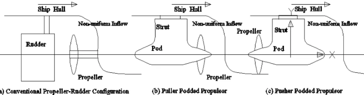
In a podded propulsion system, a propeller is attached to one or both ends of a pod shell. A motor inside the pod drives the propeller through a short shaft. The pod unit is connected to the ship's hull through a strut and slewing bearing assembly. This assembly allows the entire pod unit to rotate and thus the thrust developed by the propeller(s) can be directed anywhere over a horizontal plane over 360°. This eliminates the need for a rudder and additional appendages, such as shaft brackets as used in conventional propulsion systems [1]. A general arrangement showing the major components of two podded propulsion systems and a conventional propeller-rudder propulsion system is provided in figure 1.
Two types of podded propulsion systems are mainly used in the marine industry, namely, pusher and puller types (figure 1). Currently, more commercial vessels are equipped with puller systems. It is known from shipbuilders that pusher propellers yield a lower thrust and hence worse hydrodynamic efficiency compared to puller ones. A numerical study was performed to investigate why this is so [1]. In the
2 study it was shown how pusher and puller propellers have opposite hub taper angle (see figure 2), hence
different blade root sections, and how this change affects the performance.
Figure 1. Major components of two podded propulsion systems and a conventional propulsion system. The occurrence of cavitation on marine propellers
causes undesirable effects such as radiated noise, structural vibration, blade surface erosion and deterioration of performance. The propellers used in a podded propulsion system are vulnerable to various kinds of cavitation, which may be different when compared to a conventional propeller-rudder propulsion system. The flow conditions of a pusher and a puller propeller are different, which induces different cavitation characteristics.
Figure 2. Podded Propulsion System: puller and pusher systems; definition of hub taper angle. It is useful to perform a comparative study of a puller and a pusher podded propeller at several cavitating and non-cavitating open water conditions. This will help in judging the relative performance variation of these two propellers and if there is a superiority of one over the other. The current experimental study was carried out to fill this knowledge gap in understanding the hydrodynamics of podded propellers. The open water tests involved measurements of the performance of three bare propellers with different hub taper angles under several open water conditions. The cavitation tunnel tests involved measurements of the performance of
four bare propellers with different hub taper angles under several cavitating conditions. In all of the studies the bare propellers were tested without any pod-strut bodies attached to them, the target being the study of effect of hub taper angle. The details of the propeller design and model propellers are given in section 2. Section 3 details the experimental set-up and test conditions for both open water and cavitating conditions. In section 4 all the experimental results and relevant discussions for the performance of the propellers are provided Finally, in section 5 some concluding remarks are provided based on the experimental results and analyses.
2. M
ODELP
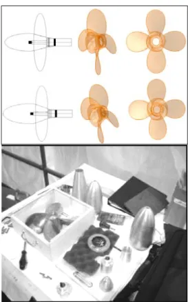
ROPELLERSThe four model propellers under investigation have the same blade sections with different hub taper angles. The basic geometrical particulars of the propellers are given in table 1. In [2] details are given of the model propellers’ geometries. The four propellers have hub taper angles of 15° (Push+15), 20° (Push+20), -15° (Pull-15), -20° (Pull-20). Figure 3 shows a photograph of the model propellers.
Table 1: Basic geometry of the model propeller. Diameter (m) 0.27 No. of Blades 4
Design adv. Coeff., J 0.8 Hub-Diameter (H/D) ratio 0.26 (based on regular
straight hub)
Section thickness form NACA 66 (DTMB Modified [3] )
Section meanline NACA = 0.8
Blade planform shape Blade planform shape was based on David Taylor Model Basin model P4119 [3] Expanded area ratio, EAR 0.60
Pitch distribution Constant, P/D=1.0 Skew Dist. Zero Rake Dist. Zero
Figure 3. Four model propellers: (a), (b), (c), (d) are the propellers with hub taper angles of +15° (push), +20° (pull), -15° (pull), -20° (pull), respectively.
3. E
XPERIMENTALS
ET UP ANDT
ESTC
ONDITIONSThe experiments in open water conditions were conducted in the towing tank facility at the Institute for Ocean Technology (IOT) using the Kempf & Remmers Dynamometer depicted in Figure 4 below. This instrumentation package allows for the measurement of propeller thrust and torque data over a range of advance coefficients.
When testing a pusher mode, conical hub propeller in the open water condition, it is necessary to use a large, bulbous nose cone to provide suitable inflow conditions to the propeller. These nose cone adapters, illustrated in Figure 5 below, were designed in accordance with the applicable ITTC guidelines [4] for open water tests and podded propellers.
Figure 4. Kempf & Remmers dynamometer: in test frame (left) and in the tow tank (right).
Figure 5. Solid model for the propellers and nose cone adapters for Push+15 (1st row) and Push+20 (2nd
row); Pictures of nose and rear cone adapters for the propellers.
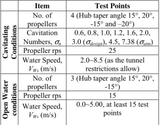
The operating rotational speed used for these experiments was selected based on data collected from a preliminary set of experiments to look for viscous effects [2]. These were conducted by measuring thrust and torque at specific J values over a range of rotational speeds to ensure the propeller was producing consistent results. The final selected rotational speed used in these tests was 15 rps. The experiments under cavitation conditions were carried out at the Institute of Ocean technology (IOT) cavitation tunnel facility. Doucet [5] detailed the tunnel configuration. Four model propellers were tested at nine cavitation numbers including the cavitation number at atmospheric pressure. For each set up, the propeller rotational speed and the static pressure in the measuring sections were maintained constant while thrust, torque and water speed were measured over a range of advance coefficients, J. The test matrix for both categories of tests is given in table 2.
In establishing the test conditions in table 2, the formulation used in [6] was used to calculate σn
4
(
)
⎟
⎠
⎞
⎜
⎝
⎛
−
+
=
2 22
1
/
n
D
P
gh
P
amb V nρ
ρ
σ
..…. (3.1)where, Pamb is the ambient pressure on the fluid
surface in Pa or N/m2, ρ is the density of the fluid in kg/m3, g is gravitational acceleration, taken as 9.81 m/s2 and h is the immersion depth of the propeller centre in m. PV is the saturated vapor pressure in Pa,
Variable n is the angular speed of the propeller in rad/s and D is the diameter of the propeller in m. Table 2: Summary of test conditions in cavitating and
non-cavitating open water conditions
Item Test Points
No. of propellers
4 (Hub taper angle 15°, 20°, -15° and –20°) Cavitation Numbers, σn 0.6, 0.8, 1.0, 1.2, 1.6, 2.0, 3.0 (σdesign), 4.5, 7.38 (σatm) Propeller rps 25 Ca vit a tin g Conditi ons Water Speed, VW, (m/s)
2.0~8.5 (as the tunnel restrictions allow) No. of
propellers
3 (Hub taper angle 15°, 20°, -15°)
Propeller rps 15
Open Water condi
tions
Water Speed, VW, (m/s)
0.0~5.00, at least 15 test points
A rotational speed of 25 rps was used in order to get low cavitation numbers below 1.0 (see equation 3.1). Video footage for all experimental conditions was taken. Later, photographs were extracted from the video clips at different operating conditions at all cavitation numbers. The air content number, α/αs [7] during the experiments varied from 0.2 to 0.4. The propellers were mounted on the upstream shaft with an axially uniform inflow. While doing the tests, the tunnel static pressure and propeller rotation speed were fixed based on the required cavitation number. After the tunnel flow was stabilized, the flow speed was changed gradually to get the required advance coefficients, keeping the rotational speed fixed. Propeller thrust and torque were measured at each operating condition.
4. R
ESULTS ANDD
ISCUSSION4.1 Effect of hub taper angle on
performance in open water conditions
The experimental results for the two propellers were collected and analyzed in terms of propeller thrust coefficient, KT, propeller torque coefficient, 10KQ,propulsive efficiency, η and propeller advance coefficient, J. KT, KQ, η and J are defined in equations
4.1-4.4, respectively.
(
2 4)
/ n D T KT = ρ ……….……..……(4.1)(
2 5)
/ n D Q KQ = ρ ………..….……(4.2)(
)
(
J / 2)
×(
KT /KQ)
= π η ………...…….. …(4.3)(
nD)
V J = A / ……… …(4.4) where, T is the thrust produced by the propeller in N, Q is the torque consumed by the propeller in N-m, ρ is the water density in Kg/m3 and VA is propellerspeed of advance in m/s.
In Figures 6 and 7 the comparisons of the open water experimental results for the propellers with taper angles of 15° with -15° and 15° with 20°, respectively are shown. It is seen that hub taper angle has more effect on performance at highly loaded conditions than lightly loaded conditions.
Measured Propulsive Performance (Push+15 vs. Pull-15) 0 0.1 0.2 0.3 0.4 0.5 0.6 0.7 0.8 0 0.2 0.4 0.6 0.8 1 Advance Coefficient, J K t, 10K q an d E ff ici en cy
Push+15_Kt Push+15_10Kq Push+15_Ef f Pull-15_Kt Pull-15_10Kq Pull-15_Ef f
Figure 6: Experimental results showing the effects of hub taper angle on the propulsive performance of propellers with hub taper angles of 15° and –15°. Quantitatively, in the bollard pull condition (zero advance coefficient) a decrease of 3.5% in thrust coefficient and 3.2% in torque coefficient were predicted for the pusher configuration propeller (Push+15°) as compared to the puller configuration propeller (Pull-15°). Again, in the bollard pull condition increases of 1.2% in thrust coefficient and 2% in torque coefficient were predicted for the Push+15° propeller as compared to the Push+20° propeller. An increase in propulsive performance for a propeller with negative hub taper angle, and a reduction in propulsive performance for a propeller with positive taper angle occurs may be attributed to two reasons. First is the change in leading and
trailing edge area in the tapered hub propellers and second is the change in root section camber due to the conical hub surface.
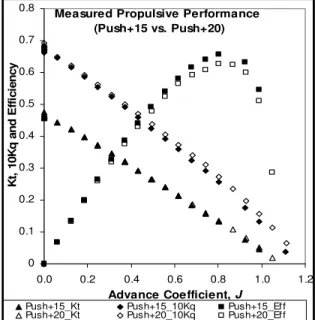
Measured Propulsive Performance (Push+15 vs. Push+20) 0 0.1 0.2 0.3 0.4 0.5 0.6 0.7 0.8 0.0 0.2 0.4 0.6 0.8 1.0 1.2 Advance Coefficient, J K t, 10K q an d E ff ici en cy
Push+15_Kt Push+15_10Kq Push+15_Ef f Push+20_Kt Push+20_10Kq Push+20_Ef f
Figure 7: Experimental results showing the effects of hub taper angle on the propulsive performance of
propellers with hub taper angles of 15° and 20°. A comparison of performance of the propeller Pull-15° and Push+20° as compared to that of the propeller Push+15° is shown in table 3. All values in the table are in percentages and a negative sign indicates that the performance of the labeled propeller is better than that of the Push+15° propeller and vice versa. It is shown that the puller propeller performs better at high and moderate loading conditions, but at lightly loaded condition (J>=1.0) the pusher propeller performance is better. Again the propeller with higher hub taper angle (Push+20) performs similarly (slightly better) to that of the propeller Push+15.
Table 3 Comparison of propulsive performance of the three model propellers.
J %Kt %10Kq %Efficiency 0.00 6.58 3.56 0.00 0.20 5.79 3.62 0.82 0.40 4.96 3.75 1.28 0.60 3.24 2.52 1.84 0.80 0.87 0.54 1.58 Pull-15 1.00 -1.47 -1.02 -9.48 J %Kt %10Kq %Efficiency 0.00 -0.97 -0.62 0.00 0.20 -0.2 -0.37 0.17 0.40 0.23 -0.65 0.87 0.60 -0.01 -1.89 1.85 0.80 -2.24 -5.5 3.10 Push+ 20 1.00 -0.97 -0.62 0.00
4.2 Taper Angle Effects on Performance
Under Cavitation
The effect of hub taper angle on propulsive performance under cavitation can be studied by analyzing the results in terms of KT, KQ and J for
different σn. Comparison of the performance of two
propellers having the same blade section but opposite hub taper angles reveals the effect of hub taper angle on performance. Figures 8(a) through 8(h) provide such comparisons (Push+15° and Pull-15°). In each figure the performance of the two propellers at atmospheric pressure is also included together with the photographs showing back cavitation at specified operating conditions of the pusher (left picture) and puller (right picture) propellers. It is seen from these figures that the propeller used in a puller podded system (Pull-15°) produces higher thrust and torque for all cavitation numbers tested and almost the entire range of advance coefficient, J. Exceptions can be seen at very low cavitation numbers (σn=0.6) at high advance coefficient (J>0.70). For this condition the puller and the pusher propellers perform almost equally.
σ=0.6; J=0.50 KT =0.114; 10KQ =0.207
σ=0.6; J=0.5 KT = 0.133; 10KQ =0.225
Performance Under Cavitating Condition (Push+15 vs Pull-15°); Fixed Sigma=0.6
0 0.05 0.1 0.15 0.2 0.25 0.3 0.35 0.4 0.45 0.5 0.55 0.6 0.65 0.7 0.75 Adv. Coefficient, J Kt , 1 0 Kq RH_A15_Kt RH_A15_10Kq RH_AN15_Kt RH_AN15_10Kq RH_A15_Kt_atm RH_A15_10Kq_atm RH_AN15_Kt_atm RH_AN15_10Kq_atm ` `
Figure 8 (a). Comparison of KT and KQ of the
6
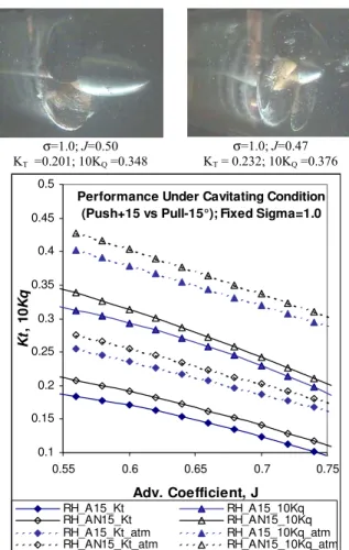
σ=1.0; J=0.50 KT =0.201; 10KQ =0.348
σ=1.0; J=0.47 KT = 0.232; 10KQ =0.376
Performance Under Cavitating Condition (Push+15 vs Pull-15°); Fixed Sigma=1.0
0.1 0.15 0.2 0.25 0.3 0.35 0.4 0.45 0.5 0.55 0.6 0.65 0.7 0.75 Adv. Coefficient, J Kt , 1 0 Kq RH_A15_Kt RH_A15_10Kq RH_AN15_Kt RH_AN15_10Kq RH_A15_Kt_atm RH_A15_10Kq_atm RH_AN15_Kt_atm RH_AN15_10Kq_atm `
Figure 8 (b). Comparison of KT and KQ of the
Push+15° and the pull-15° propellers at σ=1.0. The appearance of the cavitation patterns for the two propellers at selected cavitation numbers is presented. The test conditions together with the quantitative performance are presented with each picture. The patterns are self-explanatory and detailed discussion of all the patterns is out of the scope of the paper. The cavitation patterns at low J values varied from steady sheet cavitation on the whole surface of the blade suction side at the lowest tested cavitation number (σn=0.6), to steady/unsteady sheet cavitation with
unsteady streak cavitation on a portion of the blade surface accompanied by thick tip vortex cavitation at moderate cavitation number (σn=1.0~2.0), to thin tip
vortex cavitation at atmospheric pressure. All of the propellers show the similar cavitation patterns at the similar operating conditions.
It should be noted here that the four propellers have the same design blade sections and only differ in their hub taper angle. The blade section near the hub changes because of the solid body interaction of blade and hub. This change is responsible for the change of flow pattern around the blade root and hence the local cavitation characteristics. The
cavitation types that most influence the performance are tip vortex and sheet. The patterns of these two types are similar for the propellers. Hence the cavitation characteristics of the bare propellers do not change much at different operating conditions. The cavitation characteristics of the two propellers around the hub and blade roots were expected to vary but it was not observed. In reality, a pusher propeller operates in the strut wake, hence expected to show more unsteady cavitation characteristics than a puller propeller.
σ=2.0; J=0.56 KT =0.262 ; 10KQ =0.408
σ=2.0; J=0.56 KT =0.283; 10KQ =0.434
Performance Under Cavitating Condition (Push+15 vs Pull-15°); Fixed Sigma=2.0
0.15 0.2 0.25 0.3 0.35 0.4 0.45 0.55 0.6 0.65 0.7 0.75 Adv. Coefficient, J Kt , 1 0 Kq RH_A15_Kt RH_A15_10Kq RH_AN15_Kt RH_AN15_10Kq RH_A15_Kt_atm RH_A15_10Kq_atm RH_AN15_Kt_atm RH_AN15_10Kq_atm
Figure 8 (c). Comparison of KT and KQ of the
Push+15° and the pull-15° propellers at σ=2.0. Table 4 provides a quantitative analysis of performance variations of the two propellers operating under three cavitation numbers as compared to the performance at atmospheric pressure (equivalent to the open water condition). The percentage increase or decrease of KT and η is
indicated by a + or - sign, respectively. The amount of thrust loss for the Pull-15 propeller is almost the same or less than that of the Push+15 propeller at lower cavitation numbers as compared to the thrust produced at atmospheric pressure operating condition. For example, for the Pull-15 propeller at σn =0.6, a decrease of 58% in KT and 11% in η
occurred at J=0.54 (as compared to the same operating condition at atmospheric pressure) whereas, for the Push+15 propeller, the corresponding decreases were 61% and 14%, respectively. For the Pull-15 propeller, at σn =1.0, a
decrease of 46% in KT and 9% in η occurred at
J=0.80 (design) whereas, for the Push+15 propeller, the corresponding decreases were 54% and 16%, respectively. Again, for the Pull-15 propeller, at σdesign =3.0, an increase of 3% in KT and 3% in η
occurred at J=0.80 (design) similar to the Push+15 propeller. This analysis indicates that the percentage decrease of the KT and η at low cavitation number
with respect to the performance at the atmospheric pressure are close for the pusher and puller propellers under investigation. In other words, pusher and puller propellers with 15° hub taper angle perform equally under cavitation. The differences in performance that existed in open water operation remain the same while operating under cavitation too.
σ=3.0; J=0.55, 25 rps KT =0.263; 10KQ =0.407
σ=3.0; J=0.53, 25 rps KT = 0.292; 10KQ =0.441
Performance Under Cavitating Condition (Push+15 vs Pull-15°); Fixed Sigma=3.0
Design Cond; 25 rps 0.15 0.2 0.25 0.3 0.35 0.4 0.45 0.5 0.55 0.6 0.65 0.7 0.75 Adv. Coefficient, J Kt , 1 0 Kq RH_A15_Kt RH_A15_10Kq RH_AN15_Kt RH_AN15_10Kq RH_A15_Kt_atm RH_A15_10Kq_atm RH_AN15_Kt_atm RH_AN15_10Kq_atm
Figure 8 (d).Comparison of KT and KQ of the
Push+15° and the pull-15° propellers at σ=3.0.
Table 4. Change of KT and η for the propellers,
Push+15 and Pull-15 operating at three cavitation numbers (σν=0.6, 1.0 and 3.0) as compared to the corresponding KT and η at atmospheric pressure
condition (σatm=7.38).
J Push+15
σ=0.6 σ=1.0 σdesign =3.0
% Change in KT and KQ based on
KT η KT η KT η 0.54 -61.6 -14.5 -27.7 -6.8 1.6 1.9 0.68 -76.8 -25.0 -31.5 -7.5 2.6 2.5 0.8 -96.6 -79.7 -54.1 -16.5 3.1 3.3 0.9 - - -92.8 -73.4 3.4 4.1 J Pull-15 σ=0.6 σ=1.0 σdesign =3.0
% Change in KT and η based on
KT η KT η KT η
0.54 -58.4 -10.7 -24.9 -5.3 0.9 1.6 0.68 -75.0 -17.8 -28.9 -3.4 2.5 2.5
0.8 - - -46.2 -9.1 2.9 3.0 0.9 - - -85.1 -49.4 3.1 3.3
Figure 9 shows the effect of taper angle on KT as the
cavitation number increases at three fixed advance coefficients. The figure shows that for all the cavitation numbers, the difference in KT for the
Pull-15° and Push+Pull-15° propellers remains almost same for the three J values. This means the performance of the two propellers does not change under cavitation.
Effects of Cavitation number on Performance for Fixed Adv Coeff.
Hub taper angle: 15° (Pusher and Puller)
0 0.1 0.2 0.3 0.4 0.5 1.5 2.5 3.5 4.5
Cavitation Number, Sigma
T h ru st C o ef f. , K t Push+15_J-0.58 Push+15_J-0.70 Push+15_J-0.80 Pull-15_J-0.58 Pull-15_J-0.70 Pull-15_J-0.80
Figure 9: Comparison of performance (Push+15° and Pull-15°) variation with cavitation number for fixed
8
5. C
ONCLUDINGR
EMARKSThis research work aimed to compare the propulsive performance of a puller and pusher propeller at different cavitating and non-cavitating open water conditions. Both categories of tests revealed the effect of hub taper angle on the propellers’ performance. The following conclusions were reached from the analyses of the data acquired.
From the open water test results, it is revealed that hub taper angle has an influence on the propulsive performance of a marine screw propeller. The influence is more noticeable for highly loaded conditions than for lightly loaded conditions. In the bollard pull condition, an increase of approximately 7% in thrust coefficient and 4% in torque coefficient were measured for the puller configuration compared to the pusher configuration with hub taper angles of +15° and –15°, respectively. Again, at J=1.0 (very lightly loaded condition), a decrease of approximately 2% in thrust coefficient and 1% in torque coefficient were measured for the puller configuration compared to the pusher configuration. These variations in thrust and torque should be considered while designing propellers for different pod configurations.
In the cavitation tunnel tests, it was found that for each of the four propellers, the values of KT and KQ
tend to increase as the cavitation number, σn, is
increased from 0.6 to 1.6. As the cavitation number increased further, the values of KT and KQ decreased
before they started to stabilize at the design cavitation number of (σdesign=3.0). It is also clear from the video
footage/observation that the amount of cavitation on blade surface increased as the cavitation number decreased. All of the propellers showed similar cavitation patterns at the same operating conditions. The difference in KT, KQ and η values between the
Push+15 and Pull-15 propellers remained the same at all cavitation numbers for the entire range of advance coefficients. The difference is almost equal to the difference that exists in open water conditions. This means the changes in the performance of the pusher and the puller propellers in cavitation conditions are almost the same as each other as in open water conditions.
The open water experimental study revealed that the puller propeller performs better than a pusher propeller. The cavitation condition study revealed that the puller propeller with moderate hub taper angle performs equally as the pusher ones for all cavitation conditions tested.
A
CKNOWLEDGEMENTSThe authors would like to express their gratitude to the Natural Sciences and Engineering Research Council (NSERC), Oceanic Consulting Corp., Thordon Bearings Inc., the National Research Council (NRC) and Memorial University of Newfoundland for their financial and other support. Thanks are also extended to the staff at the Ocean Engineering Research Centre and the Institute for Ocean Technology for their assistance.
R
EFERENCES[1] Islam, M. F., Numerical investigation on effects of hub taper angle and Pod-strut geometry on propulsive performance of pusher Propeller configurations, Master’s of Engineering thesis (2004), Memorial University of Newfoundland, Canada, 136 p., 2004.
[2] Islam, M. F., Taylor, R., Quinton J., Veitch, B., Bose, N., Colbourne, B. and Liu, P., Numerical investigation of propulsive characteristics of podded propeller, In Proc. of the 1st International Conference on Technological Advances in Podded Propulsion , pp. 513-525., 2004.
[3] Jessup SD, (1989), “An Experimental Investigation of Viscous Aspects of Propeller Blade Flow”, Ph.D. Thesis, School of Eng. and Arch., Catholic University, Washington D. C., U.S.A. 249 p.
[4] ITTC – Recommended Procedures, (2002), Propulsion, Performance - Podded Propeller Tests and Extrapolation, 7.5-02-03-01.3, Revision 00.
[5] Doucet, M. J. 1992 Cavitation tunnel instruction manual. Report No. OERC92-TR-HYD-92005, Ocean Engineering Research Centre, Faculty of Engineering and Applied Science, Memorial University of Newfoundland, St. John's, NL. [6] Liu, P., Bose, N. and Colbourne, B. 2001
Incorporation of a Critical Pressure Scheme into a Time Domain Panel Method for Propeller Sheet Cavitation. International Workshop on Ship Hydrodynamics (IWSH), Wuhan, China, Sept. 22-26.
[7] Matsuba, N., Kurobe, Y., Ukon, Y., Kudo, T. and Okamoto, M. 1994, Experimental investigation into the performance of super-cavitating propellers. Papers of ship research institute, 31(5), pp. 192-251