A NEW APPROACH TO COMPONENT'S PORT MODELING
IN SOFTWARE ARCHITECTURE
Djamal BENNOUAR1, Tahar KHAMMACI2 and Abderrezak HENNI3
1
Saad Dahlab University LRDSI Lab; N° 8 09000 Blida, Algeria [email protected]
2
LINA, Université de Nantes 2, Rue de la Houssinière,
44322, Nantes, France [email protected]
3
Institut National d’Informatique Oued Smar
16000, Algiers, Algeria [email protected]
Abstract:
Nowadays, Modeling of component's port is typically based on interfaces, which heavily constrain the definition of an application's architecture. This is mainly due, to the fact that, software architecture imported only the general concepts of its fundamental elements from related fields such as computer and network architecture, and did not show interests on how these concepts are organized and used in these fields in the process of defining miscellaneous architecture.
To limit the interface constrains we have defined a port model, inspired from these related fields where the activity of defining architecture has reached a high degree of maturity. The port model is completely independent from interface concept. It allows the free manipulation of its internal structure and the specification of various controls over port and component. With these capabilities, the port model opens a new way, not supported by nowadays software architecture tools, to specify any topology an architect can imagine. In addition, the port represents one of the fundamentals elements supporting the aspect orientation of our approach to software architecture. The aspect orientation is supported through aspect ports, representing aspect's join point, which must be connected to specific aspect components.
Keywords: Software Architecture, Component, Port, ArchJava, Aspect
1. INTRODUCTION
The component represents the core element in software architecture and component’s ports play fundamental roles in the definition of a software component. The expressive power of a component model and the ease of its use, depend mainly on the quality of its external view represented by its ports. Port modeling is considered at the structural level and the behavioral level. The structural level is based on interfaces and the behavioural level is typically performed in the context of an interface [1].
The concept of ports based only on interface, constrains the free specification of various component topologies. This is due to at least the two following points:
• The topologies are specified according to the ubiquitous procedure call software mechanism, often visible at interface level. A software designer is then forced to transform any mental model of a solution in a specification which must take into account the constrains imposed by the use of interfaces.
• The connected ports must expose matching interface names and parameter types. This is not often the case, since used components may be developed by different and unrelated sources. The relevance of defining ports freely from the concept of interface was outlined in [2]. However, this orientation is not addressed in the miscellaneous research in software architecture. One reason for this situation may be the low impact of strongly related field to software, mainly, computer and network architecture. These fields represent the source of the fundamental concepts of software architecture (component, ports and connectors). However, software architecture imported only general concepts of these elements and did not show interest on advances in such field where the activity of resolving problem based on architecture definition has reached a high degree of maturity.
In our approach, called IASA (Integrated Approach to Software Architecture), the advances in the related fields were considered in the definition of the fundamental model element. For port model definition, the port structure and port organisation of hardware component (i.e. control port, address port, data port, enable port) are behind the following characteristics:: the total independence of port from interface concept, the concept of controlled ports and the concept of aspect ports.. These characteristics open new ways, not supported by nowadays software architecture tools, to specify easily, any component topologies an architect can imagine. The port model is capable to support efficiently architect's mental model of a targeted application. The semantic gap separating problem space from solution space is then extremely reduced.
The port model represents one of five key concept of IASA: component, connector, access point, SEAL action language and a design process. This paper deals mainly with the port concept. After the discussion of the related works in section 2, we briefly introduce in section 3, the component model, which represents the context where ports are instantiated. Section 4 describes the concept of access points, which is the core concept of IASA ports, and the port model. Section 5 discusses the transformation process of an abstract view of a port to its concrete view. The evaluation of the port model is outlined in section 6. It shows how the port model make easy the specification of a complex software system
2. RELATED WORKS
The external view of a component is represented by a set of interaction points used to expose the provided
and required resources of a component. Due to the different environments where researches in software architecture are conducted, various terms were introduced to designate an interaction point [3]. In ACME[4], WRIGHT[5] COSA[6] and ARCHJAVA[7] it is called port. UNICON[8] uses the term constituent and RAPIDE[9] tells it a player. C2[10], UML2.0[11] and FRACTAL[12] use the term interfaces. DARWIN[13] uses the term port to designate a type of interaction.
Usually an interaction point has a structure, showing the element providing or requiring a resource. Each interaction point may have properties specifying its communication mode (synchronous or asynchronous). We notice that this later characteristic is not directly associated with structural element of an interaction point.
In ArchJava[7] the port, representing an interaction point, is composed of method signature. Each method corresponds either to a provided service or to a required service. UML2.0 [11] defines a port as a regrouping technique of provided and required interfaces. A C2 interaction point is oriented to support communication by messages in the context of particular architectural style oriented to GUI design. The C2 [10] interaction point is either a requests or a notification.
RAPIDE[9] distinguish between three kind of interaction points called constituents: provides, requires and actions. The constituents provides and requires are oriented to handle synchronous interaction. These constituents are represented by functions. The constituents actions are oriented to support asynchronous interaction based on event. In UNICON[8], all interaction points, called players, are predefined and correspond to well known software mechanisms (i.e. RPCCal, ReadFile, StreamIn etc..).
In the DARWIN[13] ADL, an interaction point is associated with a type of service handled by a method and an interaction type specifying how the service may be launched. For example, the trace services are handled by events. They correspond to an asynchronous communication mode. The outputs and inputs services are handled by the port interaction type, which operate in synchronous communication mode.
WRIGHT[5] does not specify any internal structure or any grouping technique for the port. WRIGHT's port, is a CSP[5] specification describing the expected behavior of the component at that port.
3. CHARACTERISTICS OF IASA PORTS
We present in the following the main characteristics of the IASA port and we outline the capabilities of just introduced tools and models regarding the support of such characteristics.
a-The total independence from interface concept: This characteristic provides the following possibilities:
- The software mechanism is completely abstracted during software composition process. Such an abstraction allows the designer to elaborate various
topologies without any constraints from the concept of interfaces directly related to software mechanisms. The WRIGHT approaches reach this goal, by the support of reasoning at high level of abstraction. However WRIGHT do not support the abstraction refinement.
- The structural elements of port may be accessed independently. In current software architecture models and tools, an interaction point, usually represented by interface, is considered as an atomic element despite its complexity. It is not possible to deal separately with element defining the structure of an interaction point (i.e. method, method parameters). A connexion's end point, usually named role, is connected only to an interface. It is not possible to define a connexion between interface elements as shown in figure 1.
- The structural element of port may be initialized. This possibility opens the way to specify default values for interaction point. The default values play an important role when connecting two ports with different number of interaction point. In such situations, a provided service does not require from its user to bring all necessary resources, especially, when the service user has no mean to specify all required resources. Initializing an interaction point is a concept not supported by current models and tools.
b-Aspect Oriented Architecture: The specification of the application's architecture is in fact a kind of Aspect Oriented Programming. The first separation of concerns met is software architecture is the separation of communications supported by first class connector from the business logic supported by components. However, communication is not the sole aspect found in software design. Logging, error handling, state reporting, data persistence, security are other common aspects which cut across component's business logic. Introducing aspect in software architecture will make design of complex software an easier task and will yield clear and lucid specification. The port model reinforces the aspect orientation of the IASA approach through the definition of specific aspect ports, which represent the aspect join point. In IASA, handling an aspect is realized by connecting an aspect port to an aspect component. All previously introduced models and tools do not provide support for aspects.
c- Control over port and components: controls over ports and components include operations such as: 1) enabling port or a component to operate, 2) starting, pausing, stopping and restarting services on port 3) controlling the access to resources exposed on ports.
Figure 1: Connections based on port's element Access point (method, parameter) Port (Interface)
A
B
D
C
The support of such controls will give the port a central role in dynamic architecture (i.e. dynamic component updating). The specification of control over ports and components has been addressed partially in some project such as SOFA/DCUP[14] and OLAN[14], but for specific purpose such as component administration in OLAN and dynamic component replacement in SOFA/DCUP. Controlling ports and component as part of the business logic of a component seems to be not addressed in software architecture.
d- Behavioral port modelling: Typically, two techniques are used for modelling behavior observed on a port: discrete behavior modelling called also static modelling[1] and continuous behavior modelling referred also by the term interaction modelling[1]. Discrete behavior describes the visible properties of a system at specific snapshots during the system’s execution. This is achieved primarily by using invariants on the component states and pre- and post-conditions associated with the component's operations. Discrete behavior is not expressive enough to represent how the ports interact with its environment, how it reaches some state and when its miscellaneous services may be used. The interaction behavior modeling is more accurate since it allows the specification of the allowed execution traces of the provided or required services.
Usually, specifying interaction protocols is done using formal approaches such as CSP[5], Finite Sate Machines[16], regular languages[17], and temporal logic[18]. These approaches focus on detailed formal models of the interaction protocols and enable proofs of protocol properties. However, due to their mathematical notation and orientation, these techniques are too formal and complex for routine use by practitioners. In order to provide practitioner with familiar tool for specifying the port's behavior, IASA port use an Action Language, inspired from UML Precise Action Semantic[19], called SEAL[20]. The interesting capability of such language is its easy extension and the support of action context dedicated to specify interaction behavior.
e- Standard port: While reasoning at high level of abstraction, an architect often uses instance of abstract component and link them by a well-known or standard connector. Such action highlight that even in an early stage of design process, while various component are seen at high level of abstraction, the architect often choose the implementation technology of connector. This kind of activity must be considered by providing ports supporting this various interconnection technology. Examples of such ports includes port oriented to support standard protocol (i.e. FTP, HTTP, SOAP) standard middleware (CORBA, RMI), and interaction with standard execution environment (operating systems, application servers). Predefined ports have been addressed only in UNICON which provide architect with a restricted number of port. However UNICON do not define any mean to introduce ports supporting other interconnection technology.
4. THE IASA PORT ENVIRONMENT
In order to clearly understand the port model, we briefly introduce in the following the IASA component which is the place where ports are instantiated. Through port, the IASA component highlights its provision, requirement and aspects. The full description of all the IASA models are presented extensively in [21]
4-1 THE IASA COMPONENT MODEL
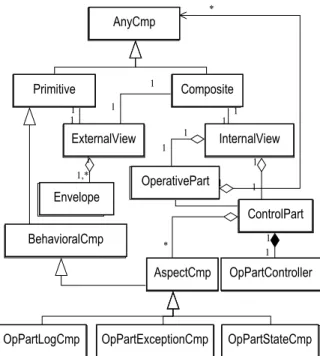
The component model defines a specific organization either for the external view applicable to any component (primitive, composite, COTS, legacy code) or for the internal view. The external view is represented by the concept of envelope, which hosts component's ports. The internal view (Figure 2) is composed of two parts: the operative part and the control part. The operative part contains component realizing the business logic. The control part contains a number of aspect oriented components and a component dedicated to control the operative part. Currently, the component model supports three aspects: logging, error and state. An aspect component has an external view made of specific ports called aspect ports.
4-2 ASPECT COMPONENT
An aspect component is the central place where an aspect is managed. An aspect component is a behavioural component, completely specified in the SEAL action language. An aspect component has two instantiation modes: active and passive mode. In active mode, the connexions of all aspect port belonging to the same aspect are performed by the aspect component.
4-3 THE ENVELOPE CONCEPT:
The main goal of the envelope is to provide a total isolation of the internal view from the external world. The envelope hosts all the resources needed to support communication aspect (i.e. adapters) and to enable the
Figure 2: Global view of the component model
AnyComponent Primitive Composite InternalView ExternalView Envelope OperativvePart ControlPart AspectCmp OpPartController
OpPartLogCmp OpPartExceptionCmp OpPartS tateCmp BehavioralComponent * 1 1,* 1 1 1 1 1 1 1 1 1 1 * 1 1 1 OpPartExceptionCmp OpPartStateCmp OpPartController BehavioralCmp OpPartLogCmp AspectCmp ControlPart OperativePart InternalView ExternalView Composite Primitive AnyCmp Envelope
specification of connexions involving the port's structural elements. The envelope represents a sort of clothes an instance of a component type wears in a specific situation. Hence, it is possible to associate instances of the same component type with different envelopes either in the same composite or at a different level of the hierarchy describing a composite.
5 THE IASA PORT'S BASIC CONCEPT
The port model has an internal structure made of element called access points. An access point is the smallest structural element defining a port. A port may be provided with a behavior specifying how the port must be operated.
5-1 THE ACCESS POINT CONCEPT
An access point is the basic element exposing required or provided resources (Figure 3). Communication mode and the resource time validity are among its properties. An access point is instantiated inside a port and it may be wired, in an independent manner, to another access point which is hosted in the same port or in a different port.
In order to allow more precise and practical specification, we have introduced more precise access point, according to the global role they play in a component: the DataPoint and the ActionPoint.
A DataPoint (Figure 3, figure 5) is used to transfer data of any type. It is provided with an attribute specifying the data direction (in, out, and inout). The definition of new specific DataPoint follows a specific style for naming and definition. The naming style uses the data type name followed by DataPoint (i.e. IntDataPoint). The definition style is based on the name of the supported data type and a template file written in the targeted language (Figure 4).
An ActionPoint (Figure 3, figure 5) represents a service, which may support many distinct actions. An action point is provided with a set of actions supported by the service (actionSet). Regarding the associated
service, an access point plays one of two basic roles: a server role played by the ServerPoint or a client role played by the ClientPoint (Figure 3, figure 5).
The ServerPoint manages a second set of actions called the refinedActionSet. Each element of the refined action set is associated with only one action in the actionSet. A refinedActionSet describes one step further, the refinement of the associated action (Figure 6).
5.2 SPECIFIC ACCESS POINTS:
The specific access points are oriented to support specification of controls and to highlight the various aspects considered in the design of components.
a- Aspect access points: For now the IASA IDE supports three predefined aspects: logging, state and error. Each aspect is supported by a specific DataPoint. The state aspect is handled by GlobalStatePoint which deals with the stability of a design (STABLE and
package iasa.datapoints; // StringDataPoint Definition public class StringDataPoint extends DataPoint{ private String data;
StringDataPoint(StringDataPoint sdp, int dir) { copy(sdp); this.dir = dir;}
StringDataPoint(String s, int dir) { data = new String(s); this.dir = dir; this.timeValidity = 0; }
String get() throws InvalidAccessToInDataPoint, AccessPointTimeOut { getValidate(); return new String(data); }
void set(String s) throws InvalidAccessToInDataPoint, AccessPointTimeOut { setValidate(); data = new String(s);} public void copy(DataPoint dp){
data = new String(((StringDataPoint)dp).data); } public void startTimer(){}
}
Figure 4: StringDataPoint in ArchJava
ServerPort DataPoint
out in inout
with initializer aspect ActionPoint
ServerPoint ClientPoint ControlledServer EnableDataPoi
nt. Controlled Ports
DataPort Figure 5: Access Points and ports
Fig 6: actionSet and refinedActionSet sap1.A
// ActionSet {a0 , b0, aA0} //RefinedActionSet {{aA0 = {a0, b0, a1}}}
cap2A //ActionSet {a2} sap2.A
{d0 , e0} /* ActionSet*/ {} // RefinedActionSet :A
cap1.A // ActionSet {a1, aB0} b:B
Figure 3: The access point model DataPoint AnyPoint ActionPoint Actionset S everActionPoint ClientActionPoint RefinedActionS et S tateDataPoint ExceptionDataPoint
LongDataPoint ActionS tateDataPoint AspectDataPoint AspectCmp * 1 1 1 1 * LogDataPoint ActionStateDataPoint RefinedActionSet ExceptionDataPoint ServerPoint ClientPoint StateDataPoint AspectDataPoint AspectCmp DataPoint ActionPoint ActionSet AnyPoint
UNSTABLE values) and StructuralStatePoint which reports the component’s structure at a quite precise time. The error and logging aspects are successively handled by ExceptionDataPoint and LogDataPoint. b- Controlled access point: The control may be seen as another aspect. However, since most controls are supported by actions, control aspect is actually considered as part of the core business aspects of an application. The access points dedicated to controls are concerned by 1) reporting the state of services through ServiceStatePoint, 2) performing control action on services through ControlledServerPoint and 3) controlling the availability of a port through EnableDataPoint. The values ENABLED, DISABLED, STARTED are examples of services state reported by the ServiceStatePoint, The ControlledServerPoint (figure 5), is a specific ServerPoint provided with control actions such as: enable, disable, start, stop, restart and terminate. EnablelDataPoint (Figure 5) is an in data point which accepts ENABLE and DISABLE values.
5-3 PORTS:
A port is a grouping technique of related access points and represents a namespace. It maintains an abstract view and a concrete view. The abstract view is represented by the concept of access point, the actions associated with action point and a behavior. The port's behavior is represented by a set of valid rules defined in the SEAL action language.. Each rule shows how the required or provided resource must be used. While connecting two ports, the connector is said to be valid, if the supported interaction use compatible port's behaviors. Figure 7 shows a partial description in SEAL language of ports of the component X25CM (Figure 8).
The concrete view may be any model, provided with a clear way leading to the implementation level (i.e. interface based port, UML port, ArchJava port)
For an efficient and clear specification of connections between components, we have defined a number of ports organized in four categories: regular ports, aspect ports, controlled ports, and standard ports.
Four predefined regular ports were defined: ClientPort, ServerPort, PeerPort and DataPort. A ClientPort must contain one ClientPoint and zero or more DataPoint. A ServerPort, contains one ServerPoint, a number of DataPoint and a number of ServiceStatePoint. A PeerPort contains one ServerPoint, one ClientActionPoint, a number of DataPoint and any number of ServiceStatePoinjt associated with the ServerPoint. A single port is associated with a single service.
A controlled port is any port provided with EnableDataPoint, or a ServerPort provided with the ControlledServerPoint instead of a ServerPoint, or provided with both control techniques. An aspect port is composed of aspect point belonging to the same aspect. The three predefined aspect are supported by the StatePort, the ExceptionPort and the LogPort.
Standard ports are oriented to support well known connectors such as a standard protocol and the
interaction with a standard environment such as an operating system or an application server. The predefined ports are provided with a clear concrete view corresponding to a well known implementation. HTTPClientPort, CORBAClientPort, EJBClientPort, UnixPort are examples of such ports, prepared for use with specific connectors, such as the HTTP protocol, the Corba Bus, the EJB component model and the UNIX operating system. The ports such as FTPServerPort and HTTPServerPort, represent the server side of standard protocols. Such ports are provided only with an abstract view. Their concrete view is fully defined in the server side.
6- GENERATION OF THE CONCRETE VIEW The abstract view of a IASA port provides facilities to specify freely various topologies of components. The process of generating the concrete view depends on the specified topology and the deployment of interconnected component. This process comprises the following steps:
package x25cm; import license.ethernet; component X25CM {
ports { // external view: structure and behavior . . .
FTPClientPort pFtp {// FTP Client Port Description accesspoint{
ClientActionPoint cFtpAp (0, SYNC);
StringDataPoint cFtpReplies (IN, 0, SYNC) }
actioncontext{
use system.FTPIntercationContext; }
behavior{ // pFtp behavior boolean ftpConnexionSet = false; rules getTicketFile, ftpReset; rule getTicketFile {
precondition: ftpConnexionSet; pattern: rename(O_NAME, N_NAME), get(N_NAME), delete(N_NAME), success; fail ftpReset;
postcondition: ; }
rule ftpReset { precondition:; pattern: close, success;
postcondition: ftpConnexionSet = false; }
. . .
} End Description of X25CM component
Figure 7: Partial Seal Description of X25CM's ports
pMAin :MainCmpPort pFtp :FtpClientPort pSql : SqlClientPort pPrinter : PrintSpoolerPort pAlarm :LogDataPor licenseFile:FSClientPort fire: Action
:X25CM
a- The normalizing step: This step yields a topology where IASA ports are transformed on interface based ports (i.e. an IDL description, a Java Interface description, an ArchJava port).
b- Generating port in a targeted language: This step is concerned with the following three actions: 1) providing port with necessary adapters 2) solving the distance problem [21] between connected ports 3) attaching the port to a connector endpoint, often called a connector role. In the following, we focus the study on the normalizing step.
6-1 THE NORMALIZING STEP RULES
The transformation process uses many rules in order to generate an interface based architecture. We highlight in the following the main rules in order to illustrate this step.
- An action point corresponds to methods requiring or providing the associated service. A SEAL action is handled by one method. (figure 11)
- A DataPoint may be involved in more than one action of a ServerPort. The associated methods to action represent the carrier service of data in that DataPoint
- When a DataPoint is wired in an independent manner, its is associated with a service carrier hosted by the envelope and composed by a set an a get methods. The actual method used to transfer data depends on the connector and direction of DataPoint. If the connector direction is from an OutDataPoint to an InDataPoint, the transfer of data is initiated by the OutDataPoint. The transfer method used is the set method provided by the InDatapoint. If the connector direction is from an InDataPoint to an OutDataPoint, the transfer of data is initiated by the InDataPoint and the transfer method is the get method provided by the OutDatapoint.
7- VALIDATION OF PORT MODEL
The port model was validated in the context of the IASA approach validation process. One step of this validation process was concerned by the design and implementation, according to the IASA design process, of a commerce manager of an X25 network's product. The target language in this validation was the ArchJava ADL. We present in the following some steps highlighting how the port model were used.
Figure 9 shows the internal view of the X25CM component which in fact is the targeted application. In this internal view, we notice that the instance x25 of X25CM_CORE component type uses a controlled port as its main port. According to the wiring plan, the X25CM_CORE will operate only if controlled data point (EnableDataPoint) on the main port, receives an ENABLE value from the LicenseController component.
Figure 10 shows the internal view of the component type LicenseController. This view highlights the core business aspect of LicenseController The gma client port of starter and the server port of EtherAddrReader are linked by a full connector[21]. Usually, in a full connection, all the access points related to the service must be connected to corresponding points in the client
port. The IASA approach enables the specification of default values for DataPoint, either to freeze the behavior of a service or to discharge the client from providing all access points. In such situation, the client's port does not need to be provided will all access points.
The client port of the starter and the server port of EtherAddrReader, are both mapped to methods with one parameter as shown in the SEAL description in the figure 11. The DataPoint at each side of the connection
LicenseLoader EtherAddrReader LicenceGen Action: licenseGet OpPartController: starter Action: getMacAddr macAddr Action: buildLicence licenseData licenseData
= =
ENABLE/ DISABLE licenseLoad Action: compare gma blic cmp licl pMain pMain pMain enable pMainFigure 10: Internal view of LicenseController
package license.ethernet; component LicenseGen{
ports { // external view: structure and behavior MainCmpPort pMain {
accesspoint { // Port Structure
ServerActionPoint pMainAp (0, SYNC);
StringDataPoint licenseData(OUT, 0, SYNC); StringDataPoint macAddr(IN, 0, SYNC);}
actioncontext{
action buildLicense implemented by macAddr buildLicense (licenseData);} behavior{ // Port's rules description ……….} } // End of pMain description
. . . } // End description of LicenseGen Component Figure 11: partial description of LicenseController
LogDataPort: pAlarm OpPartLogCmp MainCmpPort: fire FtpClientPort: pftp SqlClientPort: pSql X25CM OpPartController MainCmpPort::fire LicenseController: lc X25CM_Core: x25 PrintSpooler: pPrinter lc FSClientPort:licenseFile Action:licenseGet MainCmpPort fire enable x25
Figure 9: Internal View of X25CM component Control Part
corresponds to the method's parameter. This latter may be the return value or a parameter of the methods at both side of the connector.
The DataPoint of the EtherAddrReader’s port is directly linked to a DataPoint of the LicenceGen’s port. This is done by using a primitive connector[21]. The two points are then associated with a transport services hosted by the component's envelope. As stated before, the transport service type depends on the direction of the primitive connector. The arrow is usually attached to the point providing the transport service. In that case, the service is a setter provided by the LicenseGen's DataPoint.
This kind of connector appears also in the connection between the DataPort of the comparator (component with == symbol) and the LicenseReport component. The direction of the connector states that the transport service is located at the LicenseReport port and the DataPoint direction states that the data source is also at LicenseReport. In this situation, the transport service is a getter provided by the DataPoint of the LicenseReport component.
The set and get services are connected by delegation connector to internal set and get if they exist, otherwise these services are defined and hosted in the envelope.
7-1 NORMALIZING STEP USING ARCHJAVA Normalizing a IASA architecture using ArchJava is achieved according to the following complement rules:
- An instance of a IASA ServerPort is mapped to an ArchJava port, which contains only provided method.
- A ClientPort is mapped to an ArchJava port containing only required method.
- The instance names of IASA elements (ports, access point, action) are used for naming the associated ArchJava elements
The code in figure 12 shows an ArchJava port representing the pMain port of LicensedLoader, the pftp port of X25CM and the licenseLoad action.
The normalization process applied to the pMain port of LicenseGen component, partially described with SEAL in figure 11, yields three ArchJava ports as shown in the code of figure 13
This normalization process assumes that internal access point and ports, which are connected to the external port by delegation connector, are provided with the get and set methods. However, in case where the internal ports do not provide setters and getters, the transformation process use the envelope to provide necessary support. In the following we show how this support is hosted in the envelope.
7-2 NORMALIZING WITH THE ENVELOPPE Figure 14 shows the generated code of the LicenseGen component's envelope and its ports. The envelope is represented by an ArchJava component (LicenseGenEnvCmp). The methods associated with envelope's DataPort do not give direct access to internal data representation. The envelope ensures complete isolation of internal elements from the external world.
Moreover, before actually performing the buildLicense method, the envelope start by cashing all data associated with InDataPoint. Once the buildLicense return, the envelope performs cashing of
public port pMain_licenseLoader { provide void licenseLoad(); } public port pftp {
require String connect(String hostName); require String sendUserName(String userName); require String sendPassWord(String userName); require String close();
// etc . . . .}
Figure 12: pFtp and pMain of LicenceLoader
public port macAddr_mainPort_licenseGen { provide void setMacAddr(String macAddr); require String getMacAddr (); }
public port licenseData_mainPort_licenseGen { provide String getMacAddr ();
require void setMacAddr(String macAddr);} public port pMain_licenseGen {
provide String buildLicense(String macAddr);} Figure 13: pMain of LicenseGen
public component class LicenseGenEnvCmp { StringDataPoint envLicenceData =
new StringDataPoint("", DataPort.OUT); StringDataPoint envMacAddr
new StringDataPoint("", DataPort.IN); // Internal ports reference
DataPort internalMainPort; // Provided services
public port pMain_licenseGen { provide StringDataPoint
buildLicense( StringDataPoint macAddr);} // Data Ports
public port macAddr_mainPort_licenseGen { provide void
setMacAddr(StringDataPoint macAddr); require StringDataPoint getMacAddr(); } public port licenseData_mainPort_licenseGen { provide StringDataPoint getLicenseData(); require setLicenseData( StringDataPoint licenseData);} // Implementation public StringDataPoint buildLicense(StringDataPoint macAddr) { envMacAddr.copyData(macAddr) envLicenseData.copy(new internalMainPort.buildLicense( envMacAddr.getRef())); return new StringDataPoint(envLicenseData);} public void setMacAddr(
StringDataPoint macAddr){ envMacAddr.copyData(macAddr)} public StringDataPoint getMacAddr (){ return new StringDataPoint(envMacAddr);} public void setLicenseData (
StringDataPoint licenseData){ envLicenseData.copyData(licenseData) } public StringDataPoint getLicenseData(){ return new StringDataPoint(envLicenseData); } }// End of envelope component
all data associated with OutDataPoint. For inout DataPoint, cashing is performed before and after method execution.
8- CONCLUSION
The IASA port model reaches many important objectives due to its various characteristics, such as the total abstraction of software mechanism, the support of aspects, the concept of controlled ports, the support of standard connectors and the participation of ports in component validation process.
The abstraction of the software mechanism enables the manipulation of port's elements and the specification of various component topologies without any constrains typically imposed by the software mechanism.
The definition of specific ports, each one oriented to support a specific component’s aspect, will produce more organized architecture specification, where each aspect is considered in an independent manner.
The controlled ports enable the specification of various controls over a whole component or on its services. This later characteristics opens the way to the specification of dynamic and complex component topologies.
The IASA port model through the standard ports, enables the use at a high level of abstraction of well known interconnection technologies, mainly the standard internet protocols, the middleware communication infrastructure, and the access to run time environment.
Embedding SEAL actions in ports and the marking concept of ports gives these later an important role in the validation process of software architecture at a high level of abstraction.
The port model represents a fundamental element in the ECLIPSE based IASA IDE. Currently, the IASA IDE uses ArchJava as a target language in the normalization process. However, since ArchJava, don’t easily and efficiently support various and complex deployment scheme, we are now studying the introduction of Java and UML2.0 as new target languages for the IASA IDE.
REFERENCES
[1] Roshandel R., Medvidovic N. “Relating Software Component Models”,TR,USC-CSE-2003-504, 2003. [2] Carrez, Cyril Behavioral Contracts for Component. PHD Thesis, ENST, Paris 2003 (In Frensh).
[3] N. Medvidovic and R.N. Taylor. A Classification and comparison framework for software architecture languages, IEEE TSE, 26(1):70-93, 2000
[4] Garlan, D., Monroe,:Acme: Architectural Description of Component-Based Systems. Foundations of Component-Based Systems, Leavens and Sitaraman (eds), Cambridge University Press, 2000.
[5] R. Allen : A Formal Approach to Software Architecture. PhD thesis, School of Computer Science, Carnegie Mellon University, 1997
[6] M. Oussalah, A. Smeda and T. Khammaci, An Explicit Definition of Connectors for Component-Based
Systems. Proceedings of the 11th IEEE International Conference on the Engineering of Computer Based Systems, Brno, Czech Republic, May 2004
[7] Aldrich, J. 2003. Using Types to Enforce Architectural Structure, Computer Science and Engineering PHD Thesis, Washington University, [8] Shaw, M., DeLine, R., Zalesnik, G.: Abstractions and Implementations for Architectural Connections. Proceedings of the 3rd International Conference on Configurable Distributed Systems, May 1996
[9] D. Luckham, J. Kenney, L. Augustin, J. Vera, D. Bryan and W. Mann. Specification and Analysis of System Architecture Using Rapide. IEEE TSE, vol. 21(4) :336-355, april 1995.
[10] Nenad Medvidovic, Architecture-Based Specification-Time Software Evolution, Phd Thesis, UNIVERSITY OF CALIFORNIA, IRVINE, 1999 [11] Unified Modeling Language: Infrastructure, version 2.0, 3rd revised submission to OMG RFP ad/00-09-01, January 2003
[12] E. Bruneton, T. Coupaye, M. Leclerc, V. Quéma, J.-B. StefaniThe Fractal Component Model and its Support in Java Software Practise and Experience. 36(11-12):1257-1284. 2006
[13] J. Magee, N. Dulay and J. Kramer, “Structuring Parallel and Distributed Programs”, IEE Software Engineering Journal, Vol.8, No.2, March 1993
[14] D. Balek : Connectors in Software Architectures. Ph.D. Thesis, Faculty of Mathematics and Physics, Department of Software Engineering, Malostransk [15] R. Balter, L. Bellissard, F. Boyer, M. Riveill, J-Y. Vion-Dury : Architecturing and Configuring Distributed Applications with Olan. In Proceedings of IFIP International Conference on Distributed Systems Platforms and Open Distributed Processing, (Middleware'98), The Lake District, September 1998. [16]Yellin D.M., Strom R.E., “Protocol Specifications and Component Adaptors,” ACM Transactions on Programming Languages and Systems, V19,N°2, 1997. [17]Plasil F., Visnovsky S., “Behavior Protocols for Software Components”, IEEE Transactions on Software Engineering 28(11), pp. 1056–1076, November 2002. [18]N. Aguirre, T.S.E. Maibaum : A Temporal Logic Approach to Component Based System Specification and Reasoning. In Proceedings of the 5th ICSE Workshop on Component-Based Software Engineering, Orlando, FL, 2002
[19] OMG. Action semantics for the UML, Final submission. TR, Object Management Group, 2001 [20] A. Saadi, D. Bennouar. A Simple and Extensible Action Language for the IASA IDE, IR, N° SA-005-06, LSDRI Lab, USDB at Blida, Dec 2006 (In French) [21] D. Bennouar: The IASA Approach, Internal Report, N° SA-002-07, LSDRI Lab, USDB at Blida, April 2007 (In French)