Publisher’s version / Version de l'éditeur:
IEEE Expert, 10, 2, 1995
READ THESE TERMS AND CONDITIONS CAREFULLY BEFORE USING THIS WEBSITE. https://nrc-publications.canada.ca/eng/copyright
Vous avez des questions? Nous pouvons vous aider. Pour communiquer directement avec un auteur, consultez la première page de la revue dans laquelle son article a été publié afin de trouver ses coordonnées. Si vous n’arrivez pas à les repérer, communiquez avec nous à [email protected].
Questions? Contact the NRC Publications Archive team at
[email protected]. If you wish to email the authors directly, please see the first page of the publication for their contact information.
NRC Publications Archive
Archives des publications du CNRC
This publication could be one of several versions: author’s original, accepted manuscript or the publisher’s version. / La version de cette publication peut être l’une des suivantes : la version prépublication de l’auteur, la version acceptée du manuscrit ou la version de l’éditeur.
Access and use of this website and the material on it are subject to the Terms and Conditions set forth at
Using a Blackboard to Integrate Multiple Activities and Achieve
Strategic Reasoning for Mobile-Robot Navigation
Liscano, R.; Fayek, R.; Manz, A.; Stuck, E.; Tigli, J.
https://publications-cnrc.canada.ca/fra/droits
L’accès à ce site Web et l’utilisation de son contenu sont assujettis aux conditions présentées dans le site
LISEZ CES CONDITIONS ATTENTIVEMENT AVANT D’UTILISER CE SITE WEB.
NRC Publications Record / Notice d'Archives des publications de CNRC:
https://nrc-publications.canada.ca/eng/view/object/?id=8b3a59ab-c1de-449e-829d-97bf7a181781
https://publications-cnrc.canada.ca/fra/voir/objet/?id=8b3a59ab-c1de-449e-829d-97bf7a181781
Using a Bla ck boa rd to
Inte gra te M ultiple Activitie s
a nd Achie ve Stra te gic
Re a soning for M obile - Robot
N a viga tion
Ramiro Liscano, Allan M anz, and Elizabet h R. St uck , Nat ional Research Council
Reda E. Fayek , Universit y of Wat erloo
Jean-Yves Tigli, Universit é de Nice
D
EVELOPING A MOBILE ROBOT gives us the opportunity to investigate issues in the design of intelligent systems because the robot’s mobility forces us to deal with many unpredictable environmental situations. One dictionary definition of intelligence is the ability to deal with new or trying situations. Thus, a mobile robot that reliably navigates in unknown environments gives the appear-ance of intelligent behavior. The main idea of an autonomous vehicle is quite simple: Given a task to perform, it must have the ability to perceive the environment and act appropri-ately. This ability requires a feedback control system to link the vehicle’s sensing and con-trol. Unfortunately, autonomous robots have characteristics not yet satisfactorily addressed by the classical control community:• Solving the problems encountered by the mobile robot generally requires the inte-gration of several methodologies.
• The robot’s decision space is discrete and composed of distinct elements as opposed to continuous functions.
• The system must react to the environment in an appropriate time period.
• Due to the limitations of the sensors and sensory processing, most of the knowl-edge the robot acquires is either incom-plete or uncertain.
To address these problems, we have de-signed a mobile-robot system architecture that uses a blackboard to coordinate and in-tegrate several real-time activities. An activ-ity is an organizational unit, or module, de-signed to perform a specific function, such as traversing a hallway, going down steps, crossing over an open channel on the floor, or tracking a landmark. An activity resembles a behavior in that it controls the robot to per-form a specific task. It differs from a behav-ior in that it is designed to perform the spe-cific task in a narrow application domain, whereas a behavior generally resembles a bi-ological response—that is, an organism’s re-sponse to a stimulus.
Payton1defined the term activity as an
in-stance of an activation set, where an activa-tion set is composed of a number of
behav-iors. Payton’s activities are a way to specify a combination of behaviors to achieve a more complex behavioral pattern. In con-trast, we make no attempt to define our ac-tivities as a combination of basic behaviors. In our system, several activities are neces-sary for the robot to perform simple tasks such as moving around a factory bay. Some of these basic navigation activities are tra-versing open space, crossing over floor anomalies (cables or channels), and avoiding collisions.
The system architecture must define a mechanism to coordinate the mobile robot’s activities since they cannot all drive the robot simultaneously. Most mobile-robot control systems are hybrid systems combin-ing approaches from hierarchical, behav-ioral, and blackboard-based systems.
Be-T
HE ACT IVIT Y
-
BASED BLACKBOARD SYST EM CONSIST S
OF T W O HIERARCHICAL LAYERS FOR ST RAT EGIC AND
REACT IVE REASONING
:
A BLACKBOARD DATABASE T O KEEP
T RACK OF T HE STAT E OF T HE W ORLD AND A SET OF
ACT IVIT IES T O PERFORM REAL
-
T IME NAVIGAT ION
.
havior-based systems have recently become more prevalent for controlling mobile ro-bots.
Hierarchical architectures, such as Nas-rem (NASA/NIST Standard Functional chitecture for Telerobot Control System Ar-chitecture)3,4and IMAS (Intelligent Mobile
Autonomous System),5offer a nice paradigm
for breaking down a global task into sub-tasks, but the hierarchical structure quickly degrades into a hierarchical command struc-ture combined with distributed sensing sim-ilar to that implemented on Mobot III.6Most
of these systems use sense-think-actcycles that are difficult to implement in real time when the robot must deal with diverse sens-ing conditions. Lumia4has demonstrated the
use of Nasrem-style architecture for real-time tracking and catching a ball falling through a maze of pegs, but this system has a well-defined, narrow scope of operation and does not require the sensing diversity that a mo-bile robot needs.
In an attempt to add reflexive ability to a hierarchical system, Payton1proposed a
ver-tical decomposition along with the more clas-sical horizontal, hierarchical decomposition, resulting in a hierarchical structure composed of reflexive behaviors at the lowest level. The effect is a hierarchical system capable of managing diverse sensing conditions—and therefore a more robust system. Arkin7also
emphasized the importance of a nonhierar-chical broadcast of information. Arkin chose to design a system using agents that manip-ulate a unified representation of the world based on potential fields. Our system does not use a unified representation to coordinate activities but relies on procedural knowledge and sensory data posted on the blackboard to make a decision.
Similar to the Codger8system
architec-ture used to drive CMU’s Navlab,9our
sys-tem does not use its blackboard as a prob-lem-solving mechanism but primarily as the supervisor and coordinator of several real-time activities. These activities continually post their current state and the current state of the environment to the blackboard. The perception and sensing components of an activity are designed to run concurrently. Not all communications between an activ-ity’s modules go through the blackboard, thus reducing communications bandwidth and making reactive behavior possible. Like a traditional blackboard system, our system uses a central database to store information accessible by a number of modules, but it
differs functionally because the modules do not work cooperatively to solve a com-mon problem.
In our system architecture, the black-board’s rule set and knowledge determine which activity controls the mobile robot’s actuators. A production system facilitates ex-perimental determination of adequate con-ditions for selecting the activity controlling the vehicle, and the blackboard database serves as a repository of state data and sen-sory data from the activities. Strategic rea-soning is the ability to process sensory in-puts, stored information, and long-term goals so that the robot can make decisions with a global view of the environment. The decision about which activity will control
the vehicle is based on sensory and state in-formation from the activities and therefore is a form of strategic reasoning.
M obile-robot system
architectures
The question of an adequate system ar-chitecture for an autonomous vehicle is an ongoing research problem that can be re-solved only after numerous systems have been designed and tested. This research is still in its infancy, so there is no common agreement on which system architecture is most suitable for controlling a mobile robot. Almost all existing systems are continually undergoing changes as the mobile robots are fitted with more capabilities. Although many research institutes and several companies are pursuing this research, their goals are not all the same. It is important to differentiate be-tween research into using mobile robots as
tools and research into the design of au-tonomous mobile robots. A system intended to perform a single function as a tool is de-signed as a conventional control system comprising a single planning module. An au-tonomous mobile robot, on the other hand, should function in different environments by adopting different strategies and mechanisms for solving problems. Thus, we are con-cerned with designing a system architecture capable of integrating several functions nec-essary for reliable operation.
Although research into mobile robotics has yet to reach maturity, we can list a set of desired attributes of a mobile-robot control system. We have divided these attributes into two groups: attributes describing the desired behavior of the mobile robot, and attributes describing a successful design of the control architecture. Some of these have been listed previously by Brooks10and have been used
as justification for other system architectures, but no formal approach has been adopted by the robotics community.
Behavior attributes. A behavior is a mobile robot’s response to a stimulus from the en-vironment. We have identified six behavior attributes important to a mobile robot: • Reactivity: Because the real-world
envi-ronment is unstructured, the mobile robot can make few assumptions about its dy-namics. It must react to sudden changes in the environment within a specified time frame. Reactive behavior is generally a well-defined action in response to a nar-row domain of sensing, which gives the robot a very limited scope of under-standing. In our system all activities are examples of reactive behavior.
• Intelligence: By intelligence we mean the ability to cope with new or trying situa-tions. A robot’s ability to manage diverse situations and manipulate the environ-ment to achieve a goal gives the appear-ance of intelligence. Although true intel-ligence is yet to be understood, all mobile-robot projects strive to achieve some intelligent behavior.
• Centralized global reasoning: A global, high-level decision-making module is crucial for the robot to understand its overall situation. This is particularly im-portant when many independent activi-ties, each with a narrow understanding of the situation, are trying to control the sys-tem. A reasoning agent with a global view
O
UR SYST EM DOES NOT USE
A UNIFIED REPRESENTAT ION
T O COORDINAT E ACT IVIT IES
BUT RELIES ON PROCEDURAL
KNOW LEDGE AND SENSORY
DATA POST ED ON T HE
BLACKBOARD T O MAKE A
DECISION
.
can act as an arbiter among the activities to improve the system’s performance. A distinguishing feature of the system is whether the global reasoning comes from a centralized, uniform representation or from cooperation among distributed modules. As an example of the use of global reasoning, consider a mobile robot traversing a narrow hallway and discov-ering that an object has blocked its way. Most reactive navigation algorithms would have the robot stop, turn back, or pace from side to side waiting for an opening. With a global understanding of the situation, the robot could try to find another path or push the object out of the way. All the alternatives require knowl-edge from other sources integrated into a unified representation.
• Multiple-goal resolution: For mobile ro-bots, situations requiring conflicting con-current actions are inevitable, and the sys-tem should provide the means to fulfill multiple objectives. An example is the possible conflict between touching an ob-ject and avoiding a collision with the object.
• Robustness: A system’s robustness is its ability to handle imperfect inputs, unex-pected events, uncertainties, and sudden malfunctions. This is a crucial character-istic of a system operating in a real-world environment.
• Reliability: A system’s reliability is mea-sured by its ability to operate without fail-ures or performance degradation over a certain period of time. The navigation system should maintain a constant level of competence and perform similarly in a number of different environments. For example, we would expect that a colli-sion avoidance algorithm would operate reliably in several environments and that any performance degradation could be corrected without altering the system dra-matically. In most cases, misinterpreted sensor data causes performance degrada-tion, which we can correct by either adding more sensors or improving the sensor-processing algorithms.
Design attributes. Design attributes are re-quirements of the mobile-robot system ar-chitecture. Except for the fifth attribute in the following list, they resemble the require-ments of conventional software engineering. Unlike most conventional software engi-neering projects, which begin from a
well-specified set of requirements, a mobile-robot project must constantly reevaluate its re-quirements. Therefore, systems that can be modified easily are highly desirable. We have identified the following design attributes: • Modularity: Following a general
re-quirement of most complex systems, the control architecture of autonomous vehi-cles should be divided into smaller sub-systems that can be designed, imple-mented, and debugged separately. Modularity is also crucial to incremental design, maintenance, and failure detec-tion and correcdetec-tion.
• Flexibility: Experimental robotics, in general, and sensor-based intelligent control, in particular, require continuous
design changes during the implementa-tion phase. Flexible control structures allow the design to be guided by the demonstrated success or failure of indi-vidual design elements. Modular design is a first step toward flexibility in soft-ware design.
• Expandability: Because it takes a long time to design, build, and test the indi-vidual components of the control system, an expandable architecture is desirable. An expandable architecture facilitates in-cremental implementation of the many skills the robot needs to cope with diverse situations.
• Adaptability: Each activity is governed by a control strategy. Since the state of the world is unpredictable and rapidly changing, the control system must switch smoothly and rapidly between control strategies to adapt to the current situation. Adaptability makes it possible for the mo-bile robot to reconfigure its mode of eration to perform other functions and
op-erate in different environments. • Multisensor integration: This ability,
more important in real-time mobile-robot control systems than in conventional soft-ware, is crucial to reliable robot behav-ior. The system architecture must com-pensate for the limited accuracy, reliability, and applicability of individual sensors by integrating several comple-mentary sensors.
An autonomous system’s three main func-tions are perception, reasoning, and action. These functions comprise basic control loops that drive the robot to perform specific tasks. The greatest difficulty in the design of the control loops is building reliable perception mechanisms. The types of processes used to accomplish these functions and the dataflow organization help determine the robot’s behavior.
The classical systems.With the behavior and design requirements just discussed as cri-teria, we analyzed the traditional architec-tures—hierarchical, behavioral, and black-board—to assess their suitability for controlling the navigation of an autonomous mobile robot. By hierarchical we mean sys-tems similar to the Nasrem style,3by
behav-ioral we primarily mean the subsumption ar-chitecture,11and by blackboard we mean a
system similar to BB1.12
Table 1 shows the relative strengths and weaknesses of the three architectures. We see that none of them can be used alone for the problem at hand. Only a combination can meet our behavior and design specifications. Hierarchical systems.Hierarchical architec-tures have been used for autonomous and semiautonomous systems for many years. Their common distinctive feature is that the control problem is divided along functional lines into progressive levels of data abstrac-tion and in some cases into levels of pro-cessing time. The primary design considera-tion is that the interfaces between levels must be well defined and the cycle times in a level must be well known. The architecture sup-ports intelligent behavior primarily through sequential composition of sensory data and decomposition of commands.
As we suggested earlier, the primary draw-back of classical hierarchical structures, par-ticularly those strictly decomposed in the horizontal direction, is their sluggishness in reacting to rapid changes in the environment because the sensory data must pass through
U
NLIKE MOST CONVENT IONAL SOFT WARE ENGINEERING PROJECT S,
W HICH BEGIN FROM A W ELL-
SPECIFIED SET OF REQUIREMENT S,
A MOBILE-ROBOT PROJECT MUST CONSTANT LY REEVALUAT E IT S REQUIREMENT S
.
several layers in the hierarchy.
Moreover, hierarchical systems are not very robust because of their sequential pro-cessing. The tight interdependence of suc-cessive modules means the failure of any component results in a complete system breakdown.
In terms of design requirements, hierar-chical systems are easily divided into func-tional modules. But once the hierarchy has been defined, the flexibility to move these modules around is reduced, and reconfigur-ing the structure to adapt to different opera-tion modes is almost impossible.
Behavioral systems.Behavioral systems con-sist of a set of sensing, reasoning, and action loops, which operate concurrently to drive the mobile robot. Their dominant character-istics are their decomposition of the control problem into the robot’s behaviors and their direct control of the robot’s actuators. The system combines a number of robust and re-active behaviors that do not require compli-cated world models (if any at all) to achieve some goal.
There is no standard set of behaviors ac-cepted by the robotics community. Behav-iors range from simple motions to more com-plicated docking actions. Behavior-based systems’ low-level amalgamation of sensing and action makes them perform reactively and reliably. Since each sensor has some con-trol over the action, these systems are very robust to failures in sensory and actuator components. Since all behaviors can drive the robot’s actuators, one behavior’s failure removes that particular ability from the robot but has a minimal effect on the other behav-iors’ performance. Another distinctive fea-ture of behavioral systems is the absence of a central intelligent-reasoning agent; the robot’s perceived intelligence stems from the interaction of behaviors.
The well-known subsumption method de-veloped by Brooks11combines several
be-haviors, with higher layers of behaviors sub-suming lower ones. Ironically, this leads to a hierarchical structure with a great deal of interdependence of behaviors, breaking down the system’s design flexibility and modularity. Although the various behavior levels support multiple types of operations, the behavior interdependence makes recon-figuring the system to adapt to different tasks very difficult. The system’s strict arbitration mechanism does not provide for the handling of multiple goals simultaneously.
In a subsumption system, the priority lev-els of activities are determined by the struc-ture of the architecstruc-ture and are not easily modified. One reason for using a blackboard system for vehicle control is that its produc-tion rules give us flexibility to investigate what an activity’s priority level should be. Blackboard systems.The most appealing fea-tures of blackboard systems are their flexi-bility in handling the control problem and their suitability for the integration of sensory data. Blackboard systems use distributed ex-pert modules for sensing, action, and rea-soning. Each of these agents has its own in-ference mechanism and local knowledge to perform a specific task and thus is not ham-pered by the time and effort of extracting in-formation from a global database. Black-board systems facilitate highly parallel design approaches, allowing the testing of each individual expert module.
In the case of BB1,12information transfer
is performed through the blackboard and managed through the coordinator. As a re-sult, all state information, no matter how triv-ial, is kept on the blackboard so that all such data is accessible to all knowledge sources. This generally leads to a system well suited for task planning and capable of managing several distributed processes but with little or no capability for reactive behavior. For
that reason, most mobile-robot projects using blackboard systems9,13,14have modified the
blackboards to manage the real-time issues peculiar to this field.
An activity-based blackboard
architecture
With the ambition of building a system with reliable behaviors and a centralized ar-bitrator, we have developed a system com-posed of activities arbitrated by a blackboard system controller. The system design sepa-rates strategic reasoning from the reactive re-sponses inherent in activities and produces a more modular structure than the subsump-tion architecture. Our main system design principle is to switch the vehicle’s focus of control from one activity to another and to equip those activities with certain decision capabilities.
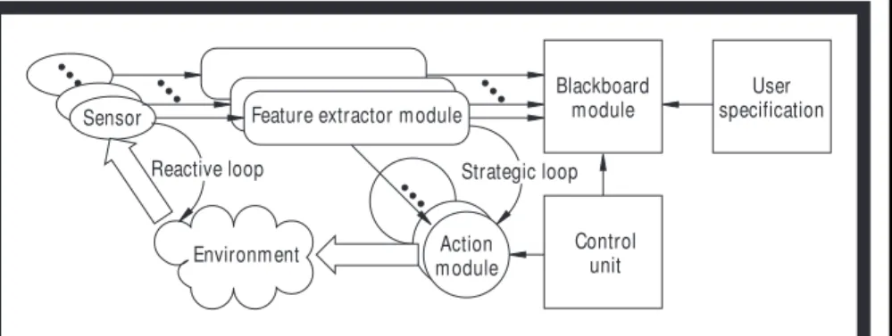
Figure 1 shows the overall system archi-tecture. This structure implements two lev-els of reasoning, one through the activities and the other through the blackboard. The thick arrow running from an action module to the environment represents a physical in-teraction with the environment, primarily by the motion of the robot. The thick arrow run-ning from the environment to the sensor rep-resents the gathering of information about Table 1. Comparison of classical control structures.
HIERARCHICAL BEHAVIORAL BLACKBOARD
Reactivity Medium High Medium
Intelligence Sequential Emergent Distributed
Global reasoning Yes No No
Multiple goals Yes Difficult Yes
Robustness Low High Medium
Reliability Low High Medium
Modularity Yes No Yes
Flexibility No No Yes
Expandability Yes Yes Yes
Adaptability No No Yes
Sensor integration Difficult Yes Yes
Environment Reactive loop
Sensor Feature extractor module
Blackboard module User specification Control unit Action module Strategic loop
the environment by the sensor. The system combines a central controller ensuring strate-gic reasoning and several activities in charge of low-level behaviors. The activities run concurrently, but only one activity action module directly commands the robot’s actu-ators. The blackboard control unit determines the activity that controls the robot, using its knowledge of the state of activities and user’s specifications. The control unit can also in-fluence the action module by specifying con-straints on its actions. For example, the pas-sageway activity, described in more detail later, is designed to avoid collisions with ob-stacles. The control unit can constrain it to try to maintain a certain direction of motion and a maximum speed.
An activity is an organizational unit that uses a basic skill to perform a specific func-tion—for example, following a person, pass-ing through a door, avoidpass-ing collision. Each activity includes sensors, one or more fea-ture extractor modules, and an action module necessary for it to carry out its task. To per-form reliably, the activity uses relevant sen-sors to focus on specific features of the environment.
The blackboard control unit monitors the environment and assesses the performance of enabled activities on the basis of infor-mation reported by the activity and its fea-ture extractor modules. The feafea-ture extrac-tor modules have two functions: filtering data to be passed to the blackboard control unit and focusing sensory perception on the ac-tion being performed. The feature extractor modules of disabled activities do not control the vehicle but rather monitor the environ-ment for possible conditions that their activ-ities could easily handle. For the vehicle to perform a complete task, it must combine the appropriate activities in the proper sequence, primarily driven by the events posted on the blackboard by the activities.
The blackboard system supports high-level symbolic decision making and central intelligent reasoning through the knowledge in the control unit. The only difference of our system from classical blackboard systems is that our activities do not use opportunistic problem solving but are sequenced and or-chestrated by the control unit to perform a global task in reaction to the changing environment.
Feature extractor module.Although a fea-ture extractor may depend on more than one sensor, it provides information on a specific
attribute in the environment. Sensors and their associated perception modules are con-tinuously operating. The feature extractor processes sensory data and expresses it in a suitable representation for the action or blackboard module.
The feature extractor expresses the rele-vant attributes of the environment symboli-cally and then relays them to the blackboard. Since the feature extractors are continuously operating, the blackboard reasoning module is instantly notified about the dynamic changes in the environment. Each feature ex-tractor is responsible for ensuring the con-sistency of the information it sends to the blackboard, relieving the blackboard of the time-consuming truth maintenance task.
Action module.During navigation, the en-abled action module determines the mobile robot’s direction and speed in response to in-formation acquired from the corresponding feature extractor. Therefore, low-level deci-sions are sensor-driven, ensuring tight, reac-tive control.
To intelligently guide real-time operation, the high-level reasoning module (that is, the blackboard module) provides the action module with the desired direction and speed based on its global understanding of the sit-uation. Nonetheless, it is the action module’s responsibility to provide the actual control signals and maneuver the mobile robot to meet the reasoning module’s recommenda-tions. The high-level commands may also in-clude constraints on the action modules’ op-erations to ensure smooth transition from one activity to another.
Blackboard module.The blackboard mod-ule, consisting of the blackboard and the blackboard control unit, assesses the robot’s global situation and provides sound decisions
about the appropriate action to meet user-specified goals safely. The blackboard con-trol unit performs this reasoning by process-ing symbolic information such as the sequence of specified goals, the current con-trol strategy, and the acquired knowledge of the states of the world and of the mobile robot. Symbolic and qualitative information about the features of interest are continuously posted by the feature extractors to the black-board.
Blackboard control unit. The blackboard control unit uses traditional forward-chain-ing production rules for the reasonforward-chain-ing process. The typical case involves the selec-tion of a suitable activity to satisfy a set of conditions derived from the goal require-ments or from the safety requirerequire-ments. The control unit’s role is to arbitrate between the different activities competing to take control of the mobile robot’s actuators.
The production rules activate or deactivate the appropriate activities according to the current state and the adopted control strat-egy. They may also modify certain operation parameters of the currently enabled activity. Since the activation-deactivation cycle is per-formed continuously in real time, this mod-ule appears to an external observer to be ex-plicitly commanding the mobile robot by smoothly switching to the appropriate activ-ities without interruption.
Blackboard essential states.The numeric-to-symbolic conversions are a challenge; we manage them mostly by means of the con-cept of essential states and events developed by Tigli et al.15(These conversions are a
mapping from numeric values to linguistic predicates.) To avoid overloading the black-board with information and to minimize the bandwidth requirement between modules, we limit the representation of the environ-ment’s state to symbolic attributes from the feature extractor modules and the vehicle’s state to symbolic information from the ac-tion modules. Generally, the decision-mak-ing process is sensitive only to coarse mea-sures of these attributes. For instance, the decision-making process would be interested in the fact that the mobile robot is close to a wall rather than the exact numeric distance. The essential states of any type of sensory data are defined by the partition of the nu-merical range of values of that sensory data into a small number of mutually disjoint par-titions. The boundaries between these
parti-F
OR THE VEHICLE TO PERFORM A
COMPLETE TASK
,
IT MUST
COMBINE THE APPROPRIATE
ACTIVITIES IN THE PROPER
SEQUENCE
,
PRIMARILY DRIVEN BY
THE EVENTS POSTED ON THE
BLACKBOARD BY THE ACTIVITIES
.
tions are chosen intuitively to facilitate sym-bolic reasoning. Similarly, the action mod-ules’ states can be expressed symbolically by nonoverlapping descriptions (for example, in the simplest case, “activated” or “deacti-vated”). The essential events are then defined as the changes in the corresponding essen-tial states. The essenessen-tial events cause the essential states to be modified on the blackboard.
The current state of the environment be-longs to the Cartesian product of the essen-tial states of all the sensory data. Similarly, the current states of all activities belong to the Cartesian product of all their essential states. These are represented by two vectors in the two Cartesian spaces illustrated in Fig-ure 2, which shows the sensory and action states that must be accounted for when defin-ing the rule set. We achieve completeness of the rule set by exploring and covering all the regions of the two Cartesian spaces, thus en-suring safe operation of the robot in reaction to changes in its environment. Besides these rules, there are also rules that decompose the user-specified goals into sequences of activ-ities that guide the robot.
Implemented activities
The activities we have implemented for the mobile-robot system include a passage-way activity, a floor anomaly activity, and a dynamic path-planning activity.
Passageway activity. The passageway ac-tivity’s main focus is navigating the vehicle toward open space. In effect it is a collision avoidance activity, except that one can spec-ify a desired direction, velocity, and destina-tion. The robot uses the activity for travers-ing through doorways, navigattravers-ing down hallways, and generally avoiding collision with any objects.
The passageway activity uses data from sonar range sensors to construct a two-di-mensional Cartesian grid representation of the robot’s environment. The histogram grid method16of representing this information
minimizes the effects of spurious data typi-cally produced by sonar range sensors. The computation of a grid cell’s value is based on the number of times an object has been de-tected in that cell; the larger the value, the more confidence that the cell is occupied. The activity then uses a sector elimination method to select a direction for collision-free
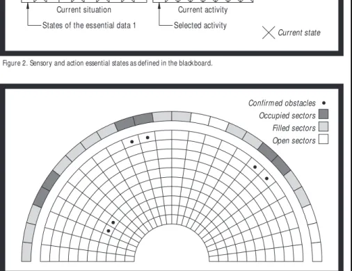
motion that most closely matches the desired direction. The sector elimination algorithm divides the sensed environment into 48 sec-tors covering a discoid centered about the robot, with a hole in the center, and extend-ing approximately 1 meter from the vehicle. Figure 3 shows the front half of a polar certainty grid and its associated sectors. Sec-tors with obstacles are marked in black and denoted as “occupied.” If the vehicle’s width is ignored, the sectors hashed out are suffi-cient to prevent a collision. In reality, the ve-hicle will collide with an object in a sector if commanded to move in the direction of an open sector next to that vector. This is pri-marily due to the lack of clearance between the object and the vehicle’s extremities. To account for this feature, we must increase the size of a group of “occupied” sectors. The figure shows these sectors in gray and de-notes them as “filled” sectors. Those sectors that are open for passage appear as white and are denoted as “open” sectors. The robot is steered toward the bisector of the open sec-tor that best matches the desired direction.
The essential-events information sent to the blackboard by the passageway activity’s feature extractor is not as precise as the
cer-tainty grid, but can be represented in the computer with less effort and memory. The open region around the vehicle is divided into four zones: “ahead,” “right,” “behind,” and “left.” The blackboard thus has a low-resolution view of the world in terms of quadrants around the perimeter. In addition to the data events posted by the feature ex-tractor the activity’s action module reports its status to the blackboard. The action’s only states are “enabled” or “disabled,” corre-sponding to whether or not the activity has control of the vehicle. In summary, the pas-sageway activity posts one data event con-sisting of four states and one status event consisting of two states.
Floor anomaly activity.The floor anomaly activity’s responsibility is to safely navigate the vehicle around or across anomalies, or obstacles, on the floor. Currently, work is under way on the development of a sensor and methodology, called FAD (Floor Anom-aly Detector) for object detection using a pair of Biris laser range finders.17 (The
compu-tation of range is based on a principle of re-placing the single iris in the camera with a couple of irises, hence its name, bi-iris.)
Confirmed obstacles Occupied sectors Filled sectors Open sectors
Figure 3. Sectors determined from sonar range data on a certainty grid.
Activities control Sensory data Activated Deactivated Current activity Selected activity Current situation
States of the essential data 1
Current state
The current floor anomaly activity deter-mines the feasibility of crossing obstacles such as channels or cables detected on the floor and takes the necessary actions to cross them safely. The activity’s feature extractor relies on available sensory information to identify any obstacles present in the vehicle’s vicinity. It extracts their relevant attributes (typically depth, width, orientation, and dis-tance from the vehicle), which control the ac-tion module. The acac-tion module guarantees a safe passage over the obstacle.
Essential events the floor anomaly activ-ity sends to the blackboard are a set of sym-bolic values describing the robot’s distance from the obstacle (“close” or “far”) and the robot’s direction in relation to the obstacle (“toward,” “parallel,” or “from”). We have determined most of the threshold values for these sets experimentally. The action mod-ule also reports its status to the blackboard, including “starting,” “orienting,” “proceed-ing,” “leav“proceed-ing,” “finish“proceed-ing,” and
“parallel-ing,” as well as the obvious “enabled” and “disabled.” Thus the floor anomaly activity posts two data events, one consisting of two states, the other of three; and two status events, one of two states and the other of six.
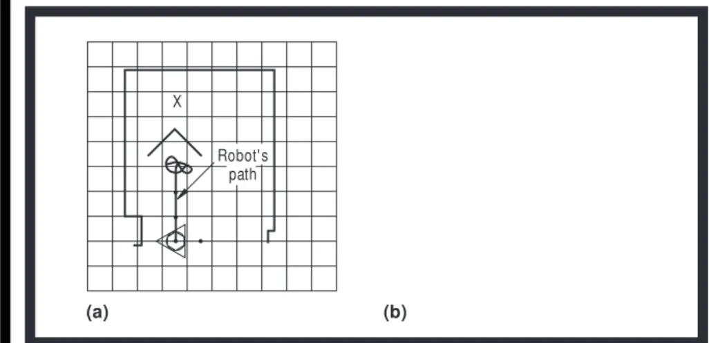
Dynamic path-planning activity. After sev-eral experiments with the passageway activ-ity, we discovered that under certain condi-tions the algorithm would not function satisfactorily. Collisions with objects were minimal, but the robot could easily be trapped in a corner as shown in Figure 4a.
The figure represents the robot by a com-bination of several shapes: a triangle, a circle, a hexagon, and a coordinate frame placed about the vehicle’s center point. The triangle represents the robot’s bumpers. The hexagon is the base of the robot. The circle represents the ring of sonar sensors around the base that are used by the passageway activity. The × marks the robot’s destination. The grid over-laid on the figure marks off areas of 1 square
meter, and the test zone is an approximately square area of 6 m ×6 m.
In contrast to the passageway activity, the dynamic path-planning activity can guide the robot around the partition, as shown in Fig-ure 4b, because it maintains a larger map of the robot’s environment, which it uses to de-termine possible paths to the robot’s desti-nation point. The gray-scale areas in Figure 4b represent certainty values for the exis-tence of objects detected by the robot’s sen-sor as it moves along its path. White indicates the highest likelihood that the cell is empty, black indicates the highest likelihood that the cell is occupied, and shades of gray indicate the various intermediate levels of likelihood of occupancy.
The path planner’s map is based on a his-togram grid map similar to the one used in the passageway activity, but it uses a rectan-gular grid centered about some point in the environment. The grid cells are 10 square cm; therefore, a map consists of 10,000 cells and takes approximately 100 ms to update. Range values for map creation come from a laser-based Biris camera and are more pre-cise and of higher angular resolution than those from the ultrasound sensors.
The path-planning algorithm is based on Warren’s modified A* algorithm,18extended
by Stuck19to account for the mobile robot’s
width. Similar to other planning algorithms, it takes much longer to compute a free path than the passageway activity (at times tak-ing 7 s compared to 100 ms for the passage-way activity), and therefore it is not as reli-able as the passageway activity. However, it maintains a much larger representation of the environment and uses a deterministic ap-proach to find a direction for the robot. Later in this article we will demonstrate how the path-planning activity can improve the robot’s performance.
Currently the path-planning activity does not communicate with the blackboard, so we cannot yet report on the essential states it will post on the blackboard. However, we think they will be similar to those generated by the passageway activity since the two activities have similar functions, differing primarily in approach.
System behavior ex ample
The following example of a mobile robot navigating across a typical factory floor demonstrates the performance goals that
mo-X
Robot's path
Figure 4. Mobile robot’s path: (a) passageway activity only; (b) passageway and path-planning activities.
(b) B A 3 4 5 6 7 I II III 1 0 2
Figure 5. Possible workshop scenario.
tivated our design of the activity-based blackboard architecture. We designed the passageway, path-planning, and floor anom-aly activities to address the kinds of prob-lems the robot encounters here.
In Figure 5, the robot is originally at loca-tion 0 and is required by the blackboard to navigate autonomously to destination point 7. The robot, perceiving no obstructions, pro-ceeds in the direction of point 7 until it reaches point 1, where the passageway ac-tivity notifies the blackboard of the presence of an obstacle. The passageway activity also realizes that the space between object II and the south wall is not wide enough for the robot to pass through, and, therefore, decides to seek an open space in another direction. The passageway activity can drive the mo-bile robot toward point 2, but due to limited storage capacity in the map used by the pas-sageway activity, objects sensed earlier are no longer available and the robot moves back toward point 1, driven by point 7.
The path-planning activity, with its greater knowledge of the environment, sug-gests to the blackboard an alternate route, which the passageway activity uses to guide the robot toward point 2. The robot reaches point 2, where the floor anomaly activity de-tects channel AB. The blackboard allows the floor anomaly activity to take over, tem-porarily, to maneuver the robot across this channel. The vehicle crosses the channel safely and proceeds along its temporary di-rection. If the floor anomaly acitivity had not been allowed to take over the robot, the path taken would have been the one shown
as a dashed line commencing from pont 2. This could have led to the wheels of the mo-bile robot having been trapped in the chan-nel. At point 3, the blackboard returns con-trol to the passageway activity after being notified by the floor anomaly activity of the successful completion of its task. Through-out this procedure, the path-planning activ-ity has been computing the paths that will get the mobile robot to its destination. One of these paths is from west to east between object I and object III. The blackboard real-izes that going through this passageway will bring the vehicle closer to the original goal point and commands the passageway activ-ity accordingly.
At point 4, the floor anomaly activity iden-tifies the second portion of channel AB, and the symbolic feature extractor notifies the blackboard that the robot can safely maneu-ver across it. The dashed line from point 4 towards object II identifies the path the robot would have taken if allowed to cross the channel at this point. However, the passage-way activity notifies the blackboard that there is no room for safe crossing of the chan-nel at this point because of the presence of object II on the other side. So the blackboard notifies the floor anomaly activity to go along the channel away from object II. At point 5 the blackboard allows the floor anom-aly activity to drive the robot across the chan-nel, and at point 6 the passageway activity drives the robot toward destination point 7. With these three activities guided and coor-dinated by the blackboard, the robot reaches its destination safely.
Implementation and
ex periments
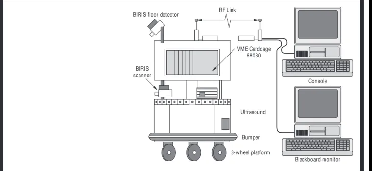
The mobile-robot system shown in Figure 6 implements the activity-based blackboard architecture. It consists of a Cybermotion platform fitted with a ring of 24 ultrasound sensors around the base, two Biris laser range finders for detecting floor anomalies, a scan-ning Biris laser range finder, and an odo-metric counter. An on-board Z80 processor serves as a PID (proportional-integral-de-rivative) controller for the mobile robot’s wheels and a counter for the odometer. All activities run on a 68030-based multipro-cessing platform that is embedded in the robot. During experimentation, we used up to seven processors, but made no attempt to optimize the loads on the processors. In gen-eral, one processor must be dedicated to each external device (ultrasound ring, Biris scan-ner, Biris FAD system, and mobile robot), freeing the rest for processing and interpret-ing the sensory data and communication to the blackboard.
The system is implemented primarily by means of tasks communicating through mes-sage passing on a multitasking computer platform. We guaranteed real-time perfor-mance by using a real-time multiprocessing operating system called Harmony, which al-lows the activity modules to be implemented across several processors, thus ensuring con-currency.
The decision-making mechanism is a rule-based production system using the BB_CLIPS blackboard system (developed
BIRIS floor detector RF Link
Console BIRIS scanner 3-wheel platform Blackboard monitor VME Cardcage 68030 Ultrasound Bumper
Figure 6. Photo of experimental mobile robot (a) and block diagram of robot’s configuration (b).
at the National Research Council’s Institute for Information Technology). It runs on a Macintosh IIfx and communicates with the activities via an RF modem. Since informa-tion posted on the blackboard is symbolic compact data and does not directly impact an activity’s performance, time delays usu-ally associated with using an RF modem are reduced. The only time this is a crucial fac-tor is when an activity wants control of the vehicle and the control unit is busy. In the current design of the blackboard, the con-trol unit does not perform extensive com-putations but releases this chore to other ac-tivities, so it is usually waiting to process
state changes that have been posted on the blackboard.
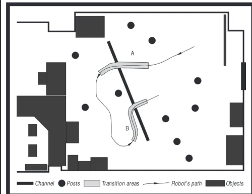
Passageway and floor anomaly experi-ment.The experiment diagrammed in Fig-ure 7 was designed to investigate the inter-action of the passageway and floor anomaly activities. The vehicle was commanded to navigate safely in the laboratory space, which was cluttered with stationary posts and other objects and some moving people. The laboratory also contained a simulated floor anomaly consisting of a channel of a known depth and size. During the experiment, the vehicle switched back and forth between the
two activities in response to information dy-namically posted on the blackboard.
In the default situation, the vehicle moved along a straight line segment (under pas-sageway activity control) until an object or a channel entered its visibility range and caused it to change its path. The feature ex-tractors assumed the responsibility of judg-ing objects and channels perceived by the sensors; they notified the blackboard only when these items constituted a significant obstruction. In cases when objects obstructed the vehicle’s intended path, the passageway action module decided on the corrective ac-tion with no intervenac-tion from the black-board. Such corrections appear in the figure as changes in the direction of the robot’s path. On the other hand, in cases of threatening channels, the blackboard commanded the floor anomaly activity to take over the vehi-cle’s control, until that activity reported suc-cessful crossing of the channel (section A in Figure 7). Figure 8 shows the BB_CLIPS rules triggered in this situation.
In cases when objects on the other side of the channel made it dangerous to cross, the blackboard commanded the floor anomaly ac-tivity to go parallel to the channel until the ve-hicle reached a safe crossing point. An exam-ple of this situation is shown as the section marked B in Figure 7. In this example the sys-tem control unit has a combined representa-tion of the objects and the channel on the floor. It is not possible to achieve this type of per-formance using a single activity because each activity is tuned to handle a certain type of condition. The BB_CLIPS rules triggered for this situation are shown in Figure 9. Robot's path B A Transition areas Posts Channel Objects
Figure 7. An experiment using the passageway and floor anomaly activities.
( d e f r u l e Co mma n d _ f l o o r _ a n o ma l y _ c r o s s _ 0 " "
( CHANNEL_ EXTRACTOR ( ma n e u v e r TRUE) ( c l o s e r TRUE) ( p a r a l l e l ? p a r a l l e l ) ) ( OPEN_ SPACE_ EXTRACTOR ( c l e a r FALSE) ( r i g h t ? r i g h t ) ( l e f t ? l e f t ) ) ( FLOOR_ ANOMALY_ ACTI ON_ MODULE_ ( s t a t e PROCEEDI NG) )
Figure 9. BB_ CLIPS rules for moving parallel to channel.
( d e f r u l e Co mma n d _ f l o o r _ a n o ma l y _ c r o s s _ 0 " "
( CHANNEL_ EXTRACTOR ( ma n e u v e r TRUE) ( c l o s e r TRUE) ( p a r a l l e l ? p a r a l l e l ) ) ( OPEN_ SPACE_ EXTRACTOR ( c l e a r TRUE) ( r i g h t ? r i g h t ) ( l e f t ? l e f t ) )
( FLOOR_ ANOMALY_ ACTI ON_ MODULE_ ( s t a t e ? f l o o r _ a n o ma l y _ s t a t e &~PARALLELI NG) ) ( COMMAND ? c o mma n d &~" f l o o r _ a n o ma l y _ p a r a l l e l " )
( COMMAND ? c o mma n d &~" f l o o r _ a n o ma l y _ c r o s s " ) =>
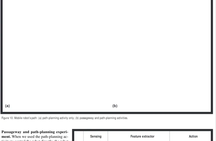
Passageway and path-planning experi-ment.When we used the path-planning ac-tivity to control the robot directly, the robot sometimes collided with an object, as shown in Figure 10a. Such collisions were caused primarily by delays in computing a new path. For this reason, the path-planning activity is not reactive enough to be effective and reli-able unless the robot’s speed is very slow.
The passageway and path-planning activ-ities are complementary because they have identical action modules. When combined, they increase the robot’s chances of safely reaching its destination. In Figure 10b, the passageway activity drove the robot away from the wall and prevented the collision shown in Figure 10a. In this experiment, the path-planning activity directly interacted with the passageway activity by using a com-mon action module, as shown in Figure 11, and was not interfaced through the black-board.
In the configuration shown in Figure 11, the path-planning activity’s feature extractor module sends the passageway action mod-ule the desired direction of motion. The pas-sageway activity’s feature extractor module sends the passageway action module an open-sector direction. The passageway ac-tivity uses the two directions to compute an actual direction for the mobile robot.
This experiment demonstrates how the two activities complement one another. By working together, they minimize the need to
use the blackboard to transfer data between activities and reduce the amount of trivial in-formation on the blackboard. In this limited example, the two activities are more com-plementary than conflicting and thus func-tion together rather well. In the case of the passageway and floor anomaly activities, however, each performs substantially differ-ent functions.
Summary of experimental results. We have yet to integrate all three activities into
one system. Results from the combined floor anomaly and passageway activities support the claim that our architecture is suitable for reactive and strategic control of a mobile ve-hicle. Results from the path-planning activ-ity combined with the passageway activactiv-ity support the idea that certain activities are complementary and will function well to-gether, bypassing the blackboard as a com-munication medium.
Nevertheless, we believe the blackboard is necessary for maintaining a global per-Figure 10. Mobile robot’s path: (a) path-planning activity only; (b) passageway and path-planning activities.
Environment Modified A* path planning using rectangular grid Laser range finder Ultrasound ring Sector elimination using polar histogram grid Open sector direction Desired direction Sensing Ranges
Feature extractor Action
Passageway activity Passageway action Path-planning activity Ranges
Figure 11. Interaction of passageway and path-planning activities. The large arrows signify an interaction with the en-vironment by the robot and a sensing of the enen-vironment by the Ultrasound ring and laser range finder.
spective of the mobile robot’s state and also for supervising the activities. For example, the path planner computes an optimal path for the robot. If the robot must wait for an el-evator door to open, the blackboard’s control unit can override communications between the path planner and the passageway activ-ity, stopping the vehicle and resuming its op-eration after the door opens.
The blackboard also allows the system to monitor an activity’s performance and re-place that activity with one with better per-formance. If for any reason the passageway activity fails, the system can use the path-planning activity to drive the mobile robot safely, provided the robot’s operating speed is reduced.
Our two experiments show that this ar-chitecture is suitable for experimental ro-botics applications, particularly because of its flexibility and modularity. It allowed us to experiment with several activities and in-vestigate their interactions, while some components were implemented and others were simulated. It also allowed us to com-bine two activities to achieve higher perfor-mance.
System evaluation
Earlier, we discussed a number of desir-able behavior and design attributes of a mo-bile robot. Although expressing them quan-titatively is difficult, we can summarize qualitatively how the activity-based black-board architecture meets these requirements.
Behavior attributes
• Reactivity: The control architecture’s re-activity is ensured by the conceptual sep-aration of two types of decision making: strategic and tactical. The system demon-strated its reactivity by switching the con-trol context, but not the concon-trol level, in response to dynamic and unexpected events.
• Intelligence: Defining intelligence as the ability to cope with new or trying situa-tions, we have been able to demonstrate that the mobile robot can cope with un-known environment configurations. Using the blackboard as the high-level decision-making mechanism, we incor-porate progressive levels of situation un-derstanding by including rules to describe those situations.
• Global reasoning: The robot performs global reasoning primarily through the control unit and the blackboard. Arbitra-tion between competing activities is ac-complished by a set of rules that allows the most appropriate activity to take control of the mobile robot and resolves informa-tion conflicts. For example, as we saw in Figure 7, at the appearance of an object across the channel, the control unit com-manded the floor anomaly activity to go parallel to the channel before crossing it.
• Multiple-goal resolution: Each activity’s control algorithm is exposed to continu-ous information coming from the corre-sponding feature extractor. Therefore, each action module has its own
sugges-tions as to the control signals to be sent to the vehicle actuators. The blackboard, however, performs selective activation and deactivation of the action packages, arbitrating the multiple goals provided by the different activities. The blackboard continuously assesses the relevance and applicability of each activity to the situ-ation at hand.
• Robustness: More testing must be per-formed, and activities added, before we can comment accurately about the mobile robot’s robustness. Activities with similar functions (for example, the path-planning and passageway activities) can improve robustness.
• Reliability: A significantly long time is required to build confidence in any sys-tem’s reliability, and we have not yet tested all the system’s components thor-oughly. So far, we have extensively tested the passageway activity, and it performs consistently (does not allow the robot to collide with objects detected by the sen-sor) in many different scenarios. The
ad-dition of the path-planning activity im-proved the system’s reliability to reach a destination.
Design attributes
• Modularity: The simple interconnections of the activities’ components allow inde-pendent design of the modules before they are integrated to form a complete ac-tivity. For example, the feature extractor of the floor anomaly activity was devel-oped and tested independently from the action module of the same activity. Sim-ilarly, at a higher granularity level, the ac-tivities were developed separately from the blackboard system. The architecture’s modularity facilitated both design and de-bugging.
• Flexibility: The interconnection patterns of the control framework’s components impose no restrictions on the information exchanged by the modules. There are no limitations on the messages coming from the feature extractors. Therefore, we changed the symbolic information gen-erated by the feature extractors, especially that of the passageway activity, several times during the experimentation, to im-prove the blackboard’s decision-making capability. These changes were totally transparent to the system architecture and organization. This system flexibility al-lowed design decisions to be based on ex-perimental evidence and practical per-formance measures.
• Expandability: The system’s modularity facilitates its expansion. For example, de-velopers worked separately on skill-achieving activities, before these activi-ties were integrated into the control structure. The modifications to the con-trol architecture were limited to the addi-tion of appropriate rules in the blackboard control unit to take advantage of the added capabilities.
• Adaptability: The high-level blackboard control over the activities continuously changes the system’s focus of attention in response to changing world configu-rations. The blackboard chooses the ac-tivity that can handle the situation best: the floor anomaly activity in the vicinity of threatening channels and the passage-way activity the rest of the time. The blackboard rules include implicit knowl-edge of the capabilities of both activities’ action modules.
T
HE BLACKBOARD ALSO
ALLOW S T HE SYST EM T O
MONIT OR AN ACT IVIT Y
’
S
PERFORMANCE AND
REPLACE T HAT ACT IVIT Y
W IT H ONE W IT H BET T ER
PERFORMANCE
.
• Multisensor integration: The vehicle has four different sensors: (1) the on-board odometer, (2) the ultrasound transducers, (3) the pair of Biris laser ranging cameras for anomaly detection, and (4) the scan-ning Biris laser ranging camera. Although we have not yet integrated all the activi-ties into one system, the architecture has accommodated several of these sensors during the experiments.
W
E STILL HAVE MANY ISSUESto address in developing our robotic archi-tecture. In particular, there is no rigorous method for converting some of the numeric data from the feature extractors into symbolic data for the blackboard. In our case, these conversions followed the idea of essential events and states, which minimizes the amount of data going to the blackboard, but we have not tested this concept thoroughly. The advantage of essential events and states is mainly the reduction of data, which, in turn, allows us to address the serious prob-lem of the rule base’s completeness. As the number of activities increases, the possible combination of events increases exponen-tially, leading to a combinatorial explosion. The solution is that not all activities should report all the time. For example, the floor anomaly activity should post on the black-board information about a floor anomaly only when one has been detected.
On the practical side, to fully exploit the benefits of this type of design, we must have access to a clean multitasking operating tem. Unfortunately, many mobile-robot sys-tems are closed syssys-tems, designed as black boxes rather than potential programming de-velopment workstations, making experi-mental research difficult. A mobile robot’s environment is so dynamic and difficult to constrain that an efficient and easily modifi-able development system is essential. The system must be easily reprogrammed and re-configured for the different environments it may encounter. Thus, it is imperative to sim-plify the creation of activities and their inte-gration into the system.
Finally, the design of special-purpose ac-tivities allows us to create specific functions that a mobile robot can perform reliably. These activities give the appearance of robot intelligence, but only in a limited domain. We believe that to achieve more intelligent
behavior, a supervisory centralized module like the blackboard is necessary, but it is not necessary that all communications go through the blackboard. We have had some success with this approach, but to fully ex-ploit it, we must develop more activities.
Acknow ledgments
This work was partially supported by a Natural Sciences and Engineering Research Council grant to Gerald Karam, who kindly used it to support Reda Fayek as a master’s student at Carleton Uni-versity. We thank Marie-Claude Thomas, at Sophia Antipolis University in Nice, France, for financial and supervisory support of Jean-Yves Tigli. This work was performed in cooperation with the Pre-carn ARK (Autonomous Robot for a Known En-vironment) Project, which receives its funding from Precarn Associates Inc., the Department of Industry Science and Technology Canada, the Na-tional Research Council of Canada (NRC no. 38355), Technology Ontario, and Ontario Hydro.
References
1. D.W. Payton, “An Architecture for Reflexive Autonomous Vehicle Control,” Proc. IEEE
Int’l Conf. Robotics and Automation, IEEE Computer Society Press, Los Alamitos, Calif., 1986, pp. 1838–1845.
2. C. Malcolm, T. Smithers, and J. Hallam, “An Emerging Paradigm in Robot Architecture,” in Intelligent Autonomous Systems 2, Vol. 2, T. Kanade, F.C.A. Groen, and L.O. Hertzberger, eds., Elsevier Science Publish-ers, Amsterdam, Dec. 1989, pp. 545–564 3. J.S. Albus, R. Lumia, and H. McCain,
“Hier-archical Control of Intelligent Machines Ap-plied to Space Station Telerobot,” Proc. IEEE
Symp. Intelligent Control, IEEE CS Press, 1987, pp. 20–27.
4. R. Lumia, “Using Nasrem for Real-Time Sen-sory Interactive Robot Control,” Robotica, Vol. 12, No. 2, March 1994, pp. 127–135. 5. C. Isik and A.M. Meystel, “Pilot Level of a
Hierarchical Controller for an Unmanned Mobile Robot,” IEEE J. Robotics and
Au-tomation, Vol. 4, No. 3, June 1988, pp. 241–255.
6. R. Hinkel, T. Knieriemen, and E. von Put-tkamer, “An Application for a Distributed Computer Architecture—Real-Time Data Processing in an Autonomous Mobile Robot,”
Proc. Eighth Int’l Conf. Distributed Comput-ing Systems, IEEE CS Press, 1988, pp. 410–417.
7. R.C. Arkin, “Motor Schema-Based Mobile Robot Navigation,” Int’l J. Robotics
Re-search, Vol. 8, No. 4, Aug. 1989, pp. 92–112.
8. A. Stentz, “The Codger System for Mobile Robot Navigation,” in Vision and Navigation,
The Carnegie Mellon Navlab, Charles E. Thorpe, ed., Kluwer Int’l Series in Engineer-ing and Computer Science, Kluwer Acade-mic Publishers, Boston, 1990, chap. 9, pp. 187–201.
9. Y. Goto and A. Stentz, “The CMU System for Mobile Robot Navigation,” Proc. Third Int’l
Conf. Robotics and Automation, IEEE CS Press, 1987, pp. 99–105.
10. R.A. Brooks, “A Layered Intelligent Control System for a Mobile Robot,” Third Int’l
Symp. Robotics Research, MIT Press, Cam-bridge, Mass., 1985, pp. 365–372. 11. R.A. Brooks, “A Robust Layered Control
System for a Mobile Robot,” IEEE J.
Robot-ics and Automation, Vol. RA-2, No. 1, Mar. 1986, pp. 14–23.
12. B. Hayes-Roth and M. Hewett, “BB1: An Implementation of the Blackboard Control Architecture,” in Blackboard Systems, R. Engelmore and T. Morgan, eds., Addison-Wesley, Reading, Mass., 1988, chap. 14, pp. 297–313.
13. R.E. Fayek, R. Liscano, and G. Karam, “A System Architecture for a Mobile Robot Based on Activities and a Blackboard Con-trol Unit,” Proc. IEEE Int’l Conf. Robotics
and Automation, IEEE CS Press, 1993, pp. 267–274.
14. S.Y. Harmon, “Practical Implementation of Autonomous Systems: Problems and Solu-tions,” Proc. Int’l Conf. Intelligent
Au-tonomous Systems, Elsevier, Amsterdam, 1986, pp. 47–59.
15. J.-Y. Tigli et al., “Methodology and Comput-ing Model for a Reactive Mobile Robot Con-troller,” Proc. IEEE Int’l Conf. Systems, Man,
and Cybernetics, IEEE Press, New York, 1993, pp. 17–20.
16. A. Manz, R. Liscano, and D. Green, “A Com-parison of Real-Time Obstacle Avoidance Methods for Mobile Robots,” Proc. Second
Int’l Symp. Experimental Robotics, Springer Verlag, London, 1991, pp. 301–316. 17. A. Manz et al., “Floor Obstacle Avoidance for
a Mobile Robot,” Proc. 1993 DND Workshop
on Advanced Technologies in Knowledge Based Systems and Robotics, Industrie Canada, Ottawa, Canada, 1993.
18. C.W. Warren, “Fast Path Planning Using Modified A* Method,” Proc. IEEE Int’l Conf.
Robotics and Automation, IEEE CS Press, 1993, pp. 662–667.
19. E.R. Stuck et al., “Map Updating and Path Planning for Real-Time Mobile Robot Navi-gation,” Proc. IEEE/RSJ/GI Int’l Conf.
Intel-ligent Robots and Systems, Munich, IEEE Press, New York, 1994, pp. 753–760.
Ramiro Liscanois a research officer at the Insti-tute for Information Technology at Canada’s Na-tional Research Council. His research interests have been in the processing of sensory data, pri-marily for real-time, autonomous navigation of mobile robots. He is also pursing his PhD at the PAMI Laboratory in the Systems Design Engi-neering Department of the University of Waterloo, Canada. His thesis research is in the development of reasoning techniques for the interpretation of sensory data from 3D active vision systems for modeling indoor environments. He graduated from the University of New Brunswick, Canada, in me-chanical engineering in 1982, and earned his MS (1984) in mechanical engineering from the Uni-versity of Rhode Island, specializing in robotics and computer vision. He is a member of the IEEE. He can be reached at the Institute for Information Technology, National Research Council, Ottawa, Ontario K1A 0R6, Canada; [email protected].
Allan Manz currently works as a robotics engi-neer at Applied Robotics in Saskatoon, Sas-katchewan, where he is investigating the au-tonomous navigation of underground mining vehicles. His research interests are in the process-ing of sensory data from ultrasound, 3D active vi-sion, and 2D passive systems, primarily for
au-tonomous navigation of mobile robots. He com-pleted his bachelors (1986), post graduate diploma (1989), and MS (1993) degrees from the Univer-sity of Saskatchewan in mechanical engineering. He can be reached at the Institute for Information Technology, National Research Council, Ottawa, Ontario K1A 0R6, Canada; [email protected],
Elizabeth R. Stuckis currently a research asso-ciate at the institute for information technology at Canada’s National Research Council. Her research interests are in human-computer interaction, in particular the visualization and manipulation of computer information. She graduated from St. John’s College with a degree in liberal arts and earned her MS (1987) and PhD (1992) in com-puter science from the University of Minnesota with an emphasis in artificial intelligence and a minor in cognitive science. She is a member of AAAI and ACM. She can be reached at the Insti-tute for Information Technology, National Re-search Council, Ottawa, Ontario K1A 0R6, Canada; [email protected].
Reda E. Fayek is a PhD candidate at the PAMI Laboratory in the Systems Design Engineering
Department of the University of Waterloo, Canada. His research focus on the use of 3D computer vi-sion and active sensing techniques in 3D modeling and mapping of natural terrain and outdoor au-tonomous navigation. He graduated with a degree in electrical and computer engineering in 1988 from Ain-Shams University, Egypt, and earned his MEng in systems and computer engineering in 1992 from Carleton University. He is a member of the IEEE. He can be reached at Systems Design Engineering Department, University of Waterloo, Waterloo, Ontario N2L 3G1, Canada; [email protected].
Jean-Yves Tigliis a member of the I3S Labora-tory, pursuing his PhD, at the Nice-Sophia An-tipolis University. His research interests are in knowledge-based situated and behavioral agent systems for controlling mobile robotics, and also miniature mobile robots. He received a degree in computational engineering from the Nice-Sophia Antipolis University, France, in 1991. He is mem-ber of the IEEE, Robotics & Automation, and Man and Cybernetics societies. He can be reached at Laboratoire I3S - CNRS URA 1376, Université de Nice, Sophia Antipolis, Valbone 06560, France; [email protected].