HAL Id: hal-02482414
https://hal.archives-ouvertes.fr/hal-02482414
Submitted on 18 Feb 2020HAL is a multi-disciplinary open access archive for the deposit and dissemination of sci-entific research documents, whether they are pub-lished or not. The documents may come from teaching and research institutions in France or abroad, or from public or private research centers.
L’archive ouverte pluridisciplinaire HAL, est destinée au dépôt et à la diffusion de documents scientifiques de niveau recherche, publiés ou non, émanant des établissements d’enseignement et de recherche français ou étrangers, des laboratoires publics ou privés.
Broadband UHF RFID Tag Antenna for Bio-Monitoring
Daniel Marques, Matthieu Egels, Philippe Pannier
To cite this version:
Daniel Marques, Matthieu Egels, Philippe Pannier. Broadband UHF RFID Tag Antenna for Bio-Monitoring. Progress In Electromagnetics Research B, EMW Publishing, 2016, 67, pp.31 - 44. �hal-02482414�
Broadband UHF RFID Tag Antenna for Bio-Monitoring
Daniel Marques*, Matthieu Egels, and Philippe Pannier
Abstract—This paper presents the design and fabrication of a broadband UHF RFID tag for bio-monitoring applications. The proposed tag is realized with a thin FR4 substrate of 200 µm, which can be considered as flexible. It shows good performances both in free space and placed on human body. For instance, in free space, the tag can be read at 14 m in the UHF RFID band and at an average distance of 4.6 m when it is placed on the human body. The overall tag size is only 80 mm× 50 mm × 200 µm.
1. INTRODUCTION
RFID technology continues to evolve and expands its areas of activity. One recent application is for medical staff to control the patient health using harvested vital parameters [1–3].
However, this field of study requests fabrication constraints as the size reduction of the tag or the use of flexible and biocompatible materials to be ergonomic and acceptable for the patient. The tag also need to be low cost in case of daily renewals. Moreover, the tag antenna faces high permittivity and high losses properties of the human body which affect the impedance matching, the radiation pattern and the reading distance of the tag in the UHF RFID band [4].
Many tag antennas have been studied when placed on-body for bio-monitoring and person tracking applications. In [5], Santiago et al. present two antennas (using Rogers RT5880 as substrate) for this kind of use. The first one is composed of two quarter-wavelength patches connected to a ground plane. The second one has a similar design but slots are added in order to make the impedance matching easier. Simulations are performed on free space and with a human-body model. Results show the stability of the impedance between the two simulations. However reading distances are not explicit. In [9] the same design is presented. However, unlike the earlier antenna, this one is flexible. A reading distance of 3.5 m is obtained in the FCC Band [902 MHz–928 MHz]. In [6] a loop antenna coupled to an inductive loop is proposed. This tag has a reading distance varying from 2.7 m to 5.7 m. Depending on its placement on the human body, with a minimal distance from the body of 2 mm during measurements. Marrocco et al. present four H-slot antennas in [7, 8, 10, 11]. They are realized in different substrates as silicone, EPDM (ethylene-propylene-diene monomer) and felt. Three of them use a ground plane. The best antenna has a reading distance of 4.5 m in the ETSI Band [865.6 MHz–867.6 MHz]. Articles about implanted tags [12] can be found, but they only permit reading distances of a few centimeters. Alternatives exist using active tags [1], but they are more expensive than passive tags.
All the previous presented antennas have substrates with thicknesses higher than 1 mm. Some of them use a ground plane in order to increase the tag performances. These techniques employed to minimize the influence of the human body make the tags more expensive and too conspicuous for the patient. Therefore, the conception of small antennas able to minimize the human body influence without reducing the reading distance while staying low profile and low cost is a challenge for UHF RFID passive tags.
Received 1 February 2016, Accepted 26 March 2016, Scheduled 6 April 2016
* Corresponding author: Daniel Marques ([email protected]).
The authors are with the Institut Materiaux Microelectronique Nanosciences de Provence, UMR CNRS 7334, Aix-Marseille Universite, 5 rue Enrico Fermi, Batiment Neel, Technopole de Chateau Gombert, 13453 Marseille Cedex 13, France.
In this paper, a broadband antenna able to minimize the influence of impedance mismatch is proposed. It reaches a minimal reading distance of 3 m in the ETSI Band and has both low cost and low profile. The antenna is matched with the Alien Higgs 4 chip [13]. The paper is divided in four sections as follows. Section 2 presents the human forearm model implemented on ANSYS HFSS v.14 used to simulate the tag on the human body. Dimensions and dielectric properties of tissues composing a forearm are detailed. Section 3 focuses on the design rules (Sub-section 3.1), with simulations and measurement results of the broadband antenna both in free space (3.2) and on-body (3.3). Section 4 presents the conclusions and the perspectives.
2. HUMAN ARM MODEL
A model of human forearm has been realized on ANSYS HFSS from the applet “The Visible Human Project” [14]. This applet allows the visualization of 2D tomographic images by intersecting a 3D tomography and a plane having any desired position and orientation. Thanks to this, a tomographic image of a human forearm can be extracted to obtain thicknesses and diameters of different tissues composing the forearm, as shown in Figure 1. From this image, the skin and fat have respectively an average thickness of 2 mm and 1 mm. Muscles form an irregular cylinder with an average diameter of 67 mm, and the two bones, ulna and radius, have respectively 14 mm and 15 mm of diameter.
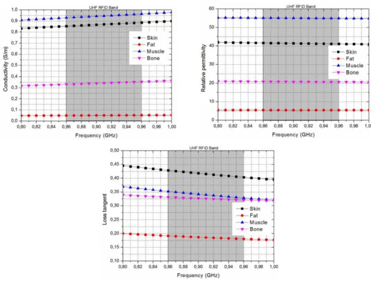
The variation of relative permittivities, dielectric losses and conductivities of tissues depending upon frequency are shown in Figure 2 extracted from [15]. Dielectric features of tissues should be assumed as constant in the UHF RFID Band (gray part of the graphs of Figure 2). Thus, these parameters are considered to be constant recalled in Table 1.
These values confirm the high dielectric features of the human body. In addition, human tissues have high loss characteristics which attenuate the electromagnetic wave magnitude and consequently reduce the reading distance in the UHF RFID band [4]. Plus, they are conductors. Implying a surface current distribution over a tissue area during the tag reading as shown in Figure 3 (with the model of the skin). The appearance of surface current around the antenna which causes radiation distortions impacting the radiation of the antenna.
The impedance of the antenna is simulated when placed on the human forearm model. During
Figure 1. Tomographic image of a human forearm.
Table 1. Dielectric features of human tissues at 867 MHz [15].
Tissue Skin Fat Muscle Bone Relative Permittivity εr 41.5 5.47 55.1 20.8
Dielectric loss tan(δ) 0.43 0.19 0.35 0.33 Conductivity σ (S/m) 0.86 0.05 0.93 0.33
Figure 2. Variation of conductivity, relative permittivity and dielectric loss.
Figure 3. Surface current distribution over the skin.
Figure 4. Human forearm model on HFSS.
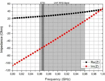
these simulations, different parameters of human tissues, as the relative permittivity, loss tangent and depth, are varied in order to anticipate the differences due to the morphology unique to each individual in measurements. We choose to present only the parameters with a major influence on the impedance of the antenna (Figure 5).
Figure 5. Simulated impedance and impact of the variation of parameters of the human tissues.
Results show that variations of dielectric and physical parameters of human tissues have an impact on the impedance of the antenna. We have also observed that the parameter with the highest effect is the tissues depth which varies considerably from one individual to another.
Thus, one solution to overcome these variations involves the use of a broadband antenna. Design rules of this type of antenna will be explained in the Section 3.1.
3. BROADBAND ANTENNA DESIGN
Once placed on human body, the antenna suffers a frequency shift. In order to minimize it, it has been decided to realize a broadband antenna whose impedance matches to the chip (Alien Higgs 4 [13]) on a wide frequency band. The substrate is FR4 (εr = 4.2; tan δ = 0.02) with a thickness of 200 µm in
order to be able to conform it on the forearm. The dimensions of the tag are 80 mm× 50 mm, which are slightly smaller than those of a credit card. The copper lines have a thickness of 18 µm. The matching between the antenna and the chip is first made in the free space, then it is compared with the impedance matching when placed on a human body.
3.1. Design Rules
The maximum power transfer from the antenna to the chip is obtained when the reflection coefficient Γ∗ is the lowest. Equation (1) gives the expression of this parameter. It is considered a good matching between the antenna and the chip when|Γ∗|dB is less than −10 dB.
Γ∗= Zant− Z
∗
chip
Zant+ Zchip
(1) The proposed broadband antenna is based on a dipole with a length of 2λ0. The design is based
on two steps:
• Design of a half-wave folded dipole antenna and the use of a “T-Match” for impedance matching
in the ETSI band.
• Increase of the length of the antenna to reach 2λ0 and use of folded strands to charge the dipole
to increase the frequency bandwidth.
For the first step, a half-wave dipole antenna is realized. At 867 MHz, the theoretical length corresponds to λ/2 = 173 mm, λ being the free-space wavelength. The relative permittivity of the substrate is not considered because its thickness is too low and negligible in the free space. The length of the antenna is too important for the available dimensions of the substrate. Therefore the antenna is folded. Figure 6 depicts the folding technique.
Figure 6. Evolution from half-wave dipole to folded half-wave dipole.
Figure 7. Impedance of the half-wave folded dipole without the matching network.
Figure 9. Equivalent circuit of “T-Match” [17].
Figure 10. Variation of the reflection coefficient depending on Lstub.
Figure 11. Antenna impedance and chip conjugate impedance; reflection coefficient.
The impedance matching technique “T-Match” [16] was chosen to improve the reactance, shown in Figure 7, of the half-wave folded dipole. The new antenna and the equivalent circuit of the matching network are shown respectively in Figures 8 and 9.
Its dimensions are modified to improve return loss. For instance, Figure 10 depicts the evolution of the reflection coefficient depending on the length Lstub of the matching network. It shows that the
matching between the antenna and the chip is sensitive to variations of the length Lstub. A variation
of +/− 1 mm of is enough to mismatch the antenna. For a good matching Lstub = 14.4 mm is chosen.
Figure 11 shows the impedance of the antenna compared to the conjugate impedance of the chip as well as the reflection coefficient. It also highlights that the frequency bandwidth of the antenna does not cover the entire UHF RFID Band, with a specification of Γ <−10 dB. It is only matched in the ETSI Band. With these improvements, the total length of the antenna is now of 157 mm, which is lower than the half wavelength.
The second step is to increase the frequency bandwidth of the antenna using remaining disponible area of the tag. The idea is to use parasitic dipoles [18] which are excited by coupling effects with the main radiator element. However, this solution depends on the dimensions of parasitic dipoles and the gap between them in order to obtain in-phase surfacic currents. Generally, the gap between two elements corresponds to the quarter of the wavelength (i.e., 86 mm). In this case, the maximum gap is
Figure 12. Surface current distribution for three different lengths of dipoles.
Figure 13. Current distribution and radiation pattern of the half-wave dipole on HFSS.
Figure 14. Current distribution and radiation pattern of the full-wavelength dipole on HFSS.
Figure 15. Current distribution on a folded dipole with a length of 2λ0.
Figure 16. Current distribution and radiation pattern of the dipole of length 2λ0 on HFSS.
Figure 17. Simulated impedance and reflection coefficient for half-wave and 2λ0 dipoles.
fixed to 50 mm which leads to coupling effects would inducing inverted currents on the parasitic dipoles, degrading the performances of the tag antenna. The distribution of the surface current depending on the length of the dipole is studied. Figure 12 represents this distribution through three lengths of dipoles.
The simulations results presented in Figure 13 confirm the theory depicted in Figure 12 for a half-wave dipole. The radiation pattern is isotropic on the H-plane (XZ) and contains two lobes in the
E-plane (Y Z) matching a half-wave dipole radiation pattern. Now, according to Figure 12, considering
a full-wavelength dipole, the folding of this antenna will bring the sum of currents with opposite phases. Figure 14 shows the surface current distribution for the folded full-wavelength dipole and gives evidence of this phenomenon: the radiation pattern is modified and not corresponding to that of a dipole. Moreover, the gain is reduced.
Finally, by choosing an antenna with a length of 2λ0, it is possible to sum the currents of the
unfolded strands with those of the folded strands as shown in Figure 15. The simulation results depicted in Figure 15 confirm this theory. Figure 16 shows that currents on the straight strands are in phase with currents on the folded strands. In order to keep a dipole with a length of 2λ0 in an area of
80 mm× 50 mm, the folded strands are meandered. The total length of the dipole is 667.7 mm which is less than 2λ0= 692 mm because the resonant frequency has to be higher to match the antenna with the
chip. The radiation pattern corresponds to that of a dipole. Moreover the gain has increased of 0.1 dB. As shown in Figure 17, the frequency bandwidth has increased from 37 MHz to 120 MHz.
3.2. Free-Space Simulations and Measurements
3.2.1. Reflection Coefficient
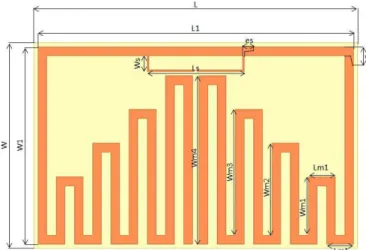
First, simulations and measurements are realized in free space. The matching between the antenna and the chip, as detailed in Section 3.1, is performed in free space. It does not take into account the forearm in order to compare the reading distances and the frequency shift between simulations and measurements in two configurations: in free space and on the forearm. Figure 18 depicts the chosen dimensions of the antenna matched to operate in free space in the UHF RFID band and Figure 19 shows the prototype.
Impedance measurements are performed in an anechoic chamber using the protocol proposed by [19]. Simulation and measurement results are compared in Figure 20.
Results show a frequency shift of 20 MHz carried out to ward lower frequencies. However, the antenna stays correctly matched in the ETSI band due to his frequency bandwidth of 120 MHz.
Figure 18. Dimensions of the tag.
Figure 19. Prototype.
Figure 20. Impedance and reflection coefficient of the broadband antenna on free space.
3.2.2. Reading Distance
The test bench is a RFID test system developed by National Instruments (NI-100) [20]. It allows to test and measure the performance of RFID devices. The bench is used as an emulated reader in order to measure the maximum reading distance of the tag in free space. It uses two linearly polarized antennas. One is the transmitting antenna, and the other is the receiving antenna. Measurements are made in an
Figure 21. Simulated and measured reading distances.
anechoic chamber. The measured reading distance is shown in Figure 21 and given for a reader power of 3.2WEIRP.
We can see a frequency shift to ward lower frequencies between simulated and measured reading distances. This result confirms the frequency shift observed for the measured reflection coefficient. In the ETSI band, the broadband tag has a reading distance of 14 m instead of 15.5 m obtained in simulations. The tag presents good performances for the ETSI band in free space.
3.3. On-Body Simulations and Measurements
The interest of designing a flexible antenna having a low quality factor is to compensate frequency shifts due to the establishing of the antenna on a material with a relative permittivity which differs from 1 and varies considerably from one person to another. In this case, the broadband tag antenna faces a strong variation of the relative permittivity because it is placed on the human body whose dielectric properties are presented in Figure 2. Thus, we realize simulations with the forearm model, detailed in Section 2 of this article, in order to anticipate measurement results. Figure 22 depicts the orientation of the tag on the forearm and the reflection coefficient simulation result in this position.
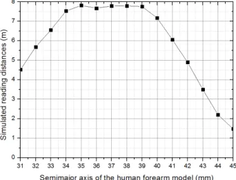
Despite its large frequency bandwidth, simulation results show an important frequency shift to ward lower frequencies. The reflected power is reduced to−8 dB in the ETSI band. Thus the antenna is considered to be matched in this band. The simulated reflection coefficient is given for the human forearm model with the normalized parameters seen on Section 2. To anticipate the differences which can be found in measurements due to the differences of morphology between individuals, we simulate the reading distances depending on the antenna curvature radius (Figure 23). This parameter is dependent on the semimajor axis (model of Figure 22) of the human forearm model which is the only parameter modified for this simulation. When the semimajor axis is increased, the curvature radius is reduced and vice versa. As we can see for a semimajor axis varying between 31 mm to 45 mm, the reading distance varies between 1.5 m to 7.8 m. Thus, the antenna curvature radius has an important impact on the performance of the tag.
In order to evaluate the reading distance of the tag, measurement has been performed with the NI bench on ten different persons. One of the applications of this tag concerns the heart rate monitoring. Therefore, the tag is placed on the wrist as shown in Figure 24. Reading distances are depicted in Figure 25. Measurements made on males are marked (M), and those on females are marked (F). Blue lines correspond to the objective fixed for the project for which the tag is realized.
It appears that results differ from one person to another. This can be due to different morphologies
Figure 23. Simulated reading distances depend-ing on the semimajor axis of the human forearm model.
Figure 25. Measured readings distances on several people.
Figure 26. Simulation and maximum, minimum and average measurement results of the reading distance when comparing 10 subjects.
Table 2. Comparison between the different designs.
Ref. Volume Reading Range Figure of Merit
[6] 3508 mm3 5.7 m 16 [9] 8352 mm3 3.5 m 4.2 [10] 4725 mm3 4 m 8.5 [11] 18900 mm3 4.5 m 2.4 [21] 5400 mm3 3 m 5.5 Proposed tag 800 mm3 4.6 m [2 m–9 m] 57.5 [25–112.5]
that could cause more or less frequency shifts and losses. An FR4 substrate with 200 µm thickness is not well adapted to the wrist morphology, provoking a gap between the tag and the forearm and thus increasing the reading distance. On the other hand, a bad polarization alignment among the tag, the transmitting and receiving antenna can reduce the reading distance. All these measurement inaccuracies can be responsible for the results variability. In order to judge tag performances in terms of reading distances, maximum, minimum, average and simulation results obtained in the band [800 MHz; 1 GHz] are compared in Figure 26.
In the UHF RFID band, simulation results are higher than the average reading distances measured. In the ETSI band, 4.6 m of average reading distance is obtained with a maximum reading distance of 9 m.
4. CONCLUSION
The flexible tag presented in this article has a reading distance of 14 m in free space in the ETSI band. Its bandwidth of 120 MHz permits to cover all the UHF RFID band. Once placed on the human body, its average reading distance is about 4.6 m in the ETSI band. Moreover, measurement results show a reading distance varying between 2 m and 9 m depending on the morphology of the person on whom the tag is placed. These performances are proven satisfying to be used in bio-monitoring applications as shown in Table 1. This table compares the figure of merit between tags of the state of art and the proposed tag. The figure of merit is the ratio of reading range to volume occupied by the tag. As we can see, the figure of merit of the proposed tag is higher than those of references. The major contributor to this performance is the low volume of the proposed tag compared to the others.
REFERENCES
1. Cangialosi, A., J. E. Monaly, and S. C. Yang, “Leveraging RFID in hospitals: Patient life cycle and mobility perspectives,” IEEE Applications and Practice, 18–23, Sep. 2007.
2. Bouet, M. and G. Pujolle, “RFID in eHealth systems: Applications, challenges and perspectives,”
Annals of Telecommunications, Vol. 65, No. 9–10, 497–503, Oct. 2010.
3. Yang, L., L. J. Martin, D. Staiculescu, C. P. Wong, and M. M. Tentzeris, “Conformal magnetic composite RFID for wearable RF and bio-monitoring applications,” IEEE Transactions on
Microwave Theory and Techniques, Vol. 56, No. 12, 3223–3230, Nov. 2008.
4. Lin, M.-H. and C.-W. Chiu, “Human-body effects on the design of card-type UHF RFID tag antennas,” IEEE International Symposium on Antennas and Propagation, 521–524, Jul. 2011. 5. Santiago, A. G., C. A. Fernandes, and J. R. Costa, “Broadband UHF RFID passive tag antenna
for near-body operation,” IEEE International Conference on RFID-Technologies and Applications
(RFID-TA), 271–274, 2012.
6. Tsai, M. C., C. W. Chiu, H. C. Wang, and T. F. Wu, “Inductively coupled loop antenna design for UHF RFID on-body applications,” Progress In Electromagnetics Research, Vol. 143, 315–330, 2013.
7. Occhiuzzi, C., S. Cippitelli, and G. Marrocco, “Modeling, design and experimentation of wearable RFID sensor tag,” IEEE International Transactions on Antennas and Propagation, Vol. 58, 2490– 2498, Aug. 2010.
8. Marrocco, G., “Body-matched RFID antennas for wireless biometry,” Proceedings EuCAP 2006 , Nice, France, Nov. 2006.
9. Rajagopalan, H. and Y. Rahmat-Samii, “Conformal RFID antenna design suitable for human monitoring and metallic platforms,” Proceedings of the 4th European Conference on Antennas and
Propagation, 1–5, Apr. 2010.
10. Manzari, S., S. Pettinari, and G. Marrocco, “Miniaturized and tunable wearable RFID tag for body-centric applications,” IEEE International Conference on RFID-Technologies and Applications
(RFID-TA), 239–243, 2012.
11. Manzari, S., C. Occhiuzzi, and G. Marrocco, “Reading range of wearable textile RFID tags in real configurations,” Proceedings of the 5th European Conference on Antennas and Propagation, 433–436, 2011.
12. Occhiuzzi, C., M. Simiele, R. Lodato, and G. Marrocco, “Feasibility, limitations and potentiality of UHF RFID passive implants,” IEEE International Conference on RFID-Technologies and
Applications (RFID-TA), 40–45, 2012.
13. Alien Higgs 4, www.alientechnology.com/products/ic/higgs-4/. 14. Visible Human Server, visiblehuman.epfl.ch.
15. “Dielectric properties of body tissues,” niremf.ifac.cnr.it/tisspro/.
16. Marrocco, G., “The art of UHF RFID antenna design: Impedance-matching and size-reduction techniques,” IEEE Antennas and Propagation Magazine, Vol. 50, No. 1, Feb. 2008.
17. Alarcon, J., R. Saba, M. Egels, and P. Pannier, “A flexible UHF RFID tag for harsh environments,”
IEEE International Conference on RFID-Technologies and Applications (RFID-TA), 2012.
18. Balanis, C. A., Antenna Theory: Analysis and Design, 2nd Edition, John Wiley and Son, 1997. 19. Qing, X., C. K. Goh, and Z. N. Chen, “Impedance characterization of RFID tag antennas and
application in tag co-design,” IEEE Transactions on Microwave Theory and Techniques, Vol. 57, No. 5, 1268–1274, May 2009.
20. “National instruments RFID measurements,” www.ni.com/tutorial/6645/en/.
21. Dubok, A. and A. B. Smolders, “Miniturization of robust UHF RFID antennas for use on perishable goods and human bodies,” IEEE Antennas and Wireless Propagation Letters, Vol. 13, 1321–1324, 2014.