HAL Id: lirmm-01275607
https://hal-lirmm.ccsd.cnrs.fr/lirmm-01275607
Submitted on 20 Sep 2018
HAL is a multi-disciplinary open access
archive for the deposit and dissemination of
sci-entific research documents, whether they are
pub-lished or not. The documents may come from
teaching and research institutions in France or
abroad, or from public or private research centers.
L’archive ouverte pluridisciplinaire HAL, est
destinée au dépôt et à la diffusion de documents
scientifiques de niveau recherche, publiés ou non,
émanant des établissements d’enseignement et de
recherche français ou étrangers, des laboratoires
publics ou privés.
Experiments on a variable stiffness tensegrity
mechanism for an MR-compatible needle holder
Quentin Boehler, Anastasios Zompas, Salih Abdelaziz, Marc Vedrines,
Philippe Poignet, Pierre Renaud
To cite this version:
Quentin Boehler, Anastasios Zompas, Salih Abdelaziz, Marc Vedrines, Philippe Poignet, et al..
Ex-periments on a variable stiffness tensegrity mechanism for an MR-compatible needle holder. CRAS:
Computer/Robot Assisted Surgery, Sep 2015, Bruxelles, Belgium. �lirmm-01275607�
Experiments on a variable stiffness tensegrity
mechanism for an MR-compatible needle holder
Quentin Boehler
ICube CNRS - University of Strasbourg Email: [email protected]Anastasios Zompas
LIRMM CNRS - University of Montpellier Email: [email protected]Salih Abdelaziz
LIRMM CNRS - University of Montpellier Email: [email protected]Marc Vedrines
ICube CNRS - University of Strasbourg Email: [email protected]Philippe Poignet
LIRMM CNRS - University of Montpellier Email: [email protected]Pierre Renaud
ICube CNRS - University of Strasbourg Email: [email protected]Abstract—In this paper, we present the design of a novel MR-compatible needle holder with variable stiffness and a first experimental evaluation of its ability to be controlled in position and stiffness. The device should be able to control both the orientation and the angular stiffness of the needle around the insertion point within the MR-environment. To do so, our design is based on tensegrity mechanisms, a class of prestressed mechanisms that exhibit interesting properties for our context since they are compact, lightweight and remotely controllable. An experimental setup is developed. The position and stiffness control on one degree of freedom is then performed using an open loop control strategy. Encouraging results are finally presented as well as future works to be carried out.
I. INTRODUCTION
In interventional radiology, MR imaging is of great inter-est for percutaneous procedures. Radiologists have however to handle the lack of space in the MR scanner and conse-quently a very limited accessibility to the patient. A number of robotic devices has therefore been proposed [1] to help them in different needle insertion tasks. Robotic assistance for abdominal procedures on the liver or the kidney has interestingly received less attention [2], [3]. The design of a robotic device in this context is indeed challenging. First, it is required to develop a compact device with a large workspace. Needle orientation can in particular be in the order of ±45◦with respect to the normal to the skin. Second, liver and kidney present significant physiological motions, due to the breathing influence. Needle grasping cannot be stiff and constant throughout the breathing cycle, or it leads to organ lacerations [4]. One simple approach is to grasp the needle during its insertion, and then release it to minimize tissue damage [2]. The repetition of grasp-release cycles during a procedure can however increase the risk of needle grasping failure.
We have introduced in [5] an alternate approach, where the position and stiffness of the robotic needle holder can be controlled. When insertion accuracy is required, stiffness is maximized and the needle can be inserted. When organ laceration has to be avoided, the device stiffness is lowered. The efficiency of the approach is obviously dependent on the ability to design and control such a device, in particular with low stiffness levels to be compatible with tissue properties.
An original architecture based on tensegrity mechanisms has been introduced in that purpose. In this paper, we present the current design of the needle holder, and show the first experimental evaluation of the ability to modify with tensegrities the orientation and stiffness of a needle guidance system.
II. NEEDLE HOLDER DESIGN
The device we propose is based on three main observa-tions. First, task analysis with radiologists shows that the needle orientation control is the most difficult part of needle guidance. The needle holder is therefore designed as a 2 degrees of freedom (DOF) mechanism with two rotations. Second, tissue cleansing around the needle insertion point is mandatory, as well as a preliminary skin incision, before needle insertion. No element can be placed at the insertion location, which means a remote center of motion (RCM) mechanism has to be designed. Third, MR compatibility of the device actuation can be ensured by using remote actuation with cable transmission [6]. Bowden cables are particularly adapted, since cables can be tensioned without applying any forces on the patient. This actuation principle is hence considered in the device design.
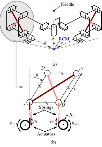
The needle holder we propose from this analysis is rep-resented in Fig. 1(a). It is composed of two planar linkages, each one providing one DOF, connected by a cylindrical joint so that the device exhibits a RCM. As shown in Fig. 1(b), each linkage is a parallelogram-based mechanism that is actuated by two cables in series with springs. In this way, a remote actuation can be performed. More importantly, each linkage constitutes a tensegrity mechanism. It is a self-stressed system composed of compressed bars and tensioned springs, as defined in [7]. This is of particular interest, because the two actuators used for each linkage enable us to control the linkage position and its stiffness: the config-uration θ of the linkage (Fig. 1(b)) and the corresponding angular stiffness can be modified by changing the lengths (ρ1, ρ2). The device is finally actuated by four actuators to control the two DOF and the two angular stiffnesses.
The dimensional synthesis of the device was performed to ensure ±45◦rotations with respect to the vertical direction.
Needle RCM θ ρ2 (a) (b) A B C D ~x ~z ~y L ρ1 Actuators Springs θm1 θm2 Rp
Figure 1. (a) RCM-based needle holder architecture, (b) Planar tensegrity mechanism based on parallelogram linkage.
The parallelogram bars are of equal length L =70 mm. This tends to show the device can be a compact solution. The absence of active elements in the needle holder itself is interesting to ensure MR compatibility and a limited weight to be patient-mounted. The angular stiffness can be adjusted through the spring prestresses. A zero stiffness behavior should be reachable using zero free length springs as introduced in [8]. With standard linear springs, a stiffness variation of 25 % can be expected from simulation. With custom non-linear springs, a 300% variation can be obtained.
III. EXPERIMENTAL EVALUATION
The fundamental aspect in the device is its ability to mod-ify the needle orientation and its stiffness. As a consequence, the experimental evaluation aims at validating the desired range of motion, and analyzing the mechanism ability to modify the stiffness level as well. The proposed device is composed of two identical decoupled planar mechanisms. The experiments are therefore performed, without loss of generality, on one parallelogram linkage.
A. Experimental setup
The planar tensegrity mechanism is designed to be pro-duced using additive manufacturing with polymer materials. Shafts are made out of brass and polymer bushings are em-ployed. In this way, the device structure is MR compatible. The whole experimental setup is depicted in Fig. 2 and 3. In this version, two DC actuators (Harmonic Drive RH-5A) are used to drive directly the cables through pulleys.
Actuator Load cell Cable Spring Planar tensegrity mechanism
Figure 2. Experimental setup.
Optical encoder Torquemeter
A B
D C
Figure 3. Instruments of the planar tensegrity mechanism.
Standard linear springs of stiffness 0.27 N/mm are integrated along the cables. For sake of evaluation, load cells (Scaime K1107, 50 N) are added between the springs and the actuators. A torquemeter (Fig. 3, Scaime DR1, 1 N.m) is also integrated in one of the parallelogram joints (A, Fig 1(b)) to estimate the mechanism stiffness. An optical encoder (Fig. 3, HP HEDS-5540) is finally mounted on the revolute joint located in the jointB (Fig. 1(b)) to measure the current angle θ. Both the torquemeter and the optical encoder are non-MR compatible but used for validation experiments only.
B. Control
In a first approach to evaluate the system performance, we use the control strategy depicted in Fig. 4. The con-figuration θ of the parallelogram and the angular stiffness Kθ are here controlled in open loop. The reference lengths ρ∗= (ρ∗
1, ρ∗2) are computed using the Inverse Static Model (ISM) of the system. They are related to the actuator states θm = (θm1, θm2) through the pulley radius Rp (see Fig. 1(b)). The static model relates the configurationθ and the stiffness Kθ of the system to the actuator states. It is valid under quasi-static conditions. Its analytic expression is obtained by minimizing the elastic energy stored in the springs with respect to the angle θ for known external
ISM Rp θ∗ K∗ θ ρ∗ θ∗ m + − PID Actuators u θm
Figure 4. Control loop.
wrench, so that the structure is in equilibrium. The actuators are then controlled using a PID controller that generates a torque signalu on the actuators inputs.
C. Results
The system is evaluated through two experiments to validate the workspace and assess the stiffness variation feasibility.
1) Workspace validation: The workspace is explored while the stiffness reference K∗
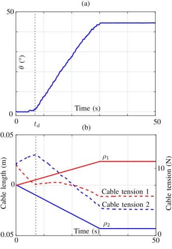
θ is set to 1 N.m/rad. To do so, we impose the reference angle θ∗ to follow a linear trajectory between 0 and 45° in 30 s. The trajectory was chosen to be slow and smooth enough to remain under quasi-static conditions. The zero value ofρ is set after a calibration phase during which the cables are prestressed at 10 N while the mechanism is maintained in the configuration θ = 0°. Results are depicted on Fig. 5.
Time (s) Time (s) C ab le le n g th (m ) C ab le te n si o n (N ) (a) (b) ρ1 ρ2 Cable tension 1 Cable tension 2 0 -0.05 0.05 0 50 50 0 0 10 0 50 θ (° ) td
Figure 5. Experimental results of the workspace validation. (a) Evolution of θ. (b) Evolution of the cable lengths(ρ1, ρ2) and the cable tensions.
Table I
EXPERIMENTAL RESULTS ON THE STIFFNESS VARIATION
Cables prestress (N) 7.5 10 12.5 Kθat θ1= 10° (N.m/rad) 1.03 0.84 0.66
Kθat θ1= 30° (N.m/rad) 1.06 0.82 0.63
The full angular range can be explored using the open loop control strategy as seen on Fig. 5(a). Some noise on the angle measurement appears, that is due to a digital to analog conversion of the encoder value for acquisition. It however remains below the encoder resolution. One can notice a delay on[0, td] s during which the angle remains at a steady state while the lengths ρ are being modified. It can be mostly explained by static friction located at the mechanism joints regardless of the system prestress. This effect clearly appears on the cable tensions during this phase, where the cable 2 is tensioned and the cable 1 released until the parallelogram is moving. The 45° angle can however be reached in 30 s with a nonlinearity in the trajectory due to friction.
2) Stiffness variation assessment: The stiffness variation using different levels of prestress is then assessed. First the system is calibrated at θ = 0° to set the correct level of prestress. Then, the parallelogram is set to a configurationθ1. In this configuration, a perturbation torque δT is applied in joint A (Fig. 1(b)) through the torquemeter (Fig. 3) so that the parallelogram is deflected with an angular variation δθ. The angular stiffness Kθ is estimated with the relation δT /δθ, ensuring that δθ remains small, here less than 3°. Measures are repeated for two angles along the mechanism workspace (10 and 30°) and for three levels of prestress.
Results are shown in table I. As predicted by the ISM, the angular stiffness of the mechanism can be lowered by increasing the prestress in the cables. This remains true all along the workspace. Stiffness variation up to 35 and 40% could be obtained in the configurations θ1 =10° and 30° respectively. This variation could even be enlarged to 50% when considering a 5 N prestress in θ1= 10°.
IV. CONCLUSIONS AND DISCUSSION
This paper showed the firsts steps toward an MR com-patible needle holder with position and stiffness control. Encouraging results are obtained on the feasibility of the approach with the use of tensegrities. Further works will now be carried on the position control in closed loop to deal with the static friction effect. The development of nonlinear springs to increase the stiffness variation range has been assessed in [9] and will be then integrated to the existing setup for further evaluation.
ACKNOWLEDGMENT
This work was supported by French state funds man-aged by the ANR within the Investissements d’Avenir pro-gramme (Robotex 10-EQPX-44, Labex CAMI - ANR-11-LABX-0004) and by the Région Alsace and Aviesan France Life Imaging infrastructure.
REFERENCES
[1] H. Elhawary, Z. T. H. Tse, A. Hamed, M. Rea, B. L. Davies, and M. U. Lamperth, “The case for MR-compatible robotics: a review of the state of the art,” The international journal of medical robotics and computer
assisted surgery, vol. 4, no. 2, pp. 105–113, 2008.
[2] O. Piccin, N. Kumar, L. Meylheuc, L. Barbé, and B. Bayle, “Design, development and preliminary assessment of grasping devices for robo-tized medical applications,” in ASME 2012 IDETC/CIE, 2012, pp. 65– 73.
[3] I. Bricault, N. Zemiti, E. Jouniaux, C. Fouard, E. Taillant, F. Dorandeu, and P. Cinquin, “Light puncture robot for CT and MRI interventions,”
Engineering in Medicine and Biology Magazine, IEEE, vol. 27, no. 3, pp. 42–50, May 2008.
[4] D. Sun, C. Willingham, A. Durrani, P. King, K. Cleary, and B. Wood, “A novel end-effector design for robotics in image-guided needle procedures,” Int J Med Robot., vol. 2, no. 1, pp. 91–97, 2006.
[5] Q. Boehler, M. Vedrines, S. Abdelaziz, P. Poignet, and P. Renaud, “Toward an MR-compatible needle holder with adaptive compliance using an active tensegrity mechanism,” in Surgetica 2014, Dec. 2014. [6] S. Abdelaziz, L. Esteveny, P. Renaud, B. Bayle, L. Barbé, M. De Math-elin, and A. Gangi, “Design considerations for a novel MRI compatible manipulator for prostate cryoablation,” International journal of
com-puter assisted radiology and surgery, vol. 6, no. 6, pp. 811–819, 2011. [7] R. Motro, Tensegrity: Structural Systems for the Future.
Butterworth-Heinemann, Jun. 2003.
[8] J. L. Herder, “Energy-free systems: theory, conception, and design of statically balanced spring mechanisms,” Ph.D. dissertation, Nov. 2001. [9] Q. Boehler, M. Vedrines, S. Abdelaziz, P. Poignet, and P. Renaud, “Par-allel singularities for the design of softening springs using compliant mechanisms,” in ASME 2015 IDETC/CIE.