Publisher’s version / Version de l'éditeur:
Vous avez des questions? Nous pouvons vous aider. Pour communiquer directement avec un auteur, consultez la première page de la revue dans laquelle son article a été publié afin de trouver ses coordonnées. Si vous n’arrivez pas à les repérer, communiquez avec nous à PublicationsArchive-ArchivesPublications@nrc-cnrc.gc.ca.
Questions? Contact the NRC Publications Archive team at
PublicationsArchive-ArchivesPublications@nrc-cnrc.gc.ca. If you wish to email the authors directly, please see the first page of the publication for their contact information.
https://publications-cnrc.canada.ca/fra/droits
L’accès à ce site Web et l’utilisation de son contenu sont assujettis aux conditions présentées dans le site
LISEZ CES CONDITIONS ATTENTIVEMENT AVANT D’UTILISER CE SITE WEB.
Canadian Building Digest, 1972-05
READ THESE TERMS AND CONDITIONS CAREFULLY BEFORE USING THIS WEBSITE. https://nrc-publications.canada.ca/eng/copyright
NRC Publications Archive Record / Notice des Archives des publications du CNRC :
https://nrc-publications.canada.ca/eng/view/object/?id=dc537ce8-ca46-46ab-8f4b-722c1bfc536a
https://publications-cnrc.canada.ca/fra/voir/objet/?id=dc537ce8-ca46-46ab-8f4b-722c1bfc536a
NRC Publications Archive
Archives des publications du CNRC
For the publisher’s version, please access the DOI link below./ Pour consulter la version de l’éditeur, utilisez le lien DOI ci-dessous.
https://doi.org/10.4224/40000773
Access and use of this website and the material on it are subject to the Terms and Conditions set forth at
Thermal resistance of building insulation
Canadian Building Digest
Division of Building Research, National Research Council Canada
CBD 149
Thermal Resistance of Building
Insulation
Originally published May 1972 C. J. ShirtliffePlease note
This publication is a part of a discontinued series and is archived here as an historical reference. Readers should consult design and regulatory experts for guidance on the applicability of the information to current construction practice.
There are daily reminders that every effort should be made to conserve energy, not only because of rising costs but also because of the need to control air pollution. Increased use of insulation to reduce the energy requirements of buildings is one way to achieve these ends. If designers are to design insulation systems and select appropriate materials. however. they should have a clear understanding of how insulation works. This Digest is designed to provide some of the information required for a better understanding of insulation as a material.
Resistance Concept
The rate at which heat flows through a slab of material under steady-state conditions may be expressed by
Q = A( T)/R
where A is the area of the face through which heat flows:
T is the difference between the temperatures of the warm and cold faces of the material; R is the thermal resistance per unit area of the piece of material.
The value of the thermal resistance of a piece of material can be thought of as the temperature difference across it required to produce one unit of heat flow per unit area. In the British system of units T is expressed in degrees Fahrenheit, Q in Btu per hour, and A in square feet; the units for R are degrees F per Btu per hour per square foot.
In the building field "insulation" is generally understood to mean a material that provides more than one unit of resistance per inch of thickness. Most materials sold as building insulation provide between 2 and 6 units per inch.
Thermal Resistance of Air Spaces
Heat is transferred across an air space by conduction. or by a combination of conduction and convection, and by radiation. Heat transfer by conduction is independent of orientation, but it is inversely proportional to thickness. That by convection, on the other hand, is highly dependent on both orientation and thickness (Figure 1) and on the height of the enclosure. Heat transfer
by radiation is independent of both thickness and orientation of the air space but dependent on the reflectivity of the enclosing surfaces (Figure 1). All three mechanisms are dependent on the temperatures of the surfaces. When the three heat transfer processes occur at the same time, the over-all thermal resistance of air spaces, both reflective and non-reflective, becomes practically independent of thickness for thicknesses over about 1 inch (Figure 2).
Figure 1. Variation of heat transfer across air spaces with thickness, orientation, surface reflectivity and fibre fill showing size contribution by radiation, conduction and pure convection.
Figure 2. Resistance versus thickness for air spaces and wood.
The resistance of a thick air space can be increased by sub-dividing it into several thin layers. The resistance of the whole space is then the sum of the resistances of the thin air spaces plus the resistances of the separators. This approach is most effective when the material used to subdivide the space has a low emissivity, as with aluminum foil. In this case the heat transfer by radiation is reduced to less than 10 per cent of what it would be if the separator were ordinary kraft paper. It is important to remember, however, that foil by itself does not provide thermal resistance; foil facing an air space increases the resistance of the air space. The magnitude of this effect is shown by the curves in Figure 2 for air spaces with high and low emissivity surfaces. The increase in resistance achieved by sub-dividing will be reduced if any air is allowed to move from one space to another or if the reflective surface becomes coated with dirt or condensation.
Commercial insulations generally have two basic structures: a continuous body of gas that contains a dispersion of solid particles or fibres; and a continuous matrix of solid material with a random dispersion of gas-filled cavities.
When a small amount of opaque solid material is distributed throughout an air space, it inhibits heat transfer by convection and radiation while contributing little to conduction, thereby raising the value of the thermal resistance of the space (Figure 1). Solids such as glass, rock and plastic that provide little resistance to heat flow can be used in this way to produce good insulation. The limiting value for a low density, open pore type of insulation is given by the uppermost curve in Figure 2, which represents an ideal situation of heat transfer through air by conduction only. The lowest curve represents the other extreme, inasmuch as it includes the full effect of radiation and convection. Low density, open pore insulations have resistance versus thickness curves that lie somewhere between these extremes.
The closed pore type of insulation can have gases other than air in the cells and thus can have resistances higher than are possible for air-filled materials. Figure 3 shows conduction-only curves for refrigerant gas R11, in this case Freon-11, and a mixture of this gas and air; both are well above the pure air curve. It also shows the curve for one type of newly foamed urethane with cells filled with R11. Although this curve is below the R11 curve, it is above the upper limit for low density, open pore type insulation. The curve of resistance versus material thickness will depend on the interaction of the heat transfer processes in the material. It may be a straight line or a more complex curve. The structure and composition of the material and the test conditions will largely determine the shape.
Figure 3. Resistance versus thickness for materials, standard test conditions. Aging Effects
When there is gas other than air in the cells, it attempts to escape through the cell walls by diffusion. Similarly, air and water vapour try to diffuse into the cell spaces from outside. The various diffusion processes proceed independently of each other and at quite different rates. Gases with large molecules such as Freon-11 and -12 may take years to diffuse out of a high quality urethane foam, but carbon dioxide can diffuse out of the same foam in only a few days and air may diffuse into the cells in a matter of weeks. Times will be much shorter at higher temperatures.
The amount of thermal resistance provided by a gas mixture in the cells changes, with time, until equilibrium is achieved. Consequently, the thermal resistance of insulation will vary as the material ages. The fully aged value of resistance should be used for calculating extremes of
temperature or condensation of water vapour for buildings expected to have a life span of many decades. Open cell insulations contain only air and are not subject to this aging effect. Enclosing urethane in an impermeable skin such as aluminium foil or metal facings prevents diffusion of gases in either direction. Polyethylene-coated kraft pair, wax coatings or a dense skin of urethane formed during foaming will similarly reduce the rate of diffusion. If the processes that cause aging of urethane are thereby reduced to negligible rates, the initial high value of thermal resistance, 7 to 9 units per inch, can be used for design calculations.
Effect of Density on Thermal Resistance
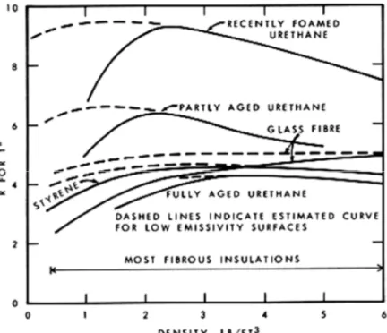
The resistance of all types of insulation is strongly dependent on the amount of solid material present, especially at the low densities that are of practical interest. Figure 4 shows how the resistance of 1-inch-thick layers of different materials, measured under a set of standardized test conditions, varies with density. At very low densities there is so little solid material that there is an appreciable amount of heat transfer through the sample by radiation and some by convection as well. As the proportion of solid material is increased, these components of heat transfer become quite small until at some point the increased conduction due to increased amount of solid just matches the reduction due to decreased convection and radiation. This is the density for maximum resistance. Beyond this point resistance decreases slowly as the amount of solid increases.
Figure 4. Resistance of 1-inch specimens versus density.
Reflective surfaces facing and in contact with insulation can be used to increase the resistance of low density insulations. If the bounding surfaces of an insulation have a low emissivity, there will be less heat transfer by radiation and over-all resistance will be less dependent on density. The dotted curves in Figure 4 are examples of the results for samples with aluminum foil at the surface.
The cost of insulation is dependent on density. Manufacturers tend to market insulations at densities lower than those that give maximum R per unit thickness because lower densities give a lower cost per unit of resistance. The range in which most commercial fibrous insulations are produced is shown in Figure 4.
The curves in Figures 2 to 4 apply for a particular mean temperature. Building insulations may have to operate in environments ranging from below -50 to over 200°F. The components of heat flow in a material will change accordingly, with the largest single effect resulting from change in thermal resistance of the air or refrigerant gas.
As temperature increases, the resistance of gases with heat transfer only by conduction decreases. For example, a 1-inch air space at -50°F has a resistance of about 7; at 150°F it has a resistance of about 5. The resistance of air-filled insulations follows the same pattern; the resistance of glass fibre insulation varies from about 6.5 at -50°F to about 4 at 150°F. The resistance of newly foamed urethane decreases with increasing temperature above 50°F and with decreasing temperature below 50°F. This is due to condensation of the refrigerant gas within the closed cells, and can reduce the resistance below that of a less costly, air-filled insulation.
Resistance Values For Designing
For most types of insulation resistance values at room temperature may be found in handbooks, technical literature, and manufacturer's product sheets and technical brochures. The variation of thermal resistance with the parameters mentioned above are not covered as thoroughly and are probably available only in reference books on insulation, in technical literature, and in manufacturers' technical brochures.
In non-critical designs it may be adequate to compare and select insulation on the basis of a single value of thermal resistance at a mean temperature that may not even be in the operating range. Careful designs, or designs that are meant to minimize the amount of insulation required or to use the most economical thickness of insulation, should take into account all factors that affect thermal resistance. This is particularly true for insulations containing gases other than air. The occurrence of condensation of the gas can reduce the resistance to below that for a less costly, air-filled insulation.
Care must be taken in the design to ensure that the insulation will be protected from air pressure differences that could cause a flow of air through the insulation and from water and water vapour that could wet the material, all of which reduce the thermal resistance of the insulation. Previous Digests on walls and roofs deal with the problems of placement of insulation in various building systems and should be referred to for further information.
Formed-in-Place Insulations
Spray-on, foamed-in-place, and blown insulations may be the only practical materials for insulating hard-to-get-at locations. The properties of such insulations are very dependent on the conditions that exist during application, on the nature of the installation, and on the skill of the applicator. These materials should not be expected to have as high a resistance as similar materials produced under factory conditions.
Conclusion
Because resistance of insulation depends on so many variables the designer should ensure that the products he recommends are applicable under the anticipated conditions of use. Information not usually found in the manufacturer's literature is contained in the Guide and Data Books and the Handbook of Fundamentals published by the American Society for Heating, Refrigerating and Air-Conditioning Engineers.