HAL Id: hal-01804149
https://hal.archives-ouvertes.fr/hal-01804149
Submitted on 31 May 2018HAL is a multi-disciplinary open access archive for the deposit and dissemination of sci-entific research documents, whether they are pub-lished or not. The documents may come from teaching and research institutions in France or abroad, or from public or private research centers.
L’archive ouverte pluridisciplinaire HAL, est destinée au dépôt et à la diffusion de documents scientifiques de niveau recherche, publiés ou non, émanant des établissements d’enseignement et de recherche français ou étrangers, des laboratoires publics ou privés.
Polychromatic Light
Mushegh Rafayelyan, Etienne Brasselet
To cite this version:
Mushegh Rafayelyan, Etienne Brasselet. Spin-to-Orbital Angular Momentum Mapping of Poly-chromatic Light. Physical Review Letters, American Physical Society, 2018, 120 (21), pp.213903. �10.1103/PhysRevLett.120.213903�. �hal-01804149�
Spin-to-Orbital Angular Momentum Mapping of Polychromatic Light
Mushegh Rafayelyan and Etienne Brasselet*
Univ. Bordeaux, CNRS, LOMA, UMR 5798, F-33400 Talence, France (Received 4 July 2017; published 25 May 2018)
Reflective geometric phase flat optics made from chiral anisotropic media recently unveiled a promising route towards polychromatic beam shaping. However, these broadband benefits are strongly mitigated by the fact that flipping the incident helicity does not ensure geometric phase reversal. Here we overcome this fundamental limitation by a simple and robust add-on whose advantages are emphasized in the context of spin-to-orbital angular momentum mapping.
DOI:10.1103/PhysRevLett.120.213903
Since the invention of thin lenses by Fresnel in the 1820s in the framework of lighthouse optics [1], tremendous development of flat optics has taken place. Nowadays, the design of subwavelength-thin optical elements enabling almost arbitrary intensity, phase, and polarization trans-formations is well established and nanofabrication tools made possible their realization [2–4]. In this context, the development of geometric phase optical elements has aroused great interest. Indeed, two decades after the proposal by Bhandari [5], which was followed by first experimental realizations in the early 2000s[6,7], now such optical elements are products of the photonics industry and the underlying physics relying on spin-orbit interactions of light[8] is well understood.
The principle of such devices is grasped by considering a transparent slab of uniaxial medium with space-variant in-plane optical axis orientation angle ψðx; yÞ and uniform half-wave birefringent phase retardation. As shown by Bhandari [5], an incident circularly polarized plane wave propagating along the z axis emerges from the sample with the orthogonal circular polarization state and additional geometric phase factor proportional to σψðx; yÞ where σ ¼ $1 is the helicity of the incident field. The geometrical information ψðx; yÞ can thus be transferred to the wave front of the output light field and reversed on demand by flipping the incident helicity (σ →−σ). Since the half-wave retardation condition is satisfied for a specific wavelength, these geometric phase optical elements are monochromatic by design.
A few designs have been proposed to achieve achromatic transmissive [9–11] or reflective [12] geometric phase shaping though being restricted to 4π-helical phase bulky shapers with poor on-axis spatial resolution. Still, high-resolution transmissive flat optics with enhanced poly-chromatic behavior can be achieved by introducing a multitwisted anisotropic structure[13]. Recently, a simpler option has been proposed[14], which combines the twisted nature of chiral liquid crystals (i.e., cholesterics) that may lead to circular Bragg reflection[15]with well-developed
liquid crystal surface patterning technology [16,17]. The geometric (Berry) phase nature of such (Bragg) reflective optical elements made of chiral and anisotropic media has been revealed independently in Refs.[18,19]. In particular, polychromatic optical vortex beam generation using “Bragg-Berry” mirrors [20–24] unveiled a promising option. However, as previously noticed in Ref.[20], flip-ping the incident helicity does not ensure geometric phase reversal, which is a major drawback. Here we report on a simple and robust way to solve this problem with altering neither the polychromaticity nor the rotational invariance, in contrast to what happens at large incidence angle
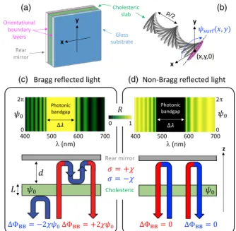
[20–22]. This is done by using a rear mirror [25], see Fig. 1(a), which displays a cholesteric slab sandwiched between a glass substrate (at z ¼ 0) and a standard mirror (at z ¼ L) that are associated with boundary layers provid-ing identical in-plane liquid crystal orientation patterns given by the spatially varying angle ψsurfðx; yÞ. The
demonstration is made in the context of spin-to-orbital angular momentum mapping, which covers various aspects of classical and quantum optics [26], and for which the polychromatic option is not available to date.
Cholesterics are characterized by a helical structure with pitch p that is the distance over which the local liquid crystal optical axis rotates by 2π around the z axis and by handedness χ ¼ $1; see Fig. 1(b). From the optics of uniform cholesterics [i.e., ψsurfðx; yÞ ¼ ψ0 with ψ0
con-stant], light propagating along the helix axis experiences helicity-preserved Bragg reflection for the incident helicity σ ¼ −χ. This is associated with a photonic band gap defined by pn⊥ < λ < pnk, nk;⊥being the refractive index along and perpendicular to the liquid crystal director
[29,30]. On the other hand, light with σ ¼ þχ is
trans-mitted through the cholesteric. In our case, such light is reflected by the rear mirror, which flips the helicity. Backward light is thus Bragg reflected without helicity change by the back side of the cholesteric. Ensuing helicity-flipped reflection from the rear mirror is eventually transmitted through the cholesteric at fixed helicity. The
process is sketched in Fig.1(c)and discussed in Ref.[31]. Arbitrarily polarized light is thus fully Bragg reflected for optical frequencies inside the band gap; see Fig. 1(c). Outside the band gap, only a fraction of the incident light is Bragg reflected, see Fig.1(c), while the rest is reflected by the structure with flipped helicity, as depicted in Fig.1(d). The geometric Berry phase of Bragg reflected light,ΦBB,
strongly depends on the incident helicity, wavelength, and cholesteric orientational boundary conditions, see Fig. 2. However, the differential geometric phase ΔΦBB¼
ΦBBðψ0Þ − ΦBBð0Þ does not depend on the wavelength.
Namely, ΔΦBB¼ 2σψ0, and the generalization to
space-variant boundary conditions gives ΔΦBB¼ 2σψsurfðx; yÞ,
which is the main result of this work.
Experimentally, this is investigated by preparing a 10 μm-thick Bragg-Berry optical element made of the chiral liquid crystal material SLC79 (BEAM Co). The chiral film is sandwiched between two glass substrates coated by an azobenzene-based surface-alignment layer providing a q-plate design for the orientational boundary conditions [32]. Namely, ψsurf ¼ qφ, with q ¼ 1 and
φ ¼ arctanðy=xÞ. The cholesteric pitch is adjusted to provide a Bragg reflection spectrum centered around λ≳ 530 nm and the photonic band gap width is measured to be≃75 nm. Without the back mirror add-on, this optical element behaves as a polychromatic Bragg-Berry vortex generator (BBVG) for σ ¼ −χ only, hence loosing all the
assets of a q plate[26,32], as shown in the left part of Fig.3. In this figure, the direct observation of the reflected intensity profile under incident helicity σ ¼ $χ and vari-ous spectral cases are reported. In contrast, the latter issue is solved in the presence of the back mirror, as shown in the right part of Fig.3. This supports the creation of a Bragg-Berry q plate (BBQP) allowing broadband spin-to-orbital angular momentum mapping.
First, we recall the useful formalism of high-order Poincar´e spheres of integer order l [33], Pl; see Fig. 4.
Each point on the sphere corresponds to a unique optical stateΨl having two degrees of freedom,
Ψlða; bÞ ¼ ae−ilφcþþ beþilφc−; ð1Þ
(a)
(b)
FIG. 2. Bragg reflected geometric phase spectra for the same parameters as in Fig.1 for incident helicity σ ¼ ∓χ (a), (b).
(a)
(c) (d)
(b)
FIG. 1. (a) Generic mirror-backed Bragg-Berry optical element. (b) Helical cholesteric ordering for χ ¼ þ1. (c) Calculated helicity-independent reflectance spectra and principle of the helicity-controlled geometric phase for a uniform surface align-ment ψsurf ¼ ψ0, for Bragg reflected light. (d) Same as in panel
(c) for non-Bragg reflected light. Simulations are made using 4 × 4 Berreman formalism [27,28] at normal incidence, with
nglass¼ 1.52, nk¼ 1.72, n⊥¼ 1.42, p ¼ 340 nm, χ ¼ −1, L ¼ 10p,
d ¼ 0 and assuming a perfect mirror.
FIG. 3. Experimental comparison of the helicity-dependent vortex beam generation between BBVG and BBQP ( χ ¼ −1, q ¼ 1). Images refer to the reflected beam intensity at near-normal incidence (1° incidence angle) collected at∼1 m from the element illuminated by a circularly polarized collimated super-continuum laser beam with helicity σ, diameter ∼1 mm, with interference filters centered on λ1¼ 500 and λ2¼ 550 nm with
10 nm full width at half maximum transmission spectrum, or not (fλg). For each pair of panels, the images are recorded at fixed acquisition time for the camera. Insets refer to enhanced-signal images to stress the absence of geometric phase shaping of the residual Fresnel reflection from the BBVG glass substrate.
where (a, b) are complex numbers, jaj2þ jbj2¼ 1, and
c$ ¼ ðx $ iyÞ=pffiffiffi2 refers to the circular polarization unit vectors in the Cartesian unit basis (x, y, z). The mapping of the Poincar´e sphere of polarization to high-order Poincar´e sphere, namely, P0→ Pl, is actually achieved inside the
photonic band gap of a BBQP with handedness χ of order q according to the unitary transformation
Ψ0ða; bÞ ⟶ BBQP
χ;q Ψ2qðbe
iΦ1; aeiΦ2Þ; ð2Þ
where constantsΦ1;2 depend on λ, material properties and
considered geometry. Isomorphisms between ϕ and Φ1;2
ensure the full mapping between P0 and P2q.
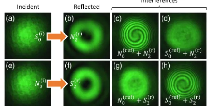
Without lack of generality, experiments are made using a collimated Gaussian laser beam with λ ¼ 532 nm and diameter ∼1 mm following the setup of Fig. 5. The reflected beam is analyzed by direct polarimetry (i.e., without reference beam) and by interferential measure-ments (i.e., with coaxial reference beam). The predicted mapping given by Eq. (2) is illustrated by analyzing the reflected far field for a representative set of incident states, namely,ΨðiÞ
0 ¼ ðS0; N0; H0; D0; V0; A0Þ. The case of
inci-dent circularly polarized light is summarized in Fig. 6
where the top or bottom rows refer toΨðiÞ
0 ¼ ðS0; N0Þ. The
observed doughnut intensity profile is the result of on-axis optical phase singularity. Maximum [Figs.6(c) and 6(h)] and minimum [Figs. 6(d) and 6(g)] visibility of the interference pattern, respectively, implies parallel and orthogonal circularly polarized reflected and reference fields. On the other hand, double-arm spirals reveal phase singularities with topological charge $2, whose sign is inferred from the spiral handedness. This demonstrates the transformations SðiÞ
0 → NðrÞ2 and NðiÞ0 → SðrÞ2 . Similar
analy-sis is performed for an incident linear polarization,
ΨðiÞ
0 ¼ H0, which is reported in the top row of Fig.7. In
that case, the reflected field is a superposition of contra-circularly polarized optical vortex beams with opposite topological charges two and equal weights; see Figs.7(c)
and 7(d). This agrees with the expected transformation HðiÞ
0 →ΨðrÞ0 ðeiΦ1=
ffiffiffi 2 p
; eiΦ2=pffiffiffi2Þ. More details are obtained
from spatially resolved polarimetric analysis of the reflected field (see Supplemental Material[25]) that unveils an inhomogeneous linearly polarized beam carrying polari-zation singularity with topological charge 2, see Fig.7(e), and average degree of linear polarization equals to 0.87. More generally, the transformations XðiÞ0 → XðrÞ2 with X ¼
ðH; D; V; AÞ are thus validated. Note that this implies a tuning of the gap (see Fig. 5) to ensure Φ1− Φ2¼ 0.
The preceding remark suggests that the isotropic phase delayΞiso¼ 8πd=λ associated with the optical path 4d of
the reflected field component with helicity σ ¼ χ, see Fig. 1(c), enables control of the BBQP at fixed incident polarization. Indeed, a dephasing Ξiso between the two
contracircularly polarized components corresponds to an angular displacement by an angleΔϕ ¼ Ξisoalong a line of
latitude on P2q. This is implemented by placing the rear
(a) (b)
FIG. 4. (a) High-order Poincar´e sphere Pl where any state
Ψlða; bÞ given by Eq.(1)corresponds to a point parametrized by
the angles (ξ, ϕ) with tanðξ=2Þ ¼ jb=aj and ϕ ¼ argða=bÞ. Six particular states are indicated and depicted in panel (b), where far-field intensity and polarization patterns are shown assuming an incident Gaussian beam. Nl and Sl, respectively, refer to
circularly polarized vortex fields associated with sz¼ $1 and
lz¼∓ 1; Hl, Dl, Vland Al, respectively, refer to space-variant
linearly polarized beams having azimuth angle of the form lφ, lφ þ π=4, lφ þ π=2 and lφ þ 3π=4.
FIG. 5. Sketch of the experimental setup. Here the gap between rear mirror (RM) and BBVG corresponds to an actual experimental situation. mirror (M); beam splitters (BS1;2;3); lens
with focal length f ¼ 0.5 m in f − f configuration with respect to the BBQP and the camera (L); polarizer (P); polarization controllers (PC1;2;3).
(a) (b) (c) (d)
(e) (f) (g) (h)
FIG. 6. Analysis of the reflected far field for ΨðiÞ
0 ¼ S0
(top row) and ΨðiÞ
0 ¼ N0 (bottom row). Interference intensity
patterns are obtained by coaxial coherent superposition with circularly polarized reference beam with helicity $1, namely ΨðrefÞ
0 ¼ ðN0; S0Þ. Superscripts (i), (r), and (ref) refer to incident,
mirror on a piezoelectric stage. The experiment is carried out by using a linearly polarized incident beam, which corresponds to a revolving exploration of the equator of P2q, see Fig.8. The rotating four-lobe intensity pattern with
a period that corresponds to ΔΞiso¼ 8π agrees with the
expected 2π rotation of a 4jqj-lobe intensity pattern for ΔΞiso¼ 8jqjπ in the general case.
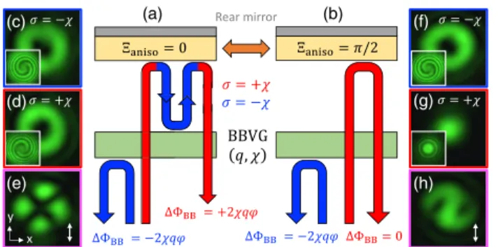
Reconfiguration of the BBQP at fixed incident polari-zation is also possible by imparting a birefringent phase retardationΞanisoto the back-reflected light. This allows us
to turn on and off the geometric phase shaping of the incident light with σ ¼ χ by switching Ξanisofrom 0 to π=2.
Indeed, Ξaniso¼ π=2 acts as a quarter-wave plate and its
combination with the rear mirror behaves as an effective helicity-preserving reflector, as sketched in Figs.9(a)and
9(b). Consequently, one can switch from high-order Poincar´e sphere Pl to hybrid-order Poincar´e sphere [34]
Pl;0 with Pl;l0 defining the optical states
Ψl;l0ða; bÞ ¼ ae−ilφcþþ beþil0φc−; ð3Þ
and noting that Pl;l≡ Pl. When l≠ l0 one obtains
so-called full Poincar´e beams [35] that refers to inhomoge-neously polarized beam whose local polarization states fully cover P0. Remarkably, our approach does not require
either to prepare an incident field with non-zero orbital state or detuning the geometric phase optical element, in contrast to the case of usual q plates. In our case, one can switch
between vectorial vortex beams (Ψl) and full Poincar´e beams of various kinds (Ψl;0 or Ψ0;l depending on χ).
This is illustrated in Figs. 9(c)–9(e) (Ξaniso¼ 0) and
Figs.9(f)–9(h)(Ξaniso¼ π=2).
As emphasized by Eq. (2), the dispersion on the high-order Poincar´e sphere prevents to have spatially super-imposed space-variant polarization patterns (except for q ¼ 1=2) although axisymmetric intensity distribution and topological phase shaping is properly achieved for each wavelength. Indeed, except for the north and south pole, any initial polychromatic state is mapped to a line of latitude on the output high-order Poincare sphere, each point corresponding to one wavelength. This could never-theless be corrected in a satisfying manner by adding a dispersion compensation scheme, for instance, by inserting a slab with negative refractive index ¯n ¼ −½ðn2
⊥þ n2kÞ=2'1=2
and thickness ¯L ¼ L=2 placed in between the back-mirror
(a)
(e)
(b) (c) (d)
FIG. 7. Top row: Analysis of the reflected far field forΨðiÞ
0 ¼
H0 with a presentation similar to that of Fig. 6. Bottom row:
Reconstruction of the polarization azimuth angle (Φ) of the reflected far field from spatially resolved Stokes polarimetry for the four distinct cases leading to HðrÞ
2 , DðrÞ2 , VðrÞ2 , and AðrÞ2 .
(a) (b)
FIG. 8. Revolving exploration of the equator of P2q by
isotropic phase control for q ¼ 1. Right part: Volumetric repre-sentation of the intensity patterns (without reference beam) obtained by setting PC1;3 as a linear polarizer, as Ξiso varies
over≃22π. Left part: transverse intensity profile snapshot.
(a) (c) (f) (g) (h) (d) (e) (b)
FIG. 9. (a), (b) On-demand activation of the geometric phase beam shaping of the incident light with σ ¼ χ by tuning the birefringent phase delayΞaniso. Far field intensity profiles of the
reflected light for incident helicity σ ¼ $χ are shown in panels (c),(d) and (f),(g). Insets: interference patterns. The case of incident linear polarization is shown in panels (e) and (h), when PC3 is set as a linear polarizer (↕). Left or right panels refer to
Ξaniso¼ ð0; π=2Þ, for q ¼ 1 and χ ¼ −1.
(a) (b)
(c)
FIG. 10. (a) Dispersion of the reduced latitude angle, ðϕ − hϕiλÞ=π on the high-order Poincar´e sphere for any incident
polarization state for ¯L ¼ L=2 with L ¼ 5p, 10p and 20p; λ0¼ pðnkþn⊥Þ=2 refers to the central wavelength of the
pho-tonic band gap and Δλ ¼ pðnk− n⊥Þ refers to the band gap width. Inset: standard deviation of ϕðλÞ in the photonic band gap versus the thickness ¯L of the compensating layer. (b), (c) Bragg reflected geometric phase spectra for L ¼ 10p and incident helicities σ ¼ $χ. Material parameters are those of Fig.1.
and the Bragg-Berry slab of thickness L. The quality of such a dispersion management is quantitatively addressed in Fig. 10(a) for three different values of L. The corre-sponding spectral dependence of the helicity-dependent reflected phase for the Bragg-reflected light is shown in Figs. 10(b) and 10(c), whose comparison with Fig. 2
illustrates well the sought-after dispersion compensation inside the photonic band gap. Another option—bulkier but easier to implement and that provides perfect compensation—consists of process incident photons with opposite helicity by two independent Bragg-Berry vortex generators with identical q and opposite χ using a two-arm configuration with equal optical path, as sketched in the Supplemental Material, Fig. S4[25].
In conclusion, we note that although the present work is carried out in the specific framework of spin to orbital angular momentum mapping using q-plate design, it applies to all possible kinds of wave fronts that are shaped by the geometric phase. These results should therefore be useful for the optics and photonics community at large, even when dealing at the single photon level.
This study has been carried out with financial support from the French National Research Agency (Project No. ANR-15-CE30-0018).
[1] J. Elton,Int. J. Hist. Eng. Tech. 79, 183 (2013).
[2] Y. Zhao, X.-X. Liu, and A. Alu,J. Opt. 16, 123001 (2014). [3] N. Yu and F. Capasso,Nat. Mater. 13, 139 (2014). [4] P. Genevet and F. Capasso, Rep. Prog. Phys. 78, 024401
(2015).
[5] R. Bhandari,Phys. Rep. 281, 1 (1997).
[6] Z. Bomzon, G. Biener, V. Kleiner, and E. Hasman, Opt. Lett. 27, 1141 (2002).
[7] G. Biener, A. Niv, V. Kleiner, and E. Hasman,Opt. Lett. 27, 1875 (2002).
[8] K. Y. Bliokh, F. J. Rodriguez-Fortuno, F. Nori, and A. V. Zayats,Nat. Photonics 9, 796 (2015).
[9] T. Wakayama, K. Komaki, Y. Otani, and T. Yoshizawa,Opt. Express 20, 29260 (2012).
[10] T. Wakayama, O. G. Rodríguez-Herrera, J. S. Tyo, Y. Otani, M. Yonemura, and T. Yoshizawa, Opt. Express 22, 3306 (2014).
[11] F. Bouchard, H. Mand, M. Mirhosseini, E. Karimi, and R. W. Boyd,New J. Phys. 16, 123006 (2014).
[12] N. Radwell, R. D. Hawley, J. B. Götte, and S. Franke-Arnold,Nat. Commun. 7, 10564 (2016).
[13] Y. Li, J. Kim, and M. J. Escuti,Proc. SPIE Int. Soc. Opt. Eng. 8274, 827415 (2012).
[14] J. Kobashi, H. Yoshida, and M. Ozaki,Nat. Photonics 10, 389 (2016).
[15] M. Faryad and A. Lakhtakia,Adv. Opt. Photonics 6, 225 (2014).
[16] J. Kim, Y. Li, M. N. Miskiewicz, C. Oh, M. W. Kudenov, and M. J. Escuti,Optica 2, 958 (2015).
[17] P. Chen, B.-Y. Wei, W. Ji, S.-J. Ge, W. Hu, F. Xu, V. Chigrinov, and Y.-Q. Lu,Photon. Res. 3, 133 (2015). [18] M. Rafayelyan, G. Tkachenko, and E. Brasselet,Phys. Rev.
Lett. 116, 253902 (2016).
[19] R. Barboza, U. Bortolozzo, M. G. Clerc, and S. Residori, Phys. Rev. Lett. 117, 053903 (2016).
[20] M. Rafayelyan and E. Brasselet, Opt. Lett. 41, 3972 (2016).
[21] J. Kobashi, H. Yoshida, and M. Ozaki,Phys. Rev. Lett. 116, 253903 (2016).
[22] M. Rafayelyan, G. Agez, and E. Brasselet,Phys. Rev. A 96, 043862 (2017).
[23] J. Kobashi, H. Yoshida, and M. Ozaki, Mol. Cryst. Liq. Cryst. 646, 116 (2017).
[24] P. Chen, L.-L. Ma, W. Duan, J. Chen, S.-J. Ge, Z.-H. Zhu, M.-J. Tang, R. Xu, W. Gao, T. Li, W. Hu, and Y.-Q. Lu,Adv. Mater. 30, 1705865 (2018).
[25] See Supplemental Material at http://link.aps.org/ supplemental/10.1103/PhysRevLett.120.213903 for an-other option to add a second space-variant cholesteric slab with opposite chirality and identical surface patterning, which is, however, more difficult to realize experimentally than a simple reflective coating at the back of the optical element. The working principle of such bilayered Bragg-Berry option is illustrated.
[26] L. Marrucci, E. Karimi, S. Slussarenko, B. Piccirillo, E. Santamato, E. Nagali, and F. Sciarrino,J. Opt. 13, 064001 (2011).
[27] D. W. Berreman,J. Opt. Soc. Am. 62, 502 (1972). [28] We adopt the following convention for the complex
repre-sentation of a paraxial beam propagating along the $z axis. Namely, its complex amplitude is taken proportional to the propagation factor expð−iωt $ ik0zÞ with ω the angular
frequency, t the time, and k0 the free-space wave vector.
[29] V. A. Belyakov, Diffraction Optics of Complex-Structured Periodic Media (Springer, New York, 1992).
[30] P. Oswald and P. Pieransky, Nematic and Cholesteric Liquid Crystals: Concepts and Physical Properties Illustrated by Experiments (Taylor & Francis, CRC, Boca Raton, FL, 2005).
[31] S. Erten, S. E. Swiontek, C. M. Graham, and A. Lakhtakia, J. Nanophoton. 9, 090599 (2015).
[32] L. Marrucci, C. Manzo, and D. Paparo,Phys. Rev. Lett. 96, 163905 (2006).
[33] G. Milione, H. I. Sztul, D. A. Nolan, and R. R. Alfano,Phys. Rev. Lett. 107, 053601 (2011).
[34] X. Yi, Y. Liu, X. Ling, X. Zhou, Y. Ke, H. Luo, S. Wen, and D. Fan,Phys. Rev. A 91, 023801 (2015).
[35] A. M. Beckley, T. G. Brown, and M. A. Alonso, Opt. Express 18, 10777 (2010).