Publisher’s version / Version de l'éditeur:
Vous avez des questions? Nous pouvons vous aider. Pour communiquer directement avec un auteur, consultez la première page de la revue dans laquelle son article a été publié afin de trouver ses coordonnées. Si vous n’arrivez pas à les repérer, communiquez avec nous à [email protected].
Questions? Contact the NRC Publications Archive team at
[email protected]. If you wish to email the authors directly, please see the first page of the publication for their contact information.
https://publications-cnrc.canada.ca/fra/droits
L’accès à ce site Web et l’utilisation de son contenu sont assujettis aux conditions présentées dans le site
LISEZ CES CONDITIONS ATTENTIVEMENT AVANT D’UTILISER CE SITE WEB.
Canadian Building Digest; no. CBD-127, 1970-07
READ THESE TERMS AND CONDITIONS CAREFULLY BEFORE USING THIS WEBSITE. https://nrc-publications.canada.ca/eng/copyright
NRC Publications Archive Record / Notice des Archives des publications du CNRC :
https://nrc-publications.canada.ca/eng/view/object/?id=66ac1431-227d-4f57-ae49-3ca04920f16a
https://publications-cnrc.canada.ca/fra/voir/objet/?id=66ac1431-227d-4f57-ae49-3ca04920f16a
NRC Publications Archive
Archives des publications du CNRC
For the publisher’s version, please access the DOI link below./ Pour consulter la version de l’éditeur, utilisez le lien DOI ci-dessous.
https://doi.org/10.4224/40000790
Access and use of this website and the material on it are subject to the Terms and Conditions set forth at
The structure of porous building materials
Canadian Building Digest
Division of Building Research, National Research Council Canada
CBD 127
The Structure of Porous Building
Materials
Originally published July 1970 P.J. Sereda
Please note
This publication is a part of a discontinued series and is archived here as an historical reference. Readers should consult design and regulatory experts for guidance on the applicability of the information to current construction practice.
Porous materials such as stone, brick, concrete and wood are far from being the simple materials their extensive use suggests. They are much more complex, for example, than sophisticated materials like the silicon wafers used in transistors. Understanding of their structure is essential, therefore, if reliable prediction is to be made of their response to various conditions of exposure.
The constitution of all solid materials is ultimately resolved as an assemblage of atoms of one or more elements. These are organized in particular groupings to form molecules, crystals or particles acting as micro-units from which the physical structure of any solid material is constructed.
All physical and chemical changes in a material originate on the scale of the atom or micro-unit, whereas they are normally observed on the scale of man's visual perception. When any event in a material is observable, it has progressed to a stage where millions of atoms are involved. For this reason it is useful to establish a relative scale for comparison. If a grain of fine sand represents the limit of visual perception (about 100 microns; 1 micron = 1 millionth of a meter), then an atom is so small that about 1 million must be put side by side to make up the grain of sand. The Ångström unit, Å, is used for the atomic scale (1 micron = 10,000 Å). Various assemblages of atoms that form the structural micro-units of materials are usually less than a micron in size and thus must be magnified more than 100 times to be seen.
Atoms are the basic chemical building units. Reactions take place between atoms (as ions) to form molecules, which in turn assemble into crystals or amorphous particles and, finally, into the familiar common materials. For the purpose of this Digest it is sufficient to note that the chemical nature of a material is determined by the basic chemical unit, the molecule. In organic materials the "backbone" of the molecules is a carbon-to-carbon linkage, with side connections of hydrogen as well as carbon, oxygen, and other elements. The particular elements and their arrangement as well as the number of atoms determine the chemical nature of the molecule. For example, a chain of six carbon atoms and a complement of 14 hydrogen atoms form the solvent hexane; a carbon chain of up to 1/4 million carbon atoms forms the plastic, polyethylene. Some general aspects of organic materials are discussed in CBD 117.
In the major inorganic class of materials such as clays and cement the common backbone of the silicates is the silica tetrahedron. This unit forms a tetrahedron shape and permits a great variety of structural configurations by joining at the apex of adjacent units. The chemical nature of the material is the final result of the chemically bonded atoms of the different elements forming the compound.
In some materials such as metals the bulk is comprised of a single element, with only trace amounts of other elements as impurities or intentionally added alloying constituents. Most of the metals used in construction are produced from the molten state by solidifying them into micro-crystals whose growth terminates at boundaries of neighbouring crystals. These solids are usually non-porous in the sense that the boundaries are close enough to exclude the possibility that foreign atoms can penetrate the interior.
This Digest is concerned mainly with the class of materials designated as porous. This includes ceramics, concrete, stone, and brick, as well as organic coatings, wood (wood products) and cellulose products.
Micro-Units
All building materials are mixtures of a number of chemical compounds identified as molecules. The compounds either crystallize into various definite shapes or solidify from the molten state as formless particles to make up the micro-units. These are the physical building blocks from which all building materials are constituted.
Having recognized that micro-units are the physical building blocks, it follows that physical and mechanical properties must be determined by these units, their arrangement, and connections. Viewed on this scale (magnified 10,000x) where detail of the microstructure can be clearly seen, there is order, complexity and great variety. As building materials include a large number of compounds, they contain a range of crystalline systems composed of various shapes of units, including cubes, plates, needles, and tubes, as well as amorphous (shapeless) particles. Usually a specific material will be a mixture of several compounds and consequently a mixture of differently shaped particles, with a wide range of sizes.
Porosity
Porosity can be defined as any space between micro-units that is greater than normal atomic dimensions so that foreign molecules such as water can penetrate it. The water molecule is only 3.5 Å units in diameter and water can therefore enter the pores whenever the boundary between micro-units is greater than this size. Usually the pores are considerably larger than molecular dimensions and are of different sizes often ranging from very large to micro-size, and are generally interconnected, providing continuous channels to the outside boundary of the material.
In some special cases where a material has a layered structure, as in clay or hydrated cement, water molecules by virtue of chemical affinity can separate the layers even when they are very closely spaced. The special micro-pores thus created are referred to as inter-layer spaces and are not included as porosity. Water molecules as well as other gas molecules may be diffused through material classed as non-porous (i.e. plastics), but the rate is insignificant compared with that through porous materials.
When solids are formed by reactions such as hydration of plaster of paris or cement, with consequent growth of numerous crystals of various size and shape, the result is a structure of microunits making direct contact with each other only at some points on the growing faces of the crystals. The remainder of the surfaces do not come together but leave spaces of varying size and shape. These represent pores, which can be micro-size, as well as larger capillaries and channels.
It will be appreciated that such a system of pores is interconnected and communicates with the outside of the body of the material. The total volume of such space, as a percentage of the total volume of the solid and pores, is defined as the porosity of the material. The porosity of
common materials such as plaster is in the range of 50 to 65 per cent, of concrete, 40 to 60 per cent, and of brick, 5 to 50 per cent. Materials that are fused or sintered from an aggregation of particles begin as a highly porous system, but if fusion takes place at high temperature and is accompanied by pressure, as in hot-pressing of ceramics, the resulting porosity can be relatively low.
Bond
The microstructure of a material results from the assembly of the micro-units forming the structure. If the assembly of micro-units is to result in a strong body there must be a strong connection or bond between units. In some instances connections are made by virtue of chemical linkage, as occurs in cross-linking of polymer molecules, to make them much stronger. In other cases crystal boundaries merge during their growth to provide an efficient connection, as for metals and, to some degree, plasters. Most often (in the common cementing systems) the bond is simply the physical attraction of one solid for another, the van der Waals' force, which relies on the close proximity of the atoms in the adjacent surfaces to keep them together.
As the size of micro-units decreases and total surface area increases the area in close contact will increase. A strong cementing action results when portland cement hydrates because of the very small size of the particles created by the hydration process. The great increase in total surface area in a confined space brings adjacent surfaces so close that strong bonds are established. Very fine particles in a dry state can be formed into a strong, rigid body if sufficient pressure is applied to bring the particles into close proximity.
Microstructure
When a material is formed, its physical and mechanical properties will be influenced by the nature of the micro-units, their size and shape, the manner of their nucleation and growth, the nature of the boundary formed by the interference of growing surfaces, the area of this boundary, and the extent of surfaces that do not come together but leave spaces represented by porosity.
In metals, special ceramics, and certain rocks the boundary between grains is continuous and the stress on the material is shared proportionately and uniformly by the individual micro-units (Figure 1a). In a similar manner, a microstructure formed from individual crystals or particles that intergrow at points of contact or are joined by fusion represents a potentially strong material if the area of the interface boundary is large (Figure 1b and Figure 1c). Of the many factors that should influence the formation of a microstructure it has not been possible to identify and relate the effect of each on the final properties of the material.
Figure 1a. Quartz crystals, non-porous system (Courtesy Sperry Rand Research Center).
Figure 1c. Gypsum, hydrated from plaster of paris and water, porosity 30 per cent.
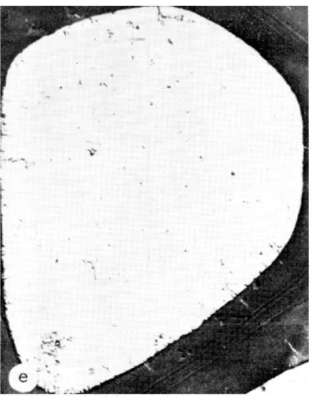
Figure 1e. Wood cell (Micrograph courtesy State University College of Forestry at Syracuse University).
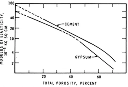
Only total porosity has so far shown a relation with strength and modulus of elasticity. Figure 2 shows this relation for plaster and cement, but similar semi-logarithmic relations have been found for many materials. Because of this, small changes in porosity can cause large changes in modulus and strength. Concrete can be brought to a strength of over 20,000 psi and cement paste to over 30,000 psi by special techniques of compaction that provide the lowest possible porosity. No particular formulation of the cement is involved. Even for special compaction of clays, similar strengths can be achieved. Hydrated plaster can be as strong as cement if the porosity is decreased below that normal for the material. Figure 1c shows the needle-like crystals intergrowing and forming a network of braces in three directions not unlike a three-dimensional truss.
Figure 2. Porosity to modulus relation.
The microstructure of cement at early stages of hydration resembles a clay system of plates and rods, except that there is evidence of more positive connections and a three-dimensional network almost like a geodesic structure. When cement has completely hydrated, however, the structure (Figure 1d) has very few of the large pores evident earlier, although the micro-porosity of what appears to be a solid structure is still about 30 per cent. Micropores in this structure are of the order of 10 to 100 Å in size and would require a magnification of at least 30,000 to be visible. Figure 1d shows the typical structure; it has micro-porosity, but at this magnification it cannot be seen.
Nature produces porous organic materials such as wood in which the geometry is quite regular and the micro-units are of a regular shape and uniform arrangement. Wood as a structural material has been discussed in CBD 85, CBD 86 and CBD 88. Figure 1e is a micrograph of a section of wood cell at a right angle to the grain. Total porosity is greater than in any of the previous examples, but the mechanical properties of strength and modulus are higher than would be expected for such a porous system. This is because the micro-units are assembled in the manner of a composite, where the wood cells in the shape of tubes are bonded along their length with other wood cells by the cementing action of the lignin. Wood is perhaps the best example of a natural composite. It also demonstrates the great potential of synthetic composite materials: the fibreglass fishing rod is man's copy of a wood composite.
An inevitable consequence of micro-structure where porosity exists is the fact that the total internal surface of a material (represented by the boundaries of the internal space) will be exposed to the aggressive action of the environment if the space communicates with the outside. It allows foreign agents to penetrate the "heart" of the material. Because the micro-units are usually very small, this internal surface can be very large. A pound of hydrated cement in concrete, which has a layered or folded sheet structure and interconnected space, will have a total surface area of about 5.5 acres. The significance of this will be discussed in a future Digest.
Originally published June 1970. C.R. Crocker
The service life of materials is greatly influenced by the environment in which they are required to serve. In most cases the limits of the environmental conditions are known, but the variations that exist because of orientation often have a profound effect on the durability of sealants, mortar, masonry and other wall components. It is the purpose of this Digest to indicate the effects of orientation, particularly as it relates to temperature and moisture.
Under ideal conditions absorption of solar radiation can increase the exterior wall surface temperature above the ambient air temperature by almost 90 fahrenheit degrees. This creates large variations in the conditions of exposure of exterior wall materials because solar radiation is not received uniformly on all elevations of a building.
Vertical walls receive their maximum irradiation on a clear day with the sun at an altitude of 25 or 30 degrees and directly in front of the wall. At lower sun angles irradiation is reduced by atmospheric absorption. The time of day and day of the year when a wall receives its maximum irradiation depend on both latitude and orientation.
In southern Canada north-facing walls receive solar radiation from sunrise until about 8 a.m. and again from about 4 p.m. until sunset during most of the spring and summer. At Ottawa the maximum irradiation on a north wall, sufficient under ideal conditions to raise the surface temperature by 16 degrees, is received at about 6 a.m. and again at 6 p.m., standard time, on 21 June.
East and west elevations receive large amounts of irradiation during the summer because they face directly into the sun when its altitude is around 30 degrees. Both elevations receive their maximum irradiation, regardless of latitude, around 21 April, the east wall about 8 a.m. and the west wall about 4 p.m. Irradiation remains at a high level throughout the summer months, but starts to fall off in September.
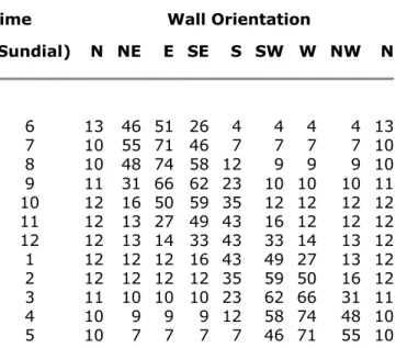
Although south walls receive the greatest total annual irradiation, they do not receive the maximum in summer, because the sun is too high in the sky. During the winter the sun is at a much lower altitude and it is then they receive the maximum. At Ottawa, this is recorded at noon near the end of January; at Edmonton, at a higher latitude, it is received at the end of February. Prior to these dates, the sun is below the optimum altitude for maximum irradiation. The figures in Table I give the maximum rise above ambient air temperature that a vertical surface attains as a result of absorption of solar radiation. The given values are for 21 July. It has been assumed that the day is cloudless with no wind, that the atmosphere is clear, the surface of the wall black, and the wall lightweight and well insulated. (Light coloured walls could reduce the temperature rise by half.) For massive concrete or masonry walls the values would be lower due to the conduction of heat into the walls and the high heat storage capacity of such constructions.
Table I. Maximum Temperature Rise of Vertical Wall Surface due to solar Radiation. Ottawa, 21 July
Time Wall Orientation
(Sundial) N NE E SE S SW W NW N 6 7 8 9 10 11 12 1 2 3 4 5 13 10 10 11 12 12 12 12 12 11 10 10 46 55 48 31 16 13 13 12 12 10 9 7 51 71 74 66 50 27 14 12 12 10 9 7 26 46 58 62 59 49 33 16 12 10 9 7 4 7 12 23 35 43 43 43 35 23 12 7 4 7 9 10 12 16 33 49 59 62 58 46 4 7 9 10 12 12 14 27 50 66 74 71 4 7 9 10 12 12 13 13 16 31 48 55 13 10 10 11 12 12 12 12 12 11 10 10
6 13 4 4 4 4 26 51 46 13
Temperature Variations
Variation in temperature at any given time of surfaces with different orientations can be quite large. For example, in summer at 8 a.m. there can be a 65 degree temperature difference between the surface of an east wall and that of a west wall. The same variation can occur, in reverse, at 4 p.m. In the afternoon the actual surface temperatures will be higher because the ambient air temperatures are invariably higher.
Variation of temperatures in winter is even more striking. At noon, for example, an 81 degree temperature difference can occur between the surface of a south wall and all others oriented 90 degrees or more from the south. Even with an ambient temperature of -20°F, the surface of a wall oriented south-east, south or south-west can attain temperatures well above the freezing point.
Freeze-Thaw Action
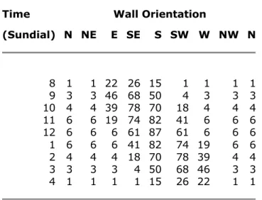
The exterior surface temperature of materials on walls with a northern orientation is close to ambient air temperature during the winter months (see Table II). Materials with a southern exposure, on the other hand, are subjected to wide variations in temperature. Not only does this place greater stress on sealants and mortars but also increases the number of freeze-thaw cycles.
Table II. Maximum Temperature Rise of Vertical Wall Surface due to solar Radiation. Ottawa, 21 January
Time Wall Orientation
(Sundial) N NE E SE S SW W NW N 8 9 10 11 12 1 2 3 4 1 3 4 6 6 6 4 3 1 1 3 4 6 6 6 4 3 1 22 46 39 19 6 6 4 3 1 26 68 78 74 61 41 18 4 1 15 50 70 82 87 82 70 50 15 1 4 18 41 61 74 78 68 26 1 3 4 6 6 19 39 46 22 1 3 4 6 6 6 4 3 1 1 3 4 6 6 6 4 3 1
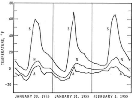
To illustrate the influence of orientation in freeze-thaw cycling, graphs in Figure 1 show the air temperature and corresponding surface temperatures of north- and south-facing walls of a DBR test building constructed of brick and located in Ottawa. The temperature of the bricks on the south wall rose above and fell below 32°F, causing a thawing and freezing cycle in the brickwork. The air temperature remained below 32°F, as did the temperature of the bricks on the north wall.
Figure 1. Air temperature and brick surface temperature of north- and south-facing walls. Legend: A air temperature; N north wall surface temperature; S south wall surface temperature.
During the three winter months bricks of the north wall of the test building were subjected to 27 freeze-thaw cycles, while those of the south wall experienced 67 cycles. The number of freeze-thaw cycles experienced by bricks exposed over one winter in Ottawa and Halifax is given in Table III. Winters with below-normal temperatures would show the greatest variation in freeze-thaw cycling for northern and southern exposures. In most areas of Canada such winters have above-normal sunshine, with corresponding increase in freeze-thaw cycles for walls with a southern exposure.
Table III. Geographical and Directional Effects On Freeze-Thaw Cycles of Bricks Brick Facing Number of Freeze-ThawCycles In One Winter
Ottawa Halifax North East South West 65 70 98 79 81 83 108 88 Wind
Wind affects the exterior surface temperature of all elevations of a building more or less equally. The more important aspects of wind in relation to the orientation of walls have to do with air leakage out of buildings and rain wetting of walls.
In the greater part of Canada prevailing winds blow from a north-westerly direction during the winter months. Thus buildings are frequently subjected to suction pressures on the southerly exposures. These negative pressures combine with those of stack effect to induce air leakage outward from the interior of the building (CBD 104). As has been discussed in another Digest (CBD 72), air leakage is the principal mechanism by which water vapour is transferred into the wall. Thus, in winter, conditions prevail that may lead to additional condensation in walls with southerly exposure. then sufficient moisture is available, porous materials can become saturated, with consequent damage when frozen. Observations confirm, however, that solar
radiation promotes drying of wall materials and on southerly exposures there is actually less damage than on easterly exposures where materials dry more slowly, although still subjected to increased freeze-thaw cycling. Here, moisture content may be a more critical factor than the number of freeze-thaw cycles.
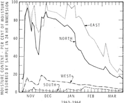
The wetting of walls by rain is the result of wind action. Studies carried out in Ottawa and Halifax show great variations in the moisture content of brick exposed to the cardinal points of the compass. The graphs in Figure 2 show the moisture content of bricks exposed at Ottawa during the winter 1963-64 in such a way that only the face could be wetted by rain. The bricks facing south and west received very little rain, but those facing north and east had a high moisture content from wind-driven rain.
Figure 2. Directional effect on the rain-wetting of bricks exposed at Ottawa.
Similar bricks exposed at Halifax during the same period received more moisture than those in Ottawa and the directional effect was different. Bricks facing north received the least rain; those facing east and south received the most and reached the highest moisture content.
The wetting of full-scale building walls exhibits a more complex pattern influenced by the aerodynamics of the particular situation and projections on the surface that deflect the flow of water. Again, materials on the southerly exposure, even if wetted by rain, may be able to dry more quickly and are less liable to damage from freeze-thaw cycling.
Summary
Orientation influences the severity of the exposure to which walls are subjected. Temperatures at any given time can vary as much as 90 degrees due to solar radiation; and the number of freeze-thaw cycles can subsequently be increased as the result of solar radiation. wetting of walls, as influenced by prevailing winds and air leakage patterns, is also of significance with respect to the environment in which materials must serve.