Computational Design of Foldable
Robots via Composition
by
Cynthia Rueyi Sung
B.S., Rice University (2011)
S.M., Massachusetts Institute of Technology (2013)
Submitted to the Department of
Electrical Engineering and Computer Science
in partial fulfillment of the requirements for the degree of
Doctor of Philosophy in Electrical Engineering and Computer Science
at the
MASSACHUSETTS INSTITUTE OF TECHNOLOGY
September 2016
© Massachusetts Institute of Technology 2016. All rights reserved.
Author . . . .
Department of
Electrical Engineering and Computer Science
August 31, 2016
Certified by. . . .
Daniela Rus
Andrew (1956) and Erna Viterbi Professor
Thesis Supervisor
Accepted by . . . .
Leslie A. Kolodziejski
Chair, Department Committee on Graduate Students
Computational Design of Foldable Robots via Composition
by
Cynthia Rueyi Sung
Submitted to the Department of Electrical Engineering and Computer Science on August 31, 2016, in partial fulfillment of the
requirements for the degree of
Doctor of Philosophy in Electrical Engineering and Computer Science
Abstract
Recent advances in rapid fabrication technologies have given designers the ability to manufacture increasingly complex geometries with little increase in cost, making it easier than ever to build a robot. However, the process of designing a functional robot remains challenging. Robots are complex systems that tightly integrate mechanical, electrical, and software subsystems. As a result, traditional robot development often requires iterations of design and testing to ensure that the result is both functional and manufacturable.
This thesis explores intuitive design tools for robot design and proposes composi-tion as a design approach. We leverage a print-and-fold paradigm of manufacturing, which has been shown to enable functional robots to be created within a day. The main challenge in using composition is that in general, even if two modules func-tion correctly individually, the combinafunc-tion of the two may not be a valid design. We therefore develop algorithms and systems for robot composition that guarantee validity of the design geometry and that check the resulting kinematics.
Our main contributions include a database containing parameterized designs for printable joints and mechanisms, algorithms for composition of fold patterns and motion sequences that guarantee no self-intersection, automated generation of fab-rication plans for multiple modes of print-and-fold fabfab-rication, an interactive user interface in which users can compose custom robots and receive real-time feedback about their designs, and experimental verification in the form of functional mecha-nisms and robots. The results provide designers with a framework for rapid design exploration and bring us closer to a future of easy robot design and customization. Thesis Supervisor: Daniela Rus
To my family, with love.
Acknowledgments
This thesis would never have been completed without the help and support of many people.
First and foremost, I would like to thank my research advisor, Daniela Rus, who has been an awesome mentor throughout the course of my Ph.D. Daniela has always been available to answer any of my many questions, and she has taken a genuine interest in not only my research progress but also my motivation and general happi-ness. Her enthusiasm for robotics and its potential to change the world is infectious, and her drive to always “Keep the gradient!” has made her one of my greatest role models. Daniela, thank you so much for your guidance and support!
I would also like to thank my thesis committee members: Erik Demaine, Wojciech Matusik, and Vijay Kumar. Even before joining this committee, all three of them have provided insightful comments and advice on the research. Erik is primarily responsible for bringing me into the world of folding theory, while Wojciech introduced me to data-driven techniques, and Vijay has kept me grounded in practical application considerations. Their feedback has raised the level of this research considerably.
To all the members of the Distributed Robotics Lab extended family, I would like to express the greatest appreciation. On the technical side, I would particularly like to recognize Cagdas Onal and Michael Tolley, who introduced me to the idea of printable robots; Joseph DelPreto, who has let me “borrow” his electronics parts countless times; Brian Julian and Mehmet Dogar, who helped me to take motion cap-ture measurements; and Ankur Mehta, Shuhei Miyashita, John Romanishin, Adriana Schulz, and Andrew Spielberg, who have all been valuable collaborators. I have been fortunate to have had the support of amazing technicians such as Ron Wiken, lab as-sistants Kathy Bates and Mieke Moran, and undergraduate researchers James Bern, Elizabeth Hadley, and Rhea Lin, whose high skills are only matched by their enthu-siasm. Personally, I would also like to thank Andrew Marchese, who was the first to welcome me to the lab and who was always willing to answer any questions I had
about the Ph.D., as well as Nora Ayanian and Ross Knepper for their continuous motivational support.
Last but not least, I would like to thank my family: my mother, Chin Fong Pau, who has been there for all my successes and failures and who probably knows as much about this thesis as I do; my father, Chung Shin Sung, who is always willing to speculate about its potential impact on the world; and my siblings, Angela and Eric, who are always interested in talking about the latest in science and engineering. I dedicate this thesis to you.
This work was done in the Distributed Robotics Laboratory at MIT with support from NSF Grant Numbers 1240383 and 1138967, and from the Department of De-fense (DoD) through the National DeDe-fense Science & Engineering Graduate (NDSEG) Fellowship Program. I am grateful for their support.
Contents
List of Figures 13 List of Tables 17 List of Algorithms 19 1 Introduction 21 1.1 New Capabilities . . . 22 1.2 Challenges . . . 23 1.3 Design by Composition . . . 251.3.1 Scope and Limitations . . . 25
1.4 Thesis Contributions . . . 26
1.5 Thesis Organization . . . 28
2 Related Work 29 2.1 Rapid Fabrication . . . 29
2.1.1 Origami-Inspired Fabrication . . . 30
2.2 Computational Design of Robots and Functional Mechanisms . . . 32
2.2.1 Fully Automated Design . . . 32
2.2.2 Interactive Design . . . 33
2.3 Design by Composition . . . 35
2.4 Origami-Inspired Engineering . . . 36
2.4.1 Static Structures . . . 36
3 Notation 39
4 Transformable Foldable Modules 43
4.1 Parametric Designs . . . 44
4.1.1 Definitions . . . 44
4.1.2 Hinge Joint . . . 45
4.1.3 Prismatic Joint . . . 46
4.1.4 Pivot Joint . . . 47
4.2 Pseudo-Rigid Body Analysis . . . 49
4.2.1 Hinge Joint . . . 50
4.2.2 Prismatic Joints . . . 51
4.2.3 Pivot Joint . . . 53
4.3 Experimental Comparisons . . . 55
4.3.1 Electronics Integration . . . 56
4.3.2 Force and Torque Measurements . . . 58
4.4 Summary . . . 64
5 Composition of Foldable Mechanisms 65 5.1 Problem Statement . . . 66
5.1.1 Representation . . . 68
5.2 Composition Algorithm . . . 68
5.2.1 Main Insight: Edges on the Convex Hull Boundary . . . 68
5.2.2 Constructing the Bridge . . . 70
5.2.3 Optimizations . . . 77
5.2.4 Face-Composition . . . 77
5.3 Correctness and Material Usage Guarantees . . . 77
5.3.1 Pleat Creation . . . 78
5.3.2 Bridging Exterior Edges . . . 81
5.3.3 Bridging Interior Edges . . . 83
5.3.4 Full Composition Algorithm . . . 84
5.4.1 Compositions of Rigid Bodies . . . 85
5.4.2 Joints with Multiple Degrees of Freedom . . . 88
5.4.3 Mechanisms . . . 89
5.4.4 Foldable Robots . . . 91
5.5 Summary . . . 93
6 Composition of Foldable Ground Robots 95 6.1 Gait and Trajectory Design . . . 96
6.1.1 Joint Controllers . . . 97 6.1.2 Gait Design . . . 98 6.1.3 Trajectory Design . . . 98 6.2 Performance Metrics . . . 99 6.2.1 Simulation . . . 99 6.2.2 Metrics . . . 101
6.3 Fabrication and Assembly . . . 103
6.3.1 Electronics . . . 103 6.3.2 Software . . . 104 6.3.3 Robot Body . . . 104 6.3.4 Assembly . . . 106 6.4 Experimental Results . . . 106 6.4.1 Fabricated Robots . . . 106
6.4.2 Extensions Beyond the Database . . . 109
6.4.3 Optimization . . . 109
6.4.4 Fabrication Comparison . . . 110
6.5 Summary . . . 111
7 Interactive Design 113 7.1 User Interface and Workflow Overview . . . 114
7.1.1 Geometry Composition . . . 116
7.1.2 Motion Composition . . . 120
7.2 User Study . . . 124
7.2.1 Geometry Design . . . 124
7.2.2 Combined Geometry and Gait Design . . . 125
7.2.3 Interactive Feedback and Optimization . . . 127
7.3 Summary . . . 128
8 Extensions to Other Fabrication Methods 131 8.1 Medium Scale Fabrication and Design . . . 131
8.1.1 Fabrication Process . . . 132
8.1.2 Pattern Generation . . . 133
8.1.3 Fabricated Results . . . 137
8.2 Large Scale Fabrication and Design . . . 141
8.2.1 Fabricated Results . . . 142 8.3 Summary . . . 144 9 Conclusion 145 9.1 Lessons Learned . . . 146 9.2 Limitations . . . 148 9.3 Future Work . . . 149
A Sample Output Fabrication Plan 151 A.1 Generated Print . . . 152
A.2 Electronics Plan . . . 152
A.3 Generated Code . . . 153
B User Study Questionnaire Responses 163 B.1 Pre-study Questionnaire . . . 163
B.2 Task 1 Questionnaire . . . 164
B.3 Task 2 Questionnaire . . . 167
B.4 Task 3 Questionnaire . . . 171
List of Figures
2-1 Previous foldable robots . . . 31
4-1 Folding definitions . . . 44
4-2 Summary of fold patterns and folded states for three basic joint types with input parameters indicated . . . 45
4-3 Prismatic joint construction . . . 47
4-4 Motion of 1 layer of a pivot joint with all black lines having unit length 48 4-5 Elongation of folds in a pivot joint over the course of rotation for num-ber of sides between 5 and 10 . . . 48
4-6 Pivot joint construction . . . 49
4-7 Cross-sectional view of hinge joint with active folds labeled . . . 50
4-8 Diagram of 2-layer prismatic joint . . . 52
4-9 Diagram of a single square linkage on a pivot joint . . . 54
4-10 Joints folded from polyester film in two different positions . . . 56
4-11 Hinge joint with integrated electronics . . . 57
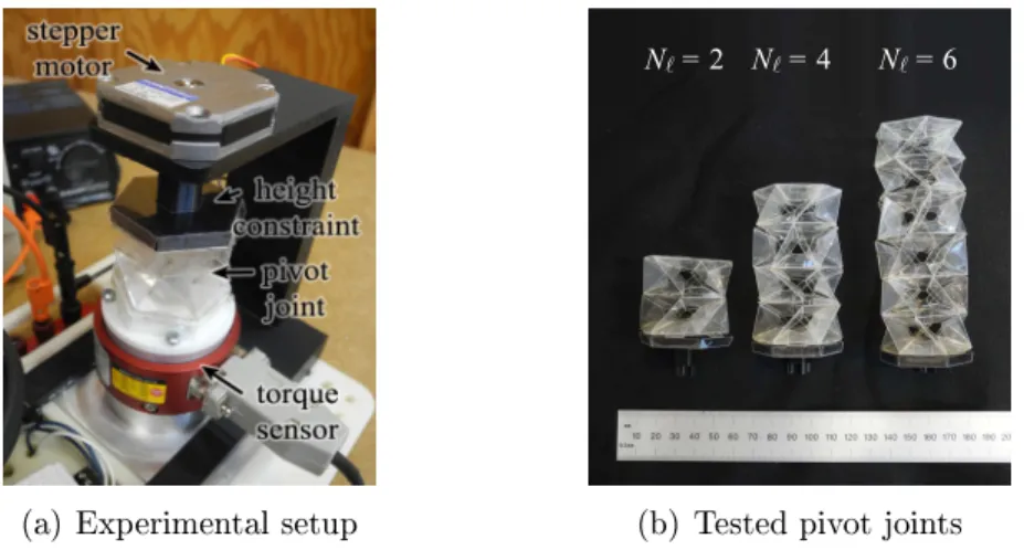
4-12 Experimental setup used to measure holding torque of hinge joints . . 58
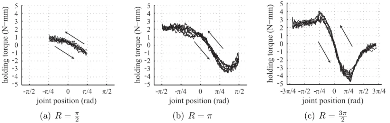
4-13 Holding torque vs. joint position for hinge joints folded from 0.051 mm thick polyester film, with joint ranges 𝑅 = 𝜋 2, 𝑅 = 𝜋, and 𝑅 = 3𝜋 2 . . . 59
4-14 Holding torque vs. joint position for hinge joints folded from 0.127 mm thick polyester film, with joint ranges 𝑅 = 𝜋 2, 𝑅 = 𝜋, and 𝑅 = 3𝜋 2 . . . 59
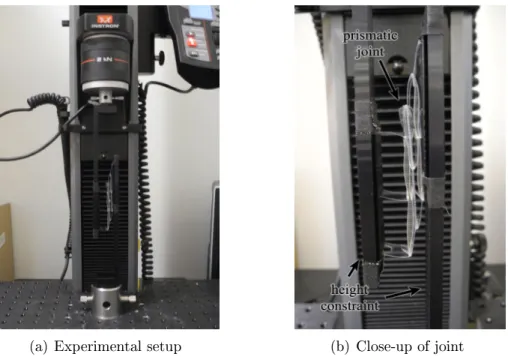
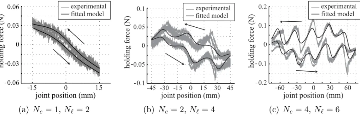
4-15 Experimental setup used to measure holding force of prismatic joints 60 4-16 Holding force vs. joint position for prismatic joints folded from 0.051 mm thick polyester film, overlaid with curves fitted from the model . . . . 61
4-17 Holding force vs. joint position for prismatic joints folded from 0.127 mm
thick polyester film, overlaid with curves fitted from the model . . . . 61
4-18 Experimental setup used to measure holding torque of pivot joints . . 62
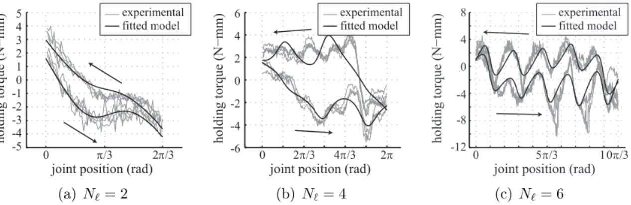
4-19 Holding torque vs. joint position for pivot joints folded from 0.051 mm thick polyester film, overlaid with curves fitted from the model . . . . 63
4-20 Holding torque vs. joint position for pivot joints folded from 0.127 mm thick polyester film, overlaid with curves fitted from the model . . . . 63
5-1 Fold pattern composition problem illustration . . . 66
5-2 Algorithm 2 step-by-step example . . . 71
5-3 Algorithm 3 step-by-step example . . . 73
5-4 Intersection removal in Algorithm 2 . . . 73
5-5 Trimming of long pleats for Algorithm 2 . . . 74
5-6 Algorithm 4 step-by-step example . . . 75
5-7 Example edge-adjacency graph . . . 76
5-8 Two convex polygons placed next to each other are guaranteed not to intersect . . . 78
5-9 Edge-compositions of rigid bodies, fold patterns, and physical models 86 5-10 Spherical joint composed from 6-sided pivot and hinge joints . . . 88
5-11 Foldable four-bar linkage . . . 89
5-12 Foldable rowboat . . . 90
5-13 Actuated four-bar linkage atop actuated pivot mount . . . 91
5-14 Smartphone mount attached to actuated spherical joint for pan and tilt 92 6-1 Joint controllers for single-link leg, multi-link leg, and wheel joint types 97 6-2 Relevant points along a robot’s trajectory used in metric evaluation . 101 6-3 3-D mesh generation procedure for robot bodies . . . 104
6-4 Printable, snappable connections used in 3-D mesh generation . . . . 105
6-5 Six robots designed and fabricated using composition . . . 107
6-6 Comparison of monkey gait in simulation and in physical robot . . . . 107
6-8 Other robot designs achievable using our design system . . . 109
6-9 Optimization results for a four-legged fish robot when maximizing speed or minimizing wobbliness . . . 110
7-1 A robot design that topples while walking. Its gait can be modified so that it only wobbles slightly, but changing the geometry allows the robot to move faster and more steadily. . . 114
7-2 Interactive design tool system diagram . . . 115
7-3 User interface for interactive design tool . . . 115
7-4 Geometry modules in the database, organized by category . . . 116
7-5 Data representation for geometry modules in the database . . . 117
7-6 Dimension scaling in the user interface . . . 118
7-7 Highlighted patch pairs proposed for connection . . . 119
7-8 Gait design interface . . . 121
7-9 Guidance arrows for local geometry optimizations . . . 123
7-10 Cars designed by 8 different users after a 20 min. training session with the tool. Users were given 10 min. to design their car. . . 125
7-11 Gallery of designs created by one of the users in the user study after a 20 min. training session. Each of the designs took between 3 and 25 min. to design and contains multiple modules from the database. . 126
7-12 Trajectories designed by users during task 2 of the user study . . . . 126
8-1 Multi-layer process for fabricating medium-scale rigid robot bodies . . 132
8-2 Layers for an example fold pattern fabricated using our multi-layered approach . . . 133
8-3 Side view of two faces of thickness 𝑡 that come together at a fold with angle 𝜑 between them . . . 134
8-4 Teeth structure for a pair of edges that form a fold . . . 136
8-5 Wide hexapod cut out of 3.18 mm thick acrylic sheet using our multi-layer fabrication process. . . 137
8-6 Long hexapod cut out of 4.50 mm thick acrylic sheet using our
multi-layer fabrication process. . . 137
8-7 Hexapods cut from thick material next to print-and-fold hexapod . . 138
8-8 One cycle in the walking gait of the wide hexapod . . . 140
8-9 Cut pattern for folds on a metal robot . . . 141
8-10 Large metal robot designed in system and folded from aluminum sheet 142 A-1 Fabricated moving house robot, left and right views . . . 151
A-2 Generated print for fold pattern of the moving house . . . 152
B-1 Obstacle course used in task 2 of user study . . . 168
List of Tables
3.1 Symbols pertaining to fold patterns . . . 39
3.2 Symbols pertaining to foldable joint designs . . . 40
3.3 Symbols pertaining to robot design . . . 40
3.4 Symbols pertaining to robot performance metrics . . . 41
3.5 Symbols pertaining to fabrication . . . 41
4.1 Fitted fold stiffness values 𝑘 for prismatic joints made from two thick-ness of polyester film . . . 62
6.1 Comparison of measured vs. simulated metric values . . . 108
6.2 Fabrication time and material usage for 3-D printing (3-D) vs. print-and-fold (2-D) . . . 111
7.1 Timing data from task 3 of user study where users optimized a design with and without feedback . . . 128
8.1 Specifications for medium-scale hexapod robots . . . 138
8.2 Timing per step of fabrication . . . 139
List of Algorithms
1 Compose((𝑃1, ℱ1), 𝑒𝑃1, (𝑃2, ℱ2), 𝑒𝑃2) . . . 70 2 BridgeFromBoundary((𝑃, ℱ), 𝑒𝑃) . . . . 71 3 CreatePleats(𝑒𝑃, p). . . . 72 4 BridgeFromFoldLine((𝑃, ℱ), 𝑒𝑃) . . . . 75 5 Simulate(D, ∆𝑡) . . . 100Chapter 1
Introduction
A long-held goal in the robotics field has been to see our technologies enter the hands of the everyman. With the emergence of retailers such as Pololu [138] and Adafruit®[2], as well as products such as the iRobot®Roomba®[81] vacuum cleaner,
this goal has recently started to become a reality. Despite these advances, customizing robotic technology to individual needs remains a challenge. Robots are complex systems that tightly integrate mechanical, electronic, and computational subsystems. As a result, customization at anything more than a superficial level often requires a nonnegligible amount of engineering skill. And yet, in order for robots to be able to address the individual needs of their users, they must allow for personalization.
Traditionally, robot development is a challenging and time-consuming process involving many iterations of design and testing, even for skilled engineers. Designers who decide to tackle this challenge must be able not only to devise and integrate physical and computational subcomponents, but also to evaluate manufacturability, usability, reliability, and other practical issues. With a required knowledge base this large, it should be no wonder that such projects often go through multiple prototypes before converging to a final design.
Given this design paradigm, a natural question is: Is it possible to simplify design evaluation, cut down on the number of prototyping cycles, or otherwise make the de-sign process more accessible? The answer from a hardware perspective is a resounding yes. Recent advances in rapid fabrication [88, 201] have made creating complex 3-D
physical objects easier than ever, allowing people to realize their designs in hours or days instead of weeks or years. Unfortunately, when it comes to evaluation and design cycles, current design tools still present users with clear limitations, and the learning curve is steep for anyone who wishes to create a design from scratch.
In this thesis, we explore intuitive design tools that complement current rapid fabrication methods, with the goal of providing all roboticists, from dabblers to skilled professionals, with a framework for rapidly exploring, evaluating, and realizing their robotic designs. The tools incorporate simulations and interactive feedback with algorithms for design automation to streamline parts of the design cycle and give users the information they need to make design choices. We focus in particular on foldable robots, robots whose mechanical parts are fabricated as flat sheets and folded into their final 3-D form. As we will show, creating robots in this way accelerates the fabrication process and enables us to construct strong and lightweight structures well suited for robot designs, but it also presents additional fabrication constraints that complicate the design process. We tackle this challenge by proposing a design-by-composition approach to foldable robot design. In this approach, modules are composed together to form entire mechanisms and robots, and the validity of the design is maintained at every step. The approach not only finds practical use in an interactive design tool, but also provides insights into the space of feasible foldable designs.
1.1 New Capabilities
The results of this thesis will give rise to new capabilities for robot creators.
Exploratory Tools Tools that provide intuitive interfaces for creating and analyz-ing designs lower the cost of design exploration. In addition, analyzanalyz-ing users’ designs before prototyping allows them to explore many different choices and find potential issues early before committing to a particular design. Since the effect of early design choices on a final product’s performance is large compared to later choices [79], early
exploration of the design space is a valuable ability with the potential to significantly decrease time spent in later parts of the design process.
Rapid Iteration and Prototyping Tools that incorporate manufacturability con-straints accelerate design iteration by decreasing the time to prototype. While ad-vances in additive manufacturing have significantly increased prototyping capabilities, they suffer from a lack of corresponding design and modeling tools. The ability to de-sign specifically for a fabrication technology will allow dede-signers who otherwise would have had to wait weeks or months to finish a physical prototype to quickly evaluate their designs and make important design choices or changes.
Educational Tools Intuitive design interfaces provide valuable learning tools to novice engineers. Real-time design analysis and interactive feedback provide users with relevant information necessary to evaluate different design choices and to see how changes to the design affect its performance. Further, the ability to rapidly fabricate these designs allows engineering students to quickly receive real-world feedback about their robots while their design choices are still fresh.
Customized Technology Accessible design tools lower the barrier to entry to robot design. As a result, aspiring designers who are not trained in engineering will still be able to make the necessary design decisions and trade-offs to create customized robotic technologies to use in their own lives.
1.2 Challenges
The main challenge with robot design is that the design space is large, and there is a great amount of flexibility. Take, for example, the task of designing a robot to perform the simple locomotion task of moving across an empty room. There are many different robots that could do this task: cars that roll across the floor, legged robots that walk, robots that hop from one side of the room to the other, robots that fly, robots that slither, or robots that engage in myriad other possible types of locomotion. Further,
for each of these types of robots, the particular robot could take on any number of forms. A robot design tool must allow users to make interesting design choices while presenting the design space in an intuitive and manageable manner. In this thesis, we address this problem using a design-by-composition framework.
A second challenge is the interdependence of subsystems in a robotic design. Con-sider again the robot that must move across a room. The robot has a mechanical body that has a geometry, has a particular kinematic structure, and is made of certain ma-terials; it has actuators, sensors, and electronics that control the robot’s interactions with the environment at the low-level; and it has software that provides its high-level behaviors. Each of these components affects the other. For example, the mechanical body affects the actuator requirements and the efficiency of the programmed behav-iors, while the electronics and software induce geometric and control constraints. A robot design tool must simultaneously consider these subsystems and allow users to explore how changes to one aspect of a robot design effect changes in another. In this thesis, we address the subproblem of geometry-motion interdependence.
A third challenge is the transition from a conceptual design to a physical robot. Any design that a user creates must be manufacturable, that is, each of its pieces must be able to be fabricated, and the disparate pieces must be able to be assembled. Therefore, a robot design tool should validate not only a robot’s final form but also its fabrication plan. In this thesis, we address manufacturability in the context of foldable robots. In order to create foldable robots, designs must be able to be fabricated as 2-D fold patterns, a constraint that introduces its own set of challenges. In addition, transformable folded structures (i.e., folded structures that can move), which are the structures of interest for robot designs, are not well understood. We explore what kinds of robotic designs can be assembled by folding and, in the context of design by composition, composed into more complex patterns.
1.3 Design by Composition
Our approach to tackling these challenges is to use a design-by-composition frame-work. In this framework, users create entire robots by composing modules from a database of parameterized designs. The database focuses the design space to a set of designs that are manageable for a computational tool, while the parameterization of individual modules provides users with enough freedom to express themselves cre-atively [57]. In addition, the designs in the database, which can be augmented by experienced designers, provide users with proven examples with which they can build future designs.
Design by composition also tackles the second challenge of concurrent subsystem design. The main challenge of composition is that even when modules are individually valid, their combination may not be a valid design. We include both geometric- and motion-related modules in the database, and we incorporate simulations and opti-mization methods that evaluate design performance in the context of both geometric and motion data. As users compose modules from the database, constraints on the module parameters that result from the composition are automatically associated with the design. Our evaluation and optimization methods use the module parame-terizations and composition constraints to allow users to automatically optimize over multiple aspects of the robot design.
Finally, design by composition addresses the third challenge of manufacturability. We ensure that every module in the database is independently manufacturable for any set of parameter values in the feasible set of the design. By developing methods for module composition and parameter manipulation that maintain manufacturability, composed designs are automatically manufacturable as well.
1.3.1 Scope and Limitations
As with any data-driven method, a design-by-composition approach restricts the pos-sible output designs to those that can be composed from the database. Experienced
designers are needed to expand the set of building blocks from which users can com-pose their own designs.
In addition, this thesis addresses composition of only geometry and motion mod-ules. Expanding this work to include other aspects of robot design requires introduc-ing new composition algorithms to handle the new types of design constraints, as well as new simulation and evaluation capabilities.
Our design tool is driven by the user, who chooses modules from the database to compose. Optimization methods built on top of this tool can provide feedback about parameter changes, but not about module changes. Users can explore how the simulations and evaluations change as they add and remove parts manually.
Finally, this thesis focuses on foldable robots, and our database contains only foldable designs. Although the composition algorithms and data representation de-scribed are particular to folding, however, the underlying methods can be generalized to other fabrication methods. Augmenting this work to allow other fabrication meth-ods requires new analysis of the constraints associated with those methmeth-ods, as well as new composition algorithms.
1.4 Thesis Contributions
This thesis makes the following contributions:
A design-by-composition framework for foldable robots. We present a framework for robot design by composition, in which modules from a database of foldable designs are composed into full robots. The approach incorporates new foldable modules that enable a wide variety of robot kinematics, algorithms for geometry and motion composition, simulations and optimization methods for evaluating composed designs, and methods for automatic fabrication of the results.
A database of parameterized and foldable modules. We explore the space of possible motions achievable through foldable designs by creating
parameter-ized designs of foldable joints. We have analyzed these joints theoretically and verified their behavior through experiments on fabricated examples. Together with fold patterns for rigid bodies, the parts in this database can be composed to produce a variety of robot geometries and functionalities.
An algorithm for fold pattern composition. We detail an algorithm for combining two fold patterns into a new one-piece non-self-intersecting compo-sition consisting of the two originals attached at an edge. The algorithm is guaranteed to produce a valid output fold pattern. It runs in time polynomial in the number of vertices in the original patterns and adds a polynomial amount of extra waste material. We also show how the algorithm can be augmented to compose patterns at faces instead of edges.
Grammar-based gait suggestion for ground robots. We have imposed a classification of ground robot parts into bodies, legs, wheels, and peripherals, and we use this classification to propose a grammar-based gait for composed designs. Individual joint motions for a composed robot are suggested based on the types of modules connected at that joint. We demonstrate these gaits on a variety of composed robots.
Algorithms for automated generation of fabrication plans. We describe methods for converting user-specified 3-D designs into valid fabrication plans. We have addressed a variety of origami-inspired methods for fabricating me-chanical components at a variety of scales. We also describe an approach for converting designed gaits into electronics and software components.
An interactive end-to-end system for compositional robot design. We have created an interactive tool in which users can manipulate and compose modules from the database to create custom ground robots. The tool incor-porates the algorithms in this thesis to produce functional designs with valid fabrication plans. We have conducted a preliminary user study with the tool
and determined that users found interacting with the tool to be both intuitive and enjoyable.
Robot designs fabricated at multiple scales. We have used the proposed framework to design and create robots ranging in size from 146 mm long to 620 mm long and fabricated using a variety of techniques. The robots are all demonstrably functional. Our results show that the design-by-composition framework has the potential to scale to many different applications.
1.5 Thesis Organization
The remainder of this thesis is organized as follows. In Chapter 2, we compare our work to previous research in rapid fabrication, design methods, and origami-inspired robotics. In Chapter 3, we present important notation and symbols used in the thesis. In Chapter 4, we describe our foldable joint designs and their analysis. In Chapter 5, we discuss fold pattern composition and describe an algorithm for composing two fold patterns at an edge. In Chapter 6, we describe our grammar-based approach to gait suggestion for ground robots, our metrics for evaluating these gaits, and methods for converting these gaits into electronics and software. In Chapter 7, we describe an interactive tool that we have developed to aid casual users in composing foldable robot designs and a user study we conducted with the tool. In Chapter 8, we describe several results incorporating other fabrication approaches. We conclude and discuss directions of future research in Chapter 9.
Chapter 2
Related Work
This thesis is enabled by technical advances in the fields of rapid fabrication, compu-tational design, and origami-inspired engineering, as well as by techniques in design composition. In this chapter, we outline previous results in the literature to set the context of our work.
2.1 Rapid Fabrication
With the growing interest from hobbyists and makers in creating custom robots and mechanisms [18, 56], there has been a corresponding boom in rapid fabrication and prototyping capabilities. Among these, 3-D printing has emerged as a convenient method for creating general geometries quickly. Unlike traditional manufacturing, in which complex geometries require in-depth analysis to ensure fabricability [70], 3-D printing processes are independent of the fabricated object, meaning that designers are now able to instantiate increasingly complex geometries without corresponding increases in cost or fabrication time. The most common methods for printing 3-D geometries are fused deposition modeling, in which spools of thermoplastic filament are melted and fused into layers of the fabricated solid object, and stereolithography, in which liquid material is cured using ultraviolet light and merged to form the object layers. A review of existing 3-D printing technologies can be found in [61,201].
As a result of these technologies, multiple groups have started to investigate how mechanisms and linkages can be fabricated as single prints without requiring post-fabrication assembly. Work in [9,24] explored a wide variety of printed joint designs, including universal and spherical joints, that could be used in full mechanisms [180], manipulators [107], and robots [110, 162]. Fuge et al. [56] expanded on this body of work by including methods for automated calibration of joint designs to the fabrica-tion machine. Multi-material printers have further increased the diversity of printed objects by allowing designers to control properties such as stiffness [78], damping [105], and texture and transparency [27,189], giving them the ability to print such functional objects as flexure hinges [41,63], hydraulic drive systems [104], and full robots [72].
2.1.1 Origami-Inspired Fabrication
Although recent advancements in machining practices and 3-D printing technology have produced significant speedup in manufacturing of mechanical structures, these methods are still costly and time consuming when compared with planar fabrica-tion alternatives [132]. Origami-based design methods aim to augment existing 2-D fabrication techniques with folding algorithms to rapidly fabricate 3-D structures. Fabricating structures in plane and then folding them into their final shape enables complex devices to be created more quickly and efficiently, providing engineers with greater opportunities to prototype, test, and refine their designs.
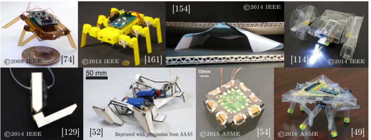
Folding in engineering design has existed in mechanical designs for decades [179, 184] and more recently is being applied to electromechanical devices and foldable circuits [71, 131, 157]. The ability to integrate sensors and circuitry directly into the physical body of a device has enabled the creation of fully functional robots in less than a day [53, 74, 132]. In addition, folding thin materials can create strong, lightweight components, which are ideal for robot designs [127, 161]. Folding as a vehicle for physical change has given rise to sheets with programmable shape [71], manipulators [46,58,155,167,198,205], sensors [122,156], and support structures that precisely assemble small devices [197]. The transformation abilities of assembled folded structures have also been used to control how a robot crawls [44, 52, 54, 89],
[74]
©2008 IEEE ©2013 IEEE [161]
[154] ©2014 IEEE
[114] ©2014 IEEE
[129]
©2014 IEEE [52] Reprinted with permission from AAAS ©2015 ASME [54] ©2016 ASME [49]
Figure 2-1: Previous foldable robots
jumps [50], or navigates obstacles [97]. Figure 2-1 shows some previously developed foldable robots.
In its most basic form, origami-inspired fabrication consists of cutting thin sheets of flexible material, such as paper or plastic, and deforming them into a 3-D shape. This method is often used when creating simple models [203] or paper toys [66, 120, 147, 177]. Stiffer designs can be created by laminating layers of different materials and cutting away parts of individual layers to create a structure combining both rigid and flexible parts [73, 74]. The approach has been used with great success to create folded structures with up to 15 layers [197] that assemble and self-align similarly to pop-up books, but it requires more complex methods for converting fold patterns into fabrication plans that take into account the thickness of the materials used [29, 93, 175]. Still more complex models can be created through a combination of additive manufacturing and folding, as shown in [40], where multi-material printers provided the designers with a simpler solution to mixing material properties to produce foldable structures.
The benefits of origami-inspired fabrication are tempered by the complexity of subsequent assembly steps. Folded structures often present more complex fabrication plans than the equivalent structure made through traditional 3-D manufacturing. As a result, many groups have also been searching for ways to automate the assembly of folded structures. For example, work in [12, 178] used a robotic manipulator to
fold origami patterns from a sheet of paper. Later, work in [124] took advantage of heating and gravitational forces to show how plastic sheets heated along a fold line could deform into a folded shape naturally. Work in [16, 28] bypassed the folding problem completely by cutting planar faces individually and assembling them using custom connectors.
Other approaches to automated folding focus on incorporating folding information into the structure itself. These “active origami” structures [137] rely on active materi-als to fold and unfold a pattern. The advantage of these approaches is that the same infrastructure used for assembly can also be used for actuation during operation [53]. Programmable sheets [4,71] encode generalized crease patterns with the ability to fold into arbitrary voxelized shapes using shape-memory alloys (SMA). Instance-specific approaches have also emerged, producing a variety of designs that fold using residual stress [13, 202], heat [41, 52, 53, 64, 90, 122, 182, 183], exposure to water [69, 154, 155], air pressure [129], and magnetic fields [84, 103, 204], particularly in the creation of microscale structures.
In this thesis, we primarily fold mechanical structures out of sheets of a single material, although we show extensions to other fabrication methods as well.
2.2 Computational Design of Robots and Functional
Mechanisms
The incredible growth of rapid fabrication technology has incited a corresponding growth in design algorithms and tools. Approaches to design can be categorized into fully automated methods and interactive methods.
2.2.1 Fully Automated Design
Fully automated methods for robot design aim to create entire designs with min-imal user intervention. These problems are generally formulated as optimizations over design and function parameters. In certain cases, the form of the robot is well
specified [42, 134, 191], and optimization methods are used to ensure efficiency. In other branches of work, users specify less about the robot. For example, work in [25] considered the robot design problem as a set of constraints on inputs, outputs, and inter-component dependencies, and it chose the components such as motors and chas-sis that satisfied the problem. It did not consider how the physical components should be connected. Work in [75,158,159], by comparison, focused on the physical structure over the actuation and used genetic algorithms to generate virtual linkage designs to perform various tasks such as locomotion and manipulation. The work was extended to fabricated robot designs in [30,99].
The difficulty of designing entire robots from scratch has caused many research efforts to focus on automated design for particular subsystems and goals. For ex-ample, work in [82] considered modular robot design from a task perspective. A high-level task was broken down into a sequence of subtasks that were matched to existing full designs in a database, and transitions between subtasks occurred through reconfiguration. Motion plans were the subject of [92], which used linear temporal logic specifications to define high level task requirements and search for valid plans given a robot model and environment. Motion of a linkage mechanism was consid-ered in [85, 87]. This work proved that there always exists a linkage able to follow a bounded subset of an algebraic curve and showed how to construct one. Finally, there exist systems that focus on fabrication aspects, such as those that automatically choose materials given desired properties [20, 27, 189] or that optimize geometry to account for particular fabrication methods [28,100,102].
2.2.2 Interactive Design
Compared to software compilers, or even work on automatic circuit design [126], fully automated mechatronic design systems have not gained wide acceptance in the en-gineering community. Progress on this front has been slowed by the high amount of coupling between different subcomponents of the same system [5,51,193,194]. There-fore, more recent systems have been turning towards interactive design approaches that require more user input in the design process.
Interactive tools have been useful in designing a variety of physical objects, includ-ing architectural structures [190, 196], urban spaces [188], furniture [91, 96, 149, 152, 185], statuettes [128,140], clothes [109,186], toys [11,123,160,166,187], pop-ups [6,7], and general geometries [59,151]. This success has encouraged their use for mechanical assemblies as well. Previously, systems such as those in [48, 163] used textual inter-faces to ask users a series of questions and produce linkages based on required inputs, outputs, and degrees of freedom. These systems used targeted queries to narrow down the space of designs to present to users. Since Mitra et al. proposed visual cues for mechanical assembly visualization in [121], multiple graphical tools have emerged for designing other types of mechanisms, including cam mechanisms [207], gear sys-tems [34], linkages [10, 180, 206], and walking automata [19]. Reconfigurable objects such as furniture [62] and fold patterns [67, 80] have also been treated to not only analyses of their motion, but also checks for stability, collisions, and structural prop-erties. The designed objects can be fabricated with various rapid fabrication methods by using complementary interactive tools that allow users to specify the fabrication method [16,125] or object stiffness [200], and that break down the designs into parts that can be individually manufactured and assembled [101].
More recently, interactive approaches to design have been applied to robots and other mechatronic systems. Tools such as those in [17,143] have aimed at addressing electromechanical constraints and producing user-customized but verifiable electron-ics plans. Simple programming interfaces integrated into the system allowed users to check their proposed connections against simulated behavior. Work in [111, 112] extended these methods to robot designs, allowing users to generate combined me-chanical and electronic designs. Work in [45,110] further added simulations enabling users to visualize robot behavior.
These existing tools provide users with the ability to specify designs but provide little guidance to users during the design process. In this thesis, we leverage a pa-rameterized database to enable this feedback, allowing users to explore how design changes affect the simulated performance to produce more effective interactions.
2.3 Design by Composition
Simplifying design by composing existing modules is an approach that has been pro-posed for robot hardware before. Modular robots are systems of identical functional modules that can be connected together in various ways to form robots with complex functionalities [165]. Multiple types of modular robot hardware have been devel-oped [22,37,65,116,144–146,164,195], but these systems have suffered from the idea that all modules must be the same. While using identical modules for all parts of a robot increases versatility and robustness, it also vastly increases the complexity requirements for individual modules.
An alternate approach is to compose modules of different types, each with their own intended functionality. In engineering practice, complex systems are commonly designed by breaking them down into smaller components that are matched to build-ing blocks in a knowledge base [26, 32]. Systems such as Topobo [142], LEGO®
Mindstorms® [68], and Fischertechnik® [55] emulate this process by providing users
with existing hardware pieces that they can snap together to create interesting new designs. Parameterizing the pieces so that they can also be customized on the fly has proven to be an effective strategy for computational tools to provide users with cre-ative freedom while maintaining a simplified design process [57]. As a result, design by composition has been used for such objects as furniture [91, 152], puppets [26], clothing [109], and electromechanical systems [17].
In robot control, composition of motion primitives is also an effective strategy for producing complex high-level behaviors and is often combined with hierarchical control. Work in [130] applied this approach to a hexapod robot, using a high level controller to determine the parameters for individual controller modules at each of the joints. Work in [181] used a similar approach for a manipulator arm, but rather than controlling individual joints, it used a low-level controller to decrease the effective dimensionality of the system and a high-level controller to set the values of this smaller set of parameters.
Systems that leverage a design-by-composition approach not only simplify the design space but have also been shown to facilitate rapid fabrication. For exam-ple, in [106], an automated pick-and-place machine was used to assemble a carefully chosen set of electromechanical building blocks. Similarly, in [111], a composition approach was proposed for foldable robot design that automatically generated the fold pattern for the robot body, although no guarantees or analysis of the designs were provided. In [45], existing hardware was combined with 3-D printed joints and freeform components to create customized multicopters that achieved stable flight. At a smaller scale, composition of microstructures in 3-D printing allows digital fab-rication methods to produce material properties not achievable through solid blocks of a single material alone [27,189].
In this thesis, we explore design of foldable robots by composition, as well as algorithms and analysis methods that can be incorporated into the design process to produce robots of guaranteed validity.
2.4 Origami-Inspired Engineering
Origami-inspired fabrication approaches introduce additional complexity to the design process. In particular, fabricated objects must have valid fold patterns. For static objects, this is a well studied problem, while questions about transformable structures remain largely unanswered.
2.4.1 Static Structures
The problem of edge-unfolding polyhedra involves flattening a polyhedron by cutting along some of its edges and unfolding the rest (See [39] for a survey of results). The resulting planar figure should be a simple, non-overlapping polygon. A number of algorithms have been proposed for approaching this problem (ref. [150]), although none succeed in the general case. Since the traditional problem statement for edge unfolding requires that every face be covered exactly once and that no extra material be added, there exist polyhedra such as that in [15] for which an edge unfolding
does not exist. As a result, some heuristics [120,177] have been developed that allow multiple pieces to be used or minor changes to the 3-D geometry to be made.
In contrast, extra material can be added in origami design problems [94, 95, 173], where an arbitrary polyhedral surface is folded from a convex 2-D sheet of paper. Work in [148] characterized these types of fold patterns and provided necessary con-ditions for the patterns to be foldable, and systems in [67, 80] provided methods for users to design, simulate, and visualize new fold patterns. Algorithms for auto-matically constructing designs have been proposed on multiple fronts. In [173, 174], arbitrary simple polyhedral surfaces were converted into origami designs by position-ing faces of the surface on the 2-D plane and tuckposition-ing away excess material to brposition-ing neighboring faces together. Composition of origami designs is an idea that appeared in [117, 118], in which rotational symmetry allowed the goal surface to be decom-posed into slices, each of which could be achieved by the same fold pattern. Similarly, Cheng and Cheong [31] decomposed a surface into horizontal slices and construct its unfolding one level at a time. Both of these algorithms were limited in the types of surfaces that they could produce.
In practical design, additional constraints also have to be met. For example, objects folded from sheet metal have constraints on bend radius or design complex-ity [35]. To deal with these constraints, work in [23] proposed a multi-stage approach for generating a sheet metal part that covers all user-specified regions while avoid-ing user-specified obstacles. In [135, 136], the authors solved a similar problem and enforced manufacturability of the part by generating only designs that could be pro-duced using a set of allowed sheet metal operations. In both of these cases, the user inputted only constraints on what should or should not be covered, but the actual shape of the part was left to the algorithm, allowing greater flexibility to reduce cost and manufacturing time. Wang [192] considered the case where the desired shape of the sheet metal part was entirely known. When the shape was not manufacturable as a single piece, then it was decomposed into simpler manufacturable components that could be assembled via welding, riveting, etc.
2.4.2 Transformable Structures
For foldable robots, it is desirable that fold patterns produce mechanisms, that is, structures that move. Unfortunately, the space of transformable folded structures is not well characterized. Exploration of transformable folded structures seems to have been limited to single designs that are created by individuals (ref. Section 2.1.1) are are difficult to generalize. Progress beyond these structures is complicated by a lack of understanding of what types of motions can result from folding. The most promising results have come from the study of pop-ups. For example, algorithms proposed by [1] demonstrated how to design pop-ups for general polygons, and work in [98,119] tackled automated pop-up design for models of buildings. Pop-up mechanisms were analyzed and categorized in [199], and the results were used to propose new pop-up joint types. In contrast, a similar analysis of general folded designs as spherical mechanisms was performed in [21], but although many models from popular literature were classified, no new principles were derived or new mechanisms found.
A small set of parameterized transformable designs can be found in the literature. For example, work in [60] proposed a new rotational joint type that can be composed into closed loops of arbitrary size. A collapsible wheel was proposed in [97] to enable robots to shrink in height and roll under obstacles. A continuously foldable cylinder that could be tessellated to produce cellular structures that expand and contract was demonstrated in [176], and work in [133] showed a 3-D analog with three degrees of freedom. Work in [86] demonstrated a pattern based on the Kresling pattern for controlling not only the shape but also the stiffness of cylindrical structures. Finally, work in [49, 113] suggested methods for combining designs for parameterized rigid robot body parts to form entire robot designs.
Although these pieces of work present interesting new degrees of freedom for robots, none of them systematically explores the foldable mechanism design space. In this thesis, we propose parameterized joint designs for joints commonly used in robot designs, as well as methods for them to be combined to create more complex joints and full mechanisms.
Chapter 3
Notation
This chapter provides a brief summary of the notation and symbols used in the thesis. Chapters 4 and 5 are primarily concerned with fold patterns. Briefly, a fold pattern (𝑃, ℱ ) consists of a non-self-intersection 2-D polygon 𝑃 and a set of folds ℱ. Each fold 𝑓 ∈ ℱ is a line segment on the interior of 𝑃 and is associated with a fold angle. The 3-D shape that results from bending the fold pattern at each of the folds is called the folded state. The following symbols refer to properties of a fold pattern or a folded state.
Table 3.1: Symbols pertaining to fold patterns Symbol Definition
(𝑃, ℱ ) A fold pattern consisting of a polygon 𝑃 and a set of folds ℱ 𝑒 An edge of an unfolding (𝑃, ℱ)
𝑓 = (𝑒, 𝜑) A fold consisting of a fold line 𝑒 and a fold angle 𝜑 ℰ(𝑃, ℱ ) Edge set of the fold pattern (𝑃, ℱ)
𝒱(𝑃, ℱ ) Vertex set of the fold pattern (𝑃, ℱ) 𝑁 Number of vertices
𝑀 Number of edges
CH(𝑃 ) Convex hull of the polygon 𝑃
𝑄 Polyhedral complex, image of a folded state ℰ(𝑄) Edge set of the polyhedral complex 𝑄 𝒱(𝑄) Vertex set of the polyhedral complex 𝑄
Additionally, Chapter 4 presents foldable rotational and translational joint designs and a model of the mechanics of the proposed designs. The following symbols are relevant to these joints.
Table 3.2: Symbols pertaining to foldable joint designs Symbol Definition
𝑅 Joint range of motion 𝑁𝑠 Number of sides of joint
𝑁ℓ Number of layers of joint
𝑟, 𝑟𝑖, 𝑟𝑜 Radius, inner radius, and outer radius of rotational joints
𝑑, 𝑤, ℎ Depth, width, and height of one segment of prismatic joint 𝑘𝑖 Stiffness of fold 𝑖
𝜃 Rotational joint angle
𝜏𝜃 Holding torque required to maintain joint at angle 𝜃
𝑥 Prismatic joint position
𝑅𝑥 Holding force required to maintain joint at position 𝑥
Chapters 6 and 7 discuss designing robots within the composition framework. A robot design D consists of a hierarchy of connected modules with geometric parame-ters q and gait parameparame-ters 𝜃𝑖 and 𝑔𝑖. The robot designs are evaluated by discretizing
time, iterating through a sequence of rigid body simulations, and repeating the gait until the robot reaches a steady state behavior. The following symbols refer to a robot design and the parameters related to its geometry, gait, or simulation.
Table 3.3: Symbols pertaining to robot design Symbol Definition
D Robot design
q Geometric parameters of a robot design 𝑄 Feasible set for parameters of a robot design 𝑁𝑔 Number of steps in a gait
𝑔𝑖 Step parameter for limb 𝑖 in a gait
𝜃𝑖 Angle parameters for limb 𝑖 in a gait
∆𝑡 Time step used for robot simulation
c𝑖 Contact points of robot with the ground at time 𝑡𝑖
𝑡𝑖0 Start time for robot steady state behavior
Our system evaluates multiple performance metrics during the simulation and reports these metrics to the designer. The following symbols are the relevant variables and metrics used.
Table 3.4: Symbols pertaining to robot performance metrics Symbol Definition
x(𝑡) Position of robot center of mass projected on ground at time 𝑡 ˜
x(𝑡) Expected position of robot at time 𝑡 given a circular trajectory 𝑆 Stability (mm)
𝑉 Velocity (mm/s) 𝑊 Wobbliness (radians)
∆𝛾 Combined pitch-roll angular change (radians) 𝐸 Slip (mm)
𝜙 Heading (radians) 𝜌 Curvature (1/m) 𝜎2 Variance (mm2)
Finally, Chapter 8 discusses alternate fabrication methods. The following symbols refer to variables used in the generation of the fabrication plans for these methods.
Table 3.5: Symbols pertaining to fabrication Symbol Definition
𝑡 Thickness of material used
ℓ𝑖, ℓ𝑜 Inner and outer positions for teeth generation along a fold
Chapter 4
Transformable Foldable Modules
In a design-by-composition approach, a key element is the modules that make up the database. For robots, those modules must consist of both rigid components and movable joints. However, as discussed in Chapter 2, transformable folded structures have not been well studied, and the space of transformable foldable designs remains uncharacterized.
In this chapter, we address the question of what motions are achievable through folding, and we contribute fold patterns for revolute and prismatic joints that are parameterized to achieve a user-specified size and range of motion. The designs provide users with greater flexibility in fold pattern design compared to previous modules [60, 113]. Since the joints are meant to be used in foldable robots, all of the designs provide natural attachment points for other modules, as well as space for actuators. We have fabricated our joints and compared their force-displacement curves to a pseudo-rigid-body model [77]. Together with rigid shapes, these joints form a base set of modules from which robots with any desired kinematics can be created out of a folded sheet.1
fold pattern (P, F) folded state unfolds into folds into fold line eP P fold angle φ
Figure 4-1: A fold pattern (𝑃, ℱ) consists of a polygon 𝑃 and a set of folds, each of which has a fold line and a fold angle. The pattern folds into a 3-D folded state.
4.1 Parametric Designs
Our mechanisms and robots are based on three joint types, a hinge joint, a prismatic joint, and a pivot joint. In this section, we present the parameterized fold patterns for each.
4.1.1 Definitions
We begin with informal definitions for the terms used in the following descriptions. A more formal treatment can be found in [39]. Consider a non-self-intersecting 2-D polygon 𝑃 , possibly with holes. A fold line on 𝑃 is a line segment such that both endpoints are on the boundary of 𝑃 and the segment itself lies on the interior of 𝑃 . A fold pattern (𝑃, ℱ) consists of such a polygon 𝑃 and a set of folds ℱ on 𝑃 . Each fold is a fold line associated with a fold angle in the range [−𝜋, 𝜋]. The folds in a fold pattern divide the original polygon 𝑃 into faces, smaller polygons that overlap only at the fold lines. The folded state is the 3-D shape resulting from bending the fold pattern to the given fold angle at each of the folds and keeping the faces flat (ref. Figure 4-1). The folded state must be non-crossing and should also be distance preserving (i.e., not stretch or tear the material).
When all fold angles are single values, then a fold pattern produces a static struc-ture. Positive fold angles correspond to what we common term valley folds, and negative fold angles are mountain folds. Since we are interested in patterns for joints,
which allow movement, some folds must be able to achieve entire fold angle ranges, which are connected subsets of [−𝜋, 𝜋]. We call these folds the active folds. In this thesis, figures depicting fold patterns will use the convention that active folds are drawn as solid lines, valley folds as dashed lines, mountain folds as dashed-dotted lines, and cut lines forming the boundary of 𝑃 as solid black lines.
Since the purpose of joints is to connect other structures to each other, our joints have faces that exist specifically to attach to other bodies. We call these faces the bases of the joint. All of our joints are designed to connect two structures to each other and so each have two bases.
4.1.2 Hinge Joint
Hinge joints enable rotation about an axis parallel to a base and can be implemented as a single active fold on the base itself. This is the approach taken in many previously designed foldable robots [49,113,161]. However, when hinge joints are created in this way, the joint itself consists of a single fold and occupies zero volume. As a result, the joint limits depend on the geometry of the bodies being connected and cannot be independently specified.
Joint description We have designed a hinge joint of a more general form, shown in Figure 4-2(a). The base of the joint is a regular polygon with 𝑁𝑠 sides (𝑁𝑠 = 6 in
R Ns
r
(a) Hinge joint
h R w d Nc Nl (b) Prismatic joint Ns ri ro R Nl (c) Pivot joint
Figure 4-2: Summary of fold patterns and folded states for three basic joint types with input parameters indicated. The base faces are shaded gray.
the example), where 𝑁𝑠 is even. From two opposite sides, sloped faces angle to meet
at the axis of rotation. Triangular faces are attached to all other sides of the bases to provide structural support.
When the joint moves, the top base rotates about the axis of rotation relative to the bottom base. The limits of the rotational motion are when two rectangular faces touch. Thus, the angle between a rectangular face and the base it is connected to is determined by the joint limits as 𝑅
4, where 𝑅 is the total desired angular range of
motion.
Fold pattern The associated fold pattern is a strip that attaches to the outer edges of the base polygons and contains the rectangular and triangular faces. Additional folds that tuck away extra material help form the hinge shape. Input parameters to the pattern are the number of sides 𝑁𝑠, the radius 𝑟 of the base, and the total
range of motion 𝑅. The basic hinge joint design is always symmetric. If asymmetric joint limits are desired, users can extend the base by attaching a sloped polyhedron and tilting the joint. Note that the joint angle is restricted to be between −𝜋 and 𝜋 radians, and that the length of the joint increases with the range of motion.
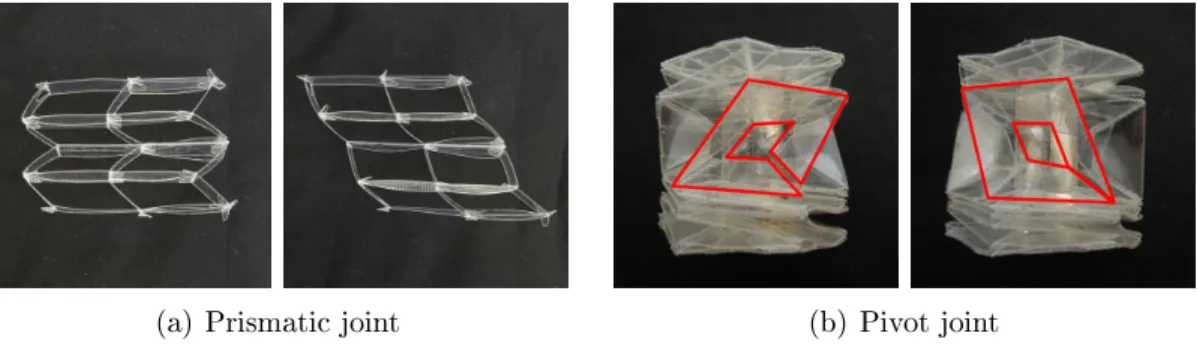
4.1.3 Prismatic Joint
Joint description A prismatic joint is created by composing parallelogram link-ages to produce linear motion of a desired distance without increasing the size of the joint. Each base of the joint is a rectangular face that forms one side of a parallel-ogram linkage. In a single parallelparallel-ogram linkage, horizontal and vertical translation are coupled. By connecting linkages in a grid, these two degrees of freedom can be decoupled. Figure 4-2(b) shows a two-by-two grid of linkages of height ℎ. By restrict-ing horizontal motion, the joint enables vertical translation by as much as 2ℎ. By restricting the vertical distance between the bases to be ℎ, the joint enables horizontal translation by a distance ℎ√3 in either direction.
The resulting structure enables 2 degree-of-freedom motion in a plane. To produce a true prismatic joint, which allows linear motion in one direction but not in any other,
leftmost
unit add-onunit
h w d h w h w 2w
Nc Nl
Figure 4-3: Prismatic joint construction
we impose a height constraint to the joint using additional faces added in a subsequent stage (ref. mechanism in Figure 5-12). This yields a joint with translational motion parallel to the base.
Fold pattern The fold pattern for the grid of parallelogram linkages is a grid of rectangular faces, built by repeating and connecting units as shown in Figure 4-3. On the leftmost side is a unit consisting of four faces that fold into a parallelogram linkage. To add columns, three-face add-on units are attached to the right, with the fold angles of each unit opposite in sign to the one before. For each layer, the entire row of units is duplicated and attached above the previous layer to the faces corresponding to the top link of the linkage below. Input parameters are the dimen-sions ℎ, 𝑤, and 𝑑 of one linkage in the grid, the joint’s horizontal range of motion 𝑅, and the number of columns 𝑁𝑐 in the grid. Assuming that the height of the linkage
is constrained to be ℎ, the theoretical number of layers 𝑁ℓ can be computed using
the relationship 𝑅 = 2ℎ√︀𝑁2
ℓ − 1, although practically we approximate 𝑁ℓ using the
simpler expression 𝑅 = 2ℎ (𝑁ℓ− 1). The joint’s range of motion can be increased by
changing either ℎ or 𝑁ℓ.
4.1.4 Pivot Joint
Joint description Pivot joints allow rotation about an axis perpendicular to the base. To achieve this twisting motion, we use spherical parallelogram linkages ar-ranged in a cycle. Figure 4-4 shows an example of 5 folded square linkages in this configuration. The black outlines indicate the corresponding 3-D linkage, and the
−2𝜋 5 rotation − 𝜋 5 rotation 0rotation 𝜋 5 rotation 2𝜋 5 rotation height = 0 height = 0.85 height = 1 height = 0.85 height = 0
Figure 4-4: Motion of 1 layer of a pivot joint with all black lines having unit length
−2π −π 0 π 2π 0 0.1 0.2 0.3 0.4 0.5 0.6 0.7 0.8 0.9 1 Rotation Ns maximum elongation (%) Ns = 5 Ns = 6 Ns = 7 Ns = 8 Ns = 9 Ns = 10 −3π/2 −π/2 π/2 3π/2
Figure 4-5: Elongation of folds in a pivot joint over the course of rotation for 𝑁𝑠
between 5 and 10. Maximum elongation decreases as 𝑁𝑠 increases.
gray lines indicate folds, which correspond to the axes of rotation for the joints of the black linkage. When this arrangement of faces is used, a twist-and-collapse motion can be performed. Note that this motion is theoretically not rigid since it requires elongation of some of the fold lines. It is possible to create a rigidly foldable structure by adding triangular pleats to the corners of each of the square linkages to allow stretch. Since our simulations show that the amount of elongation is at most 1% (ref. Figure 4-5) and foldable robots have generally been fabricated from flexible materials, we use the simpler design shown and accommodate some stretch by replacing one fold out of the four in each square linkage with a cut. The bases of the pivot joint are regular polygons, and each side is attached to one square linkage.
In the same way as for the prismatic joint, we stack linkages in series to decouple vertical translation from twisting motion. Figure 4-2(c) shows an 8-sided 3-layer stacked linkage structure. When the relative rotation of the two bases is maintained at 0, the linkage can achieve a vertical translation of up to 2𝑁ℓ𝑟𝑜sin𝑁𝑠𝜋 . Restricting
repeated unit 2π/Ns ro r i Ns Nl
Figure 4-6: Pivot joint construction
faces enables pure twisting motion. We add faces for height constraints in subsequent steps.
Fold pattern The pattern is built similarly to the prismatic joint, by repeating and connecting identical units. The unit, shown in Figure 4-6, consists of four isosce-les trapezoids, each with an angle equal to 2𝜋
𝑁𝑠 between the legs of the trapezoid,
connected along the legs. A total of 𝑁𝑠 units are attached to each other at the faces
corresponding to the side links of the linkages in order to produce the 𝑁𝑠linkages that
form one layer of the joint (shaded gray). The resulting strip of units is duplicated once for each layer and attached to the adjacent layers using the faces corresponding to the top and bottom links of the linkages. Input parameters to this design are the number of sides 𝑁𝑠 > 4 of the base, the range of motion 𝑅, and the inner and
outer radii 𝑟𝑖 and 𝑟𝑜 of the joint. Similarly to the prismatic joint, we approximate
the number of layers 𝑁ℓ using the expression 𝑅 = 𝑁𝑠4𝜋 (𝑁ℓ− 1). In Figure 4-2(c), the
joint has 8 sides and 3 layers and can twist 𝜋 radians.
4.2 Pseudo-Rigid Body Analysis
Folded structures are compliant mechanisms whose faces and folds all deform with external forces. However, such compliant mechanisms can be modeled as mechanisms where rigid faces are joined at hinges with torsion springs [76, 77], a method that was applied to folded cartons in [36,141]. In this section, we present a model for our folded joints, which we later compare to experimental measurements.
1 2
+τ θ
Figure 4-7: Cross-sectional view of hinge joint with active folds labeled
4.2.1 Hinge Joint
A hinge joint is two rigid bodies connected at two active folds. Figure 4-7 shows a cross-sectional view of the hinge joint. The angle 𝜃 is the joint angle and folds 1 and 2 are the active folds. Let 𝜑1 and 𝜑2 represent the fold angles of the folds 1 and 2
respectively. These fold angles are functions of the joint angle
𝜑1 = 𝑅/2 + 𝜃 (4.1)
𝜑2 = 𝑅/2 − 𝜃 (4.2)
where 𝑅 is the range of motion of the joint.
Then the holding torque 𝜏𝜃 necessary to maintain the joint at an angle 𝜃 is
𝜏𝜃 = −𝑘1(𝜑1− 𝜑𝑜1) + 𝑘2(𝜑2− 𝜑𝑜2) (4.3)
where stiffnesses 𝑘1 and 𝑘2 may be functions of 𝜃 and 𝜑𝑜1 and 𝜑𝑜2 are the equilibrium
positions of the active folds. When the stiffness 𝑘1 = 𝑘2 = 𝑘and using Equations (4.1)
and (4.2), this expression simplifies to 𝜏𝜃 = −2𝑘 (︂ 𝜃 − 𝜑 𝑜 1− 𝜑𝑜2 2 )︂ (4.4) That is to say, the joint as a whole acts as a torsion spring with spring constant equal to the sum of the spring constants of the active folds.
Since each of our joints are constructed from a single sheet of material, the stiffness 𝑘 as a function of 𝜃 can be computed as [76]
𝑘 = 𝐾Θ
𝐸𝐼
ℓ (4.5)
where 𝐾Θ is the nondimensionalized stiffness, 𝐸 is the Young’s modulus of the
mate-rial, 𝐼 is the area moment of inertia of the section of material involved in the fold, and ℓ is the length of the pivot. Since the folds are perforated using the laser cutter, it is difficult to calculate the moment of inertia 𝐼 for a fold exactly. However, we expect a constant proportion of the material is removed during perforation, so
𝐼 ∝ ℓ𝑓𝑡3 (4.6)
where ℓ𝑓 is the length of the fold and 𝑡 is the thickness of the material. That is, for
a given material,
𝑘 ∝ ℓ𝑓𝑡3 (4.7)
4.2.2 Prismatic Joints
Prismatic joints are formed by stacking parallelogram units. We first consider a 2-layer prismatic joint. To formulate the pseudo-rigid-body model, we use the equivalent linkage shown in Figure 4-8(a), where the fold angles of the active folds are labeled. Since each unit is a parallelogram, all folds labeled 1 must have the same fold angle. In addition, it is reasonable to assume for the sake of simplicity that all of these folds labeled 1 have the same stiffness and equilibrium position since they are all fabricated identically and they all experience the same motions. This is similarly true for the folds labeled 1', 2, and 2' respectively.
In that case, it is possible to simplify the prismatic joint to the diagram in Figure 4-8(b), where the folds in the bottom row of units are reduced to a single