HAL Id: hal-01698337
https://hal.archives-ouvertes.fr/hal-01698337v2
Submitted on 28 Nov 2016
HAL is a multi-disciplinary open access
archive for the deposit and dissemination of
sci-entific research documents, whether they are
pub-lished or not. The documents may come from
teaching and research institutions in France or
abroad, or from public or private research centers.
L’archive ouverte pluridisciplinaire HAL, est
destinée au dépôt et à la diffusion de documents
scientifiques de niveau recherche, publiés ou non,
émanant des établissements d’enseignement et de
recherche français ou étrangers, des laboratoires
publics ou privés.
A methodologic project to characterize and model
COTS components EMC behavior after ageing
Andre Durier, Alexandre Boyer, Geneviève Duchamp
To cite this version:
Andre Durier, Alexandre Boyer, Geneviève Duchamp. A methodologic project to characterize and
model COTS components EMC behavior after ageing. 2016 Asia-Pacific International Symposium
on Electromagnetic Compatibility and Signal Integrity (APEMC2016), May 2016, Shenzhen, China.
pp.376 - 379, �10.1109/APEMC.2016.7522742�. �hal-01698337v2�
A methodologic project to characterize and model
COTS components EMC behavior after ageing
Andre DURIER
IRT SAINT-EXUPERYToulouse, FRANCE [email protected]
Alexandre BOYER
Univ. de Toulouse, INSA,LAAS-CNRS Toulouse, FRANCE [email protected]
Geneviève DUCHAMP Univ.de Bordeaux, IMS Bordeaux, FRANCE
Abstract—The industries of transportation as the space
industry are faced with a strong global economic competition which sets economic constraints on the cost of the functions. The use of COTS (Commercial Off-The-Shelf) components in embedded systems is more and more necessary to shorten the development cycles and reduce manufacturing costs. The application of electronic components comes overwhelmingly from public sectors whose requirement is to provide, in short development cycles, technological innovations including risk and cost mitigation. These development cycles must incorporate the specific constraints of embedded systems which are subject to strong normative requirements in terms of robustness and especially in terms of ElectroMagnetic Compatibility (EMC). In order to anticipate the risk of EMC non-compliance at electronic equipment level, the use of simulation tools and the development of EMC components models particularly at Integrated Circuits level has grown in recent years.
Keywords—COTS components; ICEM; ICIM; modeling ; methodology
I. INTRODUCTION
The constraints of space, avionics and automotive industries in terms of environment requirements are severe and hard to achieve for suppliers who provide electronic equipment to Original Equipment Manufacturers (OEM). With the development of simulation tools, suppliers and OEMs use more and more modelling to assess the risks of EMC non-compliance of their equipment and to validate non-compliance solutions. However the requirements of test standards as CISPR25 [1] apply only to new manufactured equipment. Following the current procedures of qualification, the suppliers nor OEMs have the certainty that, in a given environment and after a certain period of life, ae equipment complies always with EMC requirements. The Figure 1 describes this problem called long term EMC.
Figure 1. Illustration of long term EMC
II. OBJECTIVES
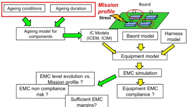
No tool exists to predict the EMC changes during the life cycle of a system. The purpose of this project is the development and the validation of a generic methodologic platform to characterize and model components EMC behavior taking in account ageing. The Figure 2 illustrates the targeted development flow using EMC simulation to achieve EMC compliance in the long term.
CI CI CI CI
Board
IC Models
(ICEM, ICIM) Baord model
Equipment model
EMC simulation
Equipment EMC compliance ?
Ageing conditions Ageing duration Mission
profile Stress
Ageing model for components
EMC level evolution vs. Mission profile ? EMC non compliance
risk ?
Sufficient EMC margins?
Harness model
Figure 2. Development flow using parameter adaptive model allowing equipment EMC compliance prediction
This flow requires the modeling of each parts of this equipment: electronic components (active and passive), tracks, power plans, harness, connectors... A vast literature exists on the modelling of these different parties and more or less established techniques are proposed. The use of electrical and/or electromagnetic simulators enables to calculate emission or immunity conducted or radiated by this equipment levels and check compliance towards an EMC specification.
The integration of the ageing parameter requires new information: the mission profile giving the stress conditions and stress typical duration. From these ageing conditions and an ageing model, it is possible to parameter IC EMC models as a function of time. Using these parameter adaptive models, it becomes possible to predict the evolution of EMC levels depending on the types and duration of stress. By integrating the statistical dispersion between components, it becomes also possible to calculate the probability of non-compliance EMC and therefore check whether EMC margins used to offset the impact of aging are sufficient or oversized.
However, the challenge is to establish these models of aging. The project aims to evolve the current components modeling standards proposing consideration of the effect of aging. The following models of IEC 62432 standard are targeted to be covered:
• ICEM-CE: Integrated Circuit Emission Model: Conducted Emission IEC 62432-2 [2]
• ICEM-RE: Integrated Circuit Emission Model: Radiated Emission IEC 62432-3 [3]
• ICIM-CI: Integrated Circuit Immunity Model: Conducted Immunity IEC 62432-4 [4]
A proposal of ICIM-RI: Integrated Circuit Immunity Model: Radiated Immunity and an application of the future standard ICFTM (Integrated Circuit Fast Transient Model) which could be considered as an extension of IBIS ( Input/output Buffer Information Specification) [5] model used for signal integrity are also concerned by our work.
III. DEMONSTRATORS
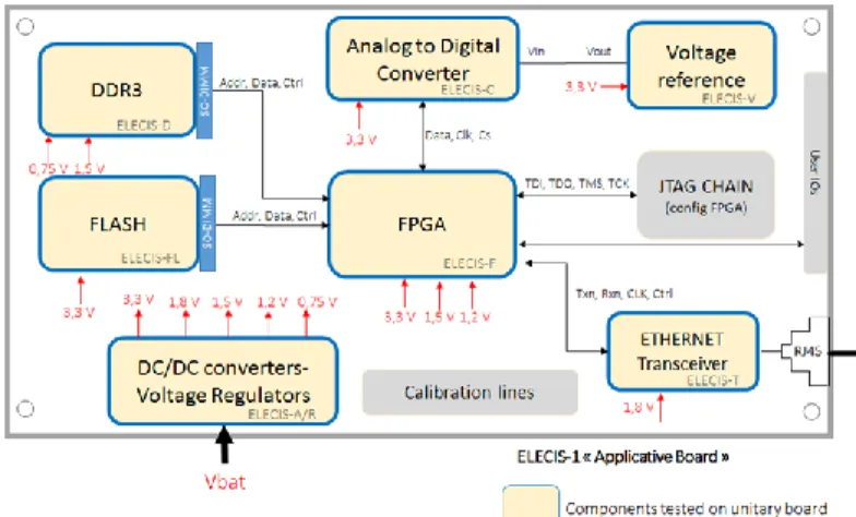
To demonstrate that these models allow prediction of the risk of non-compliance at the level of an electronic board, a set a demonstrators called ELECIS (Electronic board for Long term Electromagnetic Compatibility Issues Simulation) are build. An application demonstrator embed functions commonly used in aeronautical or automotive ECUs (Electronic Control Unit). As illustrated by figure 3, this application demonstrator has been designed around a FPGA addressing different types of memory (flash, MRAM, DDR3), communicating thru an external ETHERNET bus and supporting analogue functions as Analogue to Digital Converter (ADC), reference voltage and supplied by linear and switched power supplies.
Figure 3. ELECIS application demonstrator
Each function is realized by a component for which a unitary board is built to extract IC model. The table 1 gives the list of components which will be modelled. Transient Voltage Suppressor (TVS) as well as passive elements will be also modelled.
Table 1. List of targeted components
Board Component
ELECIS-F FPGA Xilinx Spartan 6 XC6SLX16-2FTG256I
ELECIS-FL FLASH Spansion S34ML01G2
ELECIS-D DDR3 Micron Technology MT41J256M16HA-125IT
ELECIS-M MRAM Everspin Technologies MR4A08BCYS35
ELECIS-T Ethernet Micrel KSZ9021RNI Transceiver
ELECIS-C AD Converter Analog Device AD7476
ELECIS-V Voltage Reference Linear Technology LTC1798
ELECIS-A DC/DC converter Linear Technology LT3800
ELECIS-R Voltage Regulator Texas Instruments TPS70348
ELECIS-TR Buffer Texas Instruments 74FCT162543CTPACT
The figure 4 illustrates which models will be built for each targeted component.
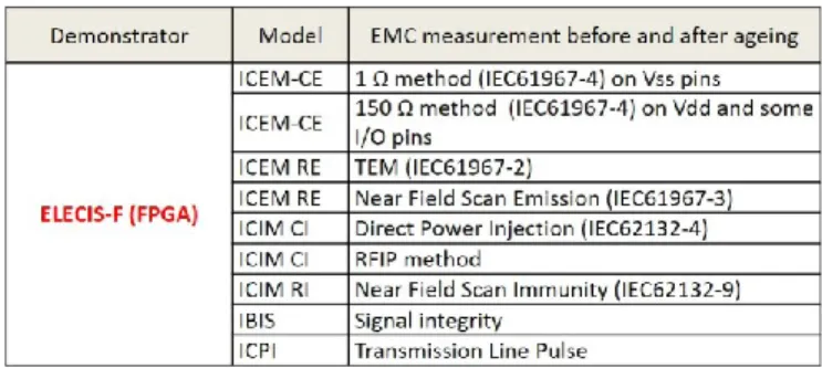
As example, the table 2 gives the list of EMC measurements which will be done on ELECIS-F board to obtain the corresponding IC-EMC model.
Table 2. List of EMC measurements to perform on ELECIS-F board to obtain the corresponding IC-EMC model
As illustrated by the figure 5, the Equipped Board Emission Model-CE (EBEM-CE) will be built as a “white box” from ICEM-CE model of each component associated to PCB tracks models and to passive components models.
Figure 5. ELECIS-1 Emission Model White box construction
The simulation of the conducted emission obtained through the EBEM-CE model will be compared to CISPR25-CE measurement before and after ageing. An example of EBEM-CE model construction with a comparison simulation vs measurement is given in [6].
As illustrated by the figure 6, the Equipped Board Immunity Model-CI (EBIM-CI) will be built as a “white box” from ICIM-CI model of each component associated to PCB tracks models and to passive components models.
Figure 6. ELECIS-1 Immunity Model White box construction
The simulation of the conducted emission obtained through the EBIM-CI model will be compared to BCI (Bulk Current Injection) ISO11452-4 [7] measurement before and after
ageing. An example of EBIM-CI model construction with a comparison simulation vs measurement is given in [8] and [9]. IV. FIRSTRESULTS
A part of the first results is presented in [10] which describes the methodology used to extract the PDN (Passive Distribution Network) and the IA (Internal Activity) of the ICEM-CE model in case of complex IC using multiple power voltages.
Another result is a multiport ICIM-CI modeling approach applied to a commercial bandgap voltage reference LTC1798-2.5V from Linear Technology. The PDN of the ICIM-CI model is extracted from full S-parameters measurements when the Immunity Behavior (IB) is obtained from multiple Direct Power Injection (DPI) [11] measurements realized on ELECIS-V board.
The aim of this study is to determine a mathematical equation describing the immunity behavior of the component when an interference signal is injected at its input and its output. In order to define this equation, several DPI measurements are performed for different frequencies to express VOUT as a function of the forward power on the VDD
pin and as function of the transmitted power on the VOUT pin.
We notice that Vout is linearly dependent on the forward power (Pforw) and could be expressed by equation (1) when the perturbance is applied on VDD pin where Cin(f) corresponds to the slop of the linear function and Vref to the bandgap reference voltage.
Vout = Vref + Cin (f)*PFORW_VDD (1)
The figure 7 presents Cin as a function of the frequency when Vref is fixed to 2.5 V. Cin(f) is similar to S11 parameter.
Figure 7. DPI set-up applied to LTC1798
The same is observed when the perturbance is applied to VOUT leading to equation (2)
Vout = Vref + Cout (f)*PFORW_VOUT (2)
Cout(f) is similar to S22 parameter.
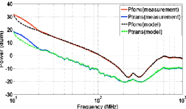
The model is finally used to determine the immunity curve when interference is injected at the output of the component for an immunity criterion of Vout ±5 mV. The Figure 8 shows the comparison of measured and calculated forward and transmitted powers. The model curves fit the measurement curves.
Figure 8. Comparison measured vs calculated forward and transmitted powers at DUT level
Another result comes from the study of ageing effects on the signal integrity of a commercial buffer 74FCT162543CTPACT from Texas Instruments. The following characteristics have been monitored: peak to peak magnitude at buffer output, rise and fall time at buffer output and static I(V) characteristics of the pull-up and pull-down output stage transistors. A static electrical stress has been applied on the power supply. When the nominal power voltage was 5V, stress applied varied between 7 V and 8,8 V. A statistical study has been performed on 8 parts. As illustrated by figure 9, the electrical stress leads to a reduction of eye diagram.
Figure 9. Effect of ageing on the signal integrity of a buffer
Even if these shifts are significant and above the measurement’s repeatability and component’s variability, the shift’s levels are low: 3.4 % of peak to peak magnitude, 5.3 % of the rise time and 3,5 % of the fall time.
Concerning the static characteristics, we observe a current’s decrease depending of output voltage. This decrease could reaches 5 mA for the pull-down as illustrated by figure 10 (-5,6% of the nominal current) and up to 3,5 mA for the pull-up (-8,8% of the nominal current).
Figure 10. Effect of ageing on I(V) characteristics of pull-down transistor
These values are low but significant and higher than measurement uncertainty and component’s variability. Ageing effect is not symmetrical: pull down transistor is more degraded than pull-up-one.
ACKNOWLEDGMENT
This study is a part of IRT Saint-Exupery’s Electronics Robustness project sponsored by Airbus Operations, Airbus Group Innovations, Continental Automotive France, Hirex Engineering, Labinal Power Systems, Nexio, Thales Alenia Space France, Thalès Avionics, and the French National Agency for Research (ANR)
REFERENCES
[1] CISPR25 2008-3: Radio disturbance characteristics for the protection of receivers used on board vehicles, boats and on devices: Limits and methods of measurement
[2] IEC 62432-2- Integrated Circuit - EMC IC modeling – Part 2: ICEM-CE: Integrated Circuit Emission Model: Conducted Emission
[3] IEC 62432-3 - Integrated Circuit - EMC IC modeling – Part 3: ICEM-RE: Integrated Circuit Emission Model: Radiated Emission
[4] IEC 62432-4 -Integrated Circuit - EMC IC modeling – Part 4: ICIM-CI, Integrated Circuit Immunity Model, Conducted Immunity
[5] IEC 62014-1 (2001-05) Electronic design automation libraries – Part 1: Input/output buffer information specifications (IBIS version 3.2)
[6] “Practical Implementation of Conducted EMI Noise Modeling of Switching Devices - Time and Frequency-domain approaches” A. Ramanujan, F. Lafon, P. Fernandez-Lopez, EMC Europe 2013, Brugge
[7] ISO 11452-4 (2005): Road vehicles – Component test methods for electrical disturbances from narrowband radiated electromagnetic energy – Part 4: Bulk current injection (BCI) [8] “Novel modeling strategy for a BCI set-up applied in an automotive application” Durier, A. ; Pues, H. ; Vande Ginste, D. ; Chernobryvko, M. ; Gazda, C. ; Rogier, H. EMC Compo 2011, Dubrovnik
[9] “Using the EM simulation tools to predict EMC immunity behavior of an automotive electronic board after a component change” Durier, A.; Marot, C. ; Alilou O.;, EMC Europe 2013, Brugge
[10] ”Construction of an Integrated Circuit Emission Model of a FPGA using ICEM-CE” C.Ghfiri, A.Boyer, A.Durier, S.Ben Dhia - APEMC 2016, Shenzhen
[11] IEC 62132-4 (2006): Integrated circuits – Measurement of electromagnetic immunity, 150 kHz to 1 GHz – Part 4: Direct RF power injection method