HAL Id: hal-03201680
https://hal.archives-ouvertes.fr/hal-03201680
Single-Crystalline Body Centered FeCo Nano-Octopods:
from One-Pot Chemical Growth to Complex 3D
Magnetic Configuration
Cyril Garnero, Alexandre Pierrot, Christophe Gatel, Cécile Marcelot, Raul
Arenal, Ileana Florea, Anne Bernand-Mantel, Katerina Soulantica, Patrick
Poveda, Bruno Chaudret, et al.
To cite this version:
Cyril Garnero, Alexandre Pierrot, Christophe Gatel, Cécile Marcelot, Raul Arenal, et al.. Single-Crystalline Body Centered FeCo Nano-Octopods: from One-Pot Chemical Growth to Complex 3D Magnetic Configuration. Nano Letters, American Chemical Society, inPress, �10.1021/acs.nanolett.1c01087�. �hal-03201680�
Single-Crystalline Body Centered FeCo
Nano-Octopods: from One-Pot Chemical Growth to
Complex 3D Magnetic Configuration
Cyril Garnero,1+ Alexandre Pierrot,1+ Christophe Gatel,2 Cécile Marcelot, 2 Raul Arenal,3,4,5
Ileana Florea,6 Anne Bernand-Mantel,1 Katerina Soulantica,1 Patrick Poveda,7 Bruno
Chaudret,1 Thomas Blon,1 Lise-Marie Lacroix,1*
1. Université de Toulouse, UMR 5215 INSA, CNRS, UPS, Laboratoire de Physique et Chimie des Nano-Objets, 135 avenue de Rangueil F-31077 Toulouse cedex 4, France 2. Centre d’Elaboration de Matériaux et d’Etudes Structurales, CEMES-CNRS, 29 rue
Jeanne Marvig, 31055 Toulouse, France 3. Fundacion ARAID, 50018 Zaragoza, Spain
4. Laboratorio de Microscopias Avanzadas (LMA), Universidad de Zaragoza, Calle Mariano Esquillor, 50018 Zaragoza, Spain
5. Instituto de Nanociencia y Materiales de Aragon (INMA), CSIC-U. de Zaragoza, Calle Pedro Cerbuna 12, 50009 Zaragoza, Spain
6. Laboratoire de Physique des Interfaces et des Couches Minces (LPICM), CNRS-Ecole Polytechnique, IP Paris, Route de Saclay, 91128 Palaiseau Cedex, France
7. ST Microelectronics Tours, 10 rue Thalès de Milet, CS 97155, 37071 Tours Cedex 2, France
KEYWORDS. Magnetic nanoparticles, Bimetallic alloy, High index facets, Electron holography, Micromagnetic simulations, Vortex, Anti-vortex
ABSTRACT. Single crystalline magnetic FeCo nanostars were prepared using an organometallic
approach under mild conditions. The fine tuning of the experimental conditions allowed the direct synthesis of these nano-octopods with body-centered cubic (bcc) structure through a one-pot reaction, contrarily to the seed-mediated growth classically used. The FeCo nanostars consist of 8 tetrahedrons exposing {311} facets, as revealed by high resolution transmission electron Microscope (HRTEM) imaging and electron tomography (ET), and exhibit a high magnetization comparable with the bulk one (Ms = 235 A.m².kg-1). Complex 3D spin configurations resulting
from the competition between dipolar and exchange interactions are revealed by electron holography. This spin structures are stabilized by the high aspect ratio tetrahedral branches of the nanostars, as confirmed by micromagnetic simulations. This illustrates how magnetic properties can be significantly tuned by nanoscale shape control.
INTRODUCTION.
Nanoparticles (NPs) exhibiting complex shape combining high surface area and reactive facets such as concave nanocubes, nano-octopods or nanostars have been highly investigated in the field of catalysis due to their enhanced performances as compared to their isotropic counterparts (cubes, spheres) and to nanoparticles present in commercial catalysts.1,2,3,4 Shape-controlled mono- (Pt,3
Pd,5 Rh,6 Au7) and bi-metallic (Pt3Co,4 PtNi,8 AuPd9) catalytically active nanoparticles have been
prepared by liquid phase chemistry. While isotropic NPs exhibiting low-energy {100}, {111} or {110} facets are commonly obtained, the stabilization of a negatively-curved concave structure exposing high-index facets requires a kinetic control of the reaction rather than a thermodynamic one.10,11 Therefore, different approaches have been used to promote kinetic reactions, among
which faster precursor addition,6 higher heating rate12 or improved reducing agent strength.13
Alternatively, overgrowth on preformed seeds14 or stabilization of specific crystallographic facets
through ligand coordination,3,15 have been also successfully developed.
The shape control, essential for catalytic applications, is also of particular interest for tuning magnetic properties. Indeed, the magnetic dipolar energy depends on the NP geometry and can induce a strong shape anisotropy for elongated particles. For most of the common 3d magnetic materials, such a shape anisotropy can be much larger than the magnetocrystaline one.16 In
(FePt24). Magnetic anisotropy was shown to be significantly enhanced in some studies, as
compared to the case of nanospheres and nanocubes commonly used,22 resulting in better
efficiency as MRI contrast agents12,20 and larger heating capacity for magnetic hyperthermia
applications.22
The exact magnetic configuration within such complex 3D objects has never been reported, although it could guide future rational design of optimized NPs. Previous reports have shown the potential interest of replacing oxides by materials exhibiting larger saturation magnetization values, such as metallic Fe, Co or their alloys.25,26 We have recently reported the synthesis of
single-crystalline FeCo NPs following an organometallic approach.27 Their size, shape and
chemical composition could be tuned by the experimental parameters (nature and concentration of ligands, precursor concentrations).27,28 As prepared, these NPs exhibited saturation magnetization
values comparable with the bulk one (Ms= 226 A.m².kg-1).27,29
In this paper, we report the synthesis and the advanced magnetic characterization of FeCo nano-octopods. These single-crystalline bcc nanostars are enclosed by high-energy {311} facets as revealed by advanced electron microscopy techniques. The mean size of the nanostars can be tuned from 12 to 90 nm by adjusting the reaction time. Local chemical analysis revealed a mean composition of Fe60Co40 very close to the permendur alloy, leading to high saturation
magnetization (235 A.m2.kg-1). Electron holography studies on single FeCo nanostars and the
corresponding micromagnetic simulations evidenced two magnetic states where the magnetization laid parallel to each of the 8 arms, while the center of the particle present either a relatively homogeneous magnetisation or a complex antivortex-like magnetic configuration. This
observation is in remarkable agreement with the low energy magnetisation configurations we obtained by micromagnetic simulations.
RESULTS AND DISCUSSION
FeCo NPs were obtained by the co-reduction of two organometallic precursors, {Fe[N(SiMe3)2]2}2 (Me = CH3) and {Co[N(SiMe3)2]2THF} (THF = tetrahydrofuran), at 150°C
under H2 atmosphere in presence of a mixture of palmitic acid (PA) and hexadecylamine (HDA)
ligands. The Fe65Co35 permendur alloy composition was targeted to reach the largest saturation
magnetization within the nanoparticles.28 Thus, the ratio of the introduced precursors was kept at
0.8 Co : 2 Fe in the whole study.
The shape of the final nanoparticles has been tuned by varying the acid (x) and amine (y) concentration used. (Equation 1, Figure S1).
0.8 + 2 + +
, °
⎯⎯⎯⎯⎯ (Eq. 1)
For low acid concentration ( ≤ 4), nanoparticles of small sizes and isotropic shapes (cubes and spheres) were obtained, due to a high nucleation rate. For ≥ 4.5, the partial stabilization of the precursor by palmitic acid leads to nanoparticles with octopod-like shape were observed concomitantly to small seeds (Figure S2). By optimizing the experimental conditions, we
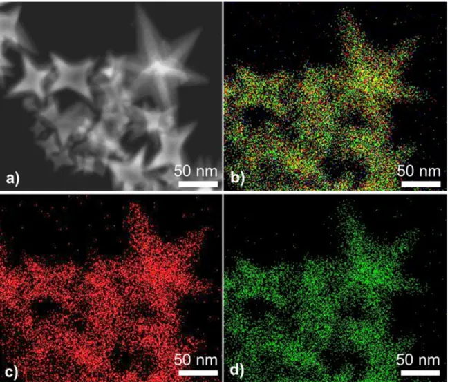
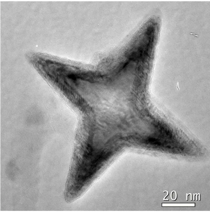
The 3D structure of the nanostars was statistically studied by scanning electron microscopy (SEM, Figure 1b). Most of the particles were oriented in order to expose four of their branches. These branches are symmetrically extending from the particle center and have a length of typically 40 nm. Few particles were tilted allowing observing six of their branches (Figure S3). Series of scanning transmission electron microscope (STEM) images using high-angle annular dark field detector (HAADF) have been acquired on an isolated FeCo nanostar. The reconstructed tomogram reveals an octopod-like shape (Figure 1c-e, video S1) and confirms the presence of 8 arms stemming out of the particle center. This agrees with the theoretical model of nanostars consisting of 8 identical tetrahedrons symmetrically distributed (Figure 1f-g, video S2), and used thereafter for micromagnetic simulations.
Figure 1. a) Transmission Electron Microscopy (TEM) and b) Scanning Electron Microscopy
(SEM) images of an assembly of FeCo nanostars. c-e) projections tilt series recorded in STEM-HAADF of an isolated single nanostar observed at different tilt angles c) -67°, d) + 31° and e)
confirmed that the nanostars consist of FeCo alloy, a mean composition of Fe57Co43 being
measured.
The expected bcc structure for all synthetized nanostars has been evidenced by powder X-ray diffraction (XRD) without additional parasitic crystalline phase (Figure S5). High-Resolution TEM images and electron diffraction patterns performed on several individual nanostars revealed their single-crystalline structure and confirmed the bcc crystalline phase. A thin oxide shell is observed at the nanostar surface. It is formed due to air exposure during the sample introduction, but does not impact the detailed analysis of the apex angle reported hereafter. Most of the nanostars observed stood on the TEM support on four of their branches and were thus viewed along the [001] zone axis of the FeCo bcc structure (Figures 2a-b and S6). Some nanostars layed on only two branches, revealing a [110] orientation (Figure S7) or even on a single branch, showing the expected six-fold symmetry diffraction pattern characteristic of the FeCo bcc structure observed along the [111] zone axis (Figures 3c-d). We performed a systematic and detailed analysis of the branches (length, angle) on the different projection views (Figure S8). Considering the symmetry of the nanostar, the projected edges and the mean apex angle of each arms observed along the different orientations, the nanostars were determined to exhibit high index {311} facets (Figure S9). Indeed, the experimental and theoretical apex angles are in very good agreement: 36 ± 1° vs 36.8° for [001] projections, 30 ± 1° vs 30.0° for [110] projections and 37 ± 1° vs 38.2° for [111] projections. for In the literature, a variety of high index facets have been determined on fcc-structure nanostars : {730},5 {310} and {420} in Pd,30 {411} in Pt,3 {722} in AuPd;13 while {311}
facets were reported for Fe3O420 and MnxFe1-xO.19 To the best of our knowledge, there is no other
Figure 2. a, c) HRTEM images and b, d) the corresponding selected area electron diffraction
(SAED) pattern of individual nanostars oriented along a-b) [001] and c-d) [111] zone axis. An oxide shell, formed due to air exposure during the sample introduction, is observed.
Growth mechanism study
To try to unravel the growth mechanism of these octopods, we studied the effect of the reaction time and temperature. Lowering the temperature down to 120°C did not affect the shape of the FeCo nanostars, but slightly broadens the size distribution (Figure S10). A kinetic study performed at 150°C revealed that even after short reaction times (6 h), small octopods were already formed (Figure S11). Extending the reaction time leads to the growth of the objects, the mean branch size increasing from 12 nm, after 6 h, to 60 nm after 7 days. One could notice that an overgrowth occurred for extended reaction time, leading to dendritic-like objects (Figure S11d). These objects exhibit a homogeneous chemical composition slightly enriched in Fe as compared to the nanostars obtained after 48 h of reaction (Figure S12, Fe57Co43 after 48h vs. Fe67Co33 after 7 days).
Nanostars, or octopods, are known to be kinetic objects, which could result either from the overgrowth of a seed or from the corrosion of a larger particle. In our case, FeCo nanostars most probably result from the overgrowth of cubic seeds along the [111] directions. Indeed, an octopod-like shape is observed even after short reaction time and on small size objects. The stabilization of the high-index facets seems to be promoted by the palmitic acid ligand. Indeed, a critical acid concentration of x = 4.5 allows favoring the octopod-like shape over the nanosphere and nanocube ones, though thermodynamically more stable. Such a drastic shape control was previously reported using the same iron precursor on pure Fe NPs.31 The stabilization of iron(II)carboxylate complexes
induced by the in-situ reaction of palmitic acid with iron precursor was determinant in the fine shape control observed. In the case of FeCo nanoparticles, the presence of two precursors leads probably to a far more complex mechanism, but the Fe-enrichment of the nanostar composition observed with time strengthened the hypothesis of the key effect of the acid and the resulting iron(II)carboxylate.
Investigation of magnetic properties
The magnetic properties of the nanostars obtained after 48h were measured in powder state using vibrational sample magnetometry (Figure S13). The nanostars exhibit a ferromagnetic behavior at 300 K, with a coercive field of 35 mT, a remanent magnetization MR and a saturation magnetization
MS, 3T of 20 ± 2 and 217 ± 5 A.m².kg-1, respectively. Once cooled down to 5 K under an applied
field of µ0H = 3T, a coercive field of 50 mT has been determined, while the hysteresis cycle did
not show any exchange-bias. The saturation magnetization raised up to MS, 3T = 235 ± 5 A.m².kg
-1, close to the bulk value (240 A.m².kg-1).32 The saturation field, was fairly large and did not
significantly evolve with the temperature (µ0HS = 780 mT, determined for M = 0.95 MS, 3T).
The magnetic configuration within individual nanostars was further studied experimentally by electron holography following a method we developed for investigating the magnetic properties of Fe nanocubes.33,34 To obtain representative results, the observations were reproduced on several
nanostars viewed along [001] or [111] orientation. In this respect, it is important to note that prior to electron holography, the nanostars were examined in conventional TEM to select some of them suitable for electron holography. Interestingly, all of the [001] oriented nanostars exhibit nearly no magnetic contrast (Figures 3a,c and S14a,c). On the contrary, the nanostars viewed along the [111] directions exhibit a very intriguing magnetic phase map (Figure 3b,d and S14b,d), resulting in a fairly localized magnetic induction (Figure 3e and S14e).
Figure 3. a-b) Conventional TEM images and c-d) the corresponding magnetic phase shift maps
determined by electron holography for individual nanostars oriented along a,c) [001] and b,d,e) [111] zone axis. e) Vectorial magnetic map with flux lines calculated from the experimental phase shown in d), corresponding to the magnetic induction flux lines around the [111] nanostar. The inset color wheel indicates the direction of the magnetic induction. Scale bar = 20 nm.
To understand this discrepancy between the [001] and [111]-oriented nanostars, micromagnetic simulations were performed, considering the size of the star observed and the specific magnetic history. Once deposited on a grid, the nanostars were initially exposed to a 1 T magnetic field during the TEM pre-observation. This field, due to the objective lens of the microscope, is perpendicular to the grid and thus applied along the [001] or [111] directions, depending on the relative nanostar orientation. Such a parasitic magnetic field being absent in the holography dedicated microscope in Lorentz mode, the magnetic configurations observed correspond to the remanent state (µ0H = 0).
Two different magnetic spin structures were determined by micromagnetic simulations. The first configuration, shown in Figure 4, corresponds to the remanent magnetic state with the minimum of energy, i.e. the ground state, and was observed after application of the 1 T saturating field along the [001] direction of the nanostar (video S3). In this configuration, the saturation field direction and the electron path correspond to the z axis, and the image plane to the (xy) plane. The magnetization is homogeneous in the center of the star, while pointing in or out along the branches (see Figure 4a-b). We will refer to this configuration as the “flower state” as it presents strong
Figure 4. a) 3D view of the magnetization in the “flower” state obtained at remanence after
application of a saturating field of 1T in the [001] direction (z axis). b) Schematic view of a), the arrows indicate the moment orientation and the partial curling of the spin. Cross-sections perpendicular to the z axis of the magnetic spins at c) the top, d) the middle and e) at the bottom of the nanostar core.
In the case of FeCo nanocubes, this relatively homogeneous configuration is observed only for cubes slightly smaller than the vortex limit, i.e. for ~ 20 nm cubes.36 This magnetic transition as
a function of the size is explained by the competition between the dipolar energy and the exchange energy.34 The stabilization of the flower state in the present FeCo nanostar is thus remarkable,
since it presents much larger dimensions than the 20 nm nanocube. Its core can contain a 30 nm sided cube. This particularity illustrates the dominant role played by shape anisotropy: the magnetization is forced to align along the arms’ direction due to their high aspect ratio, thus stabilizing the flower state in a relatively large nano-object. Another particularity is distinguishing this nanostar flower state from the classical flower state in cubes.34 Upon closer observation of the
two sides of the nanostar perpendicular to the core magnetization direction [001] (i.e. (001) planes, see Figure 4c-e), we observe a curling pattern which resembles to the vortex state of a cube. It means that the homogeneous magnetization in the center of the cube, characteristic of the flower state, is terminated at each (001) extremity by a curling of moments. This curling, enabled by the relatively large dimensions of the nanostar, allows reducing the dipolar energy. It presents however an important difference with the classical vortex configuration in cubes. While the cube vortex configuration possesses a unique helicity (as defined by Schabes et al.35), which is equal at the two
cube faces, we observe a helicity reversal for both sides of the nanostar (compare Figures 4c and 4e). Moreover, the vorticity is cancelled in the central plane where the magnetization direction is mainly homogeneous and pointing toward the [001] direction as can be seen in Figure 4a,d. Such
the 3D flower state presents a reversal of the (x-y) magnetic components for symmetric branches while the z component keeps the same direction parallel to the initial magnetic field. Thus, all magnetic in-plane components of each x-y plane have their symmetric reversed counterpart. As a consequence, the integration of these in-plane components along the z axis (parallel to the electron beam) results in no or little contrast in electron holography (Figure S15), in agreement with the experimental observations (Figure 3c).
A second magnetic spin structure at the remanent state was determined by micromagnetic simulations on nanostars observed along the [111] zone axis. (Figure 5, video S4) A nanostar of 90 nm, initially exposed to a 1 T saturation field in the [111] direction, i.e. along one branch, was allowed to relax in the absence of external field. The z axis and the (x-y) planes (parallel to the image plane) of the simulation corresponds here to the [111] direction and (111) planes, respectively. The resulting induction flux lines (Figure 5b) and magnetic phase shift map (Figure 5d) were simulated. A very good agreement between simulations and experimental observations was obtained, as shown by the quantitative comparison between experimental and simulated phase shift profiles (Figure 5e). The remanent state corresponds then to a configuration in which the spins lay parallel all along the [111] diagonal, even in the nanostar core (Figure 5f, white arrow).
Figure 5. a) Experimental and b) simulated magnetic flux lines superimposed with conventional
TEM image contrast and simulated nanostar projected along the [111] direction, respectively. c) Experimental and d) simulated phase shift maps. Scale bar = 20 nm e) Measured and simulated phase shift profiles obtained along the dashed arrows in c) and d). f) Schematic view of the magnetic configuration g). The white arrow evidence the [111] diagonal along which the 1T field was initially applied prior to relaxation. h) Magnetization in the (111) plane at the center of the nanostar.
The magnetization in the (111) plane perpendicular to the [111] direction at the center of the nanostar reveals an intriguing spin structure, as shown in Figure 5h, where the cross-section, taking the form of a hexagon, is shown. In this 2D cross-section, the magnetization in each side of the hexagon is imposed by one of the star’s branche, which are alternatively pointing in or out leading to a total 4π rotation of moments in the plane. Consequently, the projection of the magnetic configuration in this (111) plane resembles to a 4π antivortex (Figure S16). However, one should keep in mind that the real spin configuration is 3D and thus much more complex than a 2D projection.
CONCLUSION
We report here on the synthesis of FeCo nano-octopods using an organometallic approach. By adjusting the experimental conditions, a kinetic reaction control was reached. Single-crystalline
bcc-nanostars exhibiting high index {311} facets were prepared. While they exhibit a saturation
magnetization close to the bulk one, their magnetic configuration is strongly affected by their peculiar 3D shape. The presence of the eight branches induces a strong shape anisotropy and results in complex flower-like or anti-vortex like configuration in the nanostar center. If the critical impact of the nano-octopod shape on the catalytic activity has been already well-established in the literature, this study clearly reveals the impact of this geometry on the magnetic properties, for instance by stabilizing a flower state on relatively large nano-objects. In the framework of magnetically-activated catalysis, such nanostars, obtained from a single-pot reaction, open promising perspectives to combine in a single object heating efficiency and highly reactive catalysts.
ASSOCIATED CONTENT
Supporting Information. Experimental section: FeCo nanostars synthesis, characterization
[111] (Video S4) oriented nanostars. Schematic view of the 4π antivortex-like structure observed at the nanostar center.
AUTHOR INFORMATION
Corresponding Author
* Lise-Marie Lacroix, lmlacroi@insa-toulouse.fr, Tel: +33567048833, Fax: +33561559697.
Author Contributions
The manuscript was written through contributions of all authors. + C. Garnero and A. Pierrot
contributed equally to the results reported. C. Garnero performed the octopod synthesis. A. Pierrot, A. Bernand-Mantel and T. Blon performed the micromagnetic simulations. C. Garcia-Marcelot conducted STEM-EDX characterization, R. Arenal performed the electron tomography experiments and I. Florea the corresponding 3D reconstruction. C. Gatel conducted the electron tomography experiment. K. Soulantica, B. Chaudret, P. Poveda, T. Blon, C. Gatel and LML were in charge of the experiments.
Funding Sources
This work was performed in the frame of TOURS 2015, project supported by the French « Programme de l’économie numérique des Investissements d’Avenir». This work was also supported by the Agence Nationale de la Recherche (France) under contract No. ANR-14-CE07-0025-01 (DENSAR). Some of this research has been also supported by the Spanish MICINN
(PID2019-104739GB-100/AEI/10.13039/501100011033) and European Union H2020 program “ESTEEM3" (823717).
ACKNOWLEDGMENT
This work was performed in the frame of TOURS 2015, project supported by the French « Programme de l’économie numérique des Investissements d’Avenir». T. Blon and A. Pierrot thank the Agence Nationale de la Recherche (France) for financial support (contract No. ANR-14-CE07-0025-01 DENSAR. We gratefully acknowledge the International Associated Laboratory (LIA)-M²OZART for financial support. Some of the HRSTEM and EELS studies were conducted at the Laboratorio de Microscopias Avanzadas, Universidad de Zaragoza, Spain. R. A. gratefully acknowledges the support from the Spanish MICINN (PID2019-104739GB-100/AEI/10.13039/501100011033) and European Union H2020 program “ESTEEM3" (823717). REFERENCES
(1) Quan, Z.; Wang, Y.; Fang, J. Igh-Index Faceted Noble Metal Nanocrystals. Acc. Chem. Res.
46 (2), 191–202. https://doi.org/10.1021/ar200293n.
(2) Zhang, H.; Jin, M.; Xia, Y. Noble-Metal Nanocrystals with Concave Surfaces: Synthesis and Applications. Angew. Chem. Int. Ed. 2012, 51 (31), 7656–7673.
https://doi.org/10.1002/anie.201201557.
(3) Huang, X.; Zhao, Z.; Fan, J.; Tan, Y.; Zheng, N. Amine-Assisted Synthesis of Concave Polyhedral Platinum Nanocrystals Having {411} High-Index Facets. J. Am. Chem. Soc. 2011,
(6) Zhang, H.; Li, W.; Jin, M.; Zeng, J.; Yu, T.; Yang, D.; Xia, Y. Controlling the Morphology of Rhodium Nanocrystals by Manipulating the Growth Kinetics with a Syringe Pump. Nano
Lett. 2011, 11 (2), 898–903. https://doi.org/10.1021/nl104347j.
(7) Zhang, J.; Langille, M. R.; Personick, M. L.; Zhang, K.; Li, S.; Mirkin, C. A. Concave Cubic Gold Nanocrystals with High-Index Facets. J. Am. Chem. Soc. 2010, 132, 14012–14014. https://doi.org/10.1021/ja106394k.
(8) Wu, Y.; Wang, D.; Niu, Z.; Chen, P.; Zhou, G.; Li, Y. A Strategy for Designing a Concave Pt-Ni Alloy through Controllable Chemical Etching. Angew. Chem. Int. Ed. 2012, 51 (50), 12524–12528. https://doi.org/10.1002/anie.201207491.
(9) Weiner, R. G.; DeSantis, C. J.; Cardoso, M. B. T.; Skrabalak, S. E. Diffusion and Seed Shape: Intertwined Parameters in the Synthesis of Branched Metal Nanostructures. ACS Nano 2014,
8 (8), 8625–8635. https://doi.org/10.1021/nn5034345.
(10) Watt, J.; Cheong, S.; Tilley, R. D. How to Control the Shape of Metal Nanostructures in Organic Solution Phase Synthesis for Plasmonics and Catalysis. Nano Today 2013, 8 (2), 198–215. https://doi.org/10.1016/j.nantod.2013.03.001.
(11) Wang, Y.; He, J.; Liu, C.; Chong, W. H.; Chen, H. Thermodynamics versus Kinetics in Nanosynthesis. Angew. Chem. Int. Ed. 2015, 54, 2022–2051.
https://doi.org/0.1002/anie.201402986.
(12) Douglas, F. J.; MacLaren, D. A.; Tuna, F.; Holmes, W. M.; Berry, C. C.; Murrie, M. Formation of Octapod MnO Nanoparticles with Enhanced Magnetic Properties through Kinetically-Controlled Thermal Decomposition of Polynuclear Manganese Complexes.
Nanoscale 2014, 6 (1), 172–176. https://doi.org/10.1039/C3NR04832B.
(13) Wang, L.-B.; Wang, Y.-C.; Guo, H.-Y.; Huang, J.-L.; Zhao, Y.-L.; Liu, Q.-Y.; Wu, X.; Zeng, J. Au–Pd Alloy Octapods with High Electrocatalytic Activity for the Oxidation of Formic Acid. Part. Part. Syst. Charact. 2015, 32, 295–300. https://doi.org/10.1002/ppsc.201400130. (14) Lee, S. R.; Park, J.; Gilroy, K. D.; Yang, X.; Figueroa-Cosme, L.; Ding, Y.; Xia, Y. Palladium@Platinum Concave Nanocubes with Enhanced Catalytic Activity toward Oxygen Reduction. Chem Cat Chem 2016, 8, 3082–3088. https://doi.org/10.1002/cctc.201600600. (15) Collins, G.; Schmidt, M.; McGlacken, G. P.; O’Dwyer, C.; Holmes, J., D. Stability,
Oxidation, and Shape Evolution of PVP-Capped Pd Nanocrystals. J Phys Chem C 2014, 118, 6522–6530.
(16) Vereda, F.; de Vicente, J.; Hidalgo-Álvarez, R. Physical Properties of Elongated Magnetic Particles: Magnetization and Friction Coefficient Anisotropies. ChemPhysChem 2009, 10 (8), 1165–1179. https://doi.org/10.1002/cphc.200900091.
(17) Kodama, R. H.; Berkowitz, A. E. Atomic-Scale Magnetic Modeling of Oxide Nanoparticles.
Phys Rev B 1999, 59 (9), 6321.
(18) Kihal, A.; Fillion, G.; Bouzabata, B.; Barbara, B. High Field Surface Magnetic Study of Fe3O4 Nanoparticles. Phys Status Solidi B 2012, 249 (3), 604.
(19) Lee, P.-Y.; Teng, H.-S.; Yeh, C.-S. Preparation of Superparamagnetic MnxFe1−xO Nanoparticles from Low-Index-Facet Cubes to High-Index-Facet Concave Structures and Their Catalytic Performance in Aqueous Solution. Nanoscale 2013, 5 (16), 7558. https://doi.org/10.1039/c3nr01865b.
(20) Zhao, Z.; Zhou, Z.; Bao, J.; Wang, Z.; Hu, J.; Chi, X.; Ni, K.; Wang, R.; Chen, X.; Chen, Z.; Gao, J. Octapod Iron Oxide Nanoparticles as Highperformance T2 Contrast Agents for Magnetic Resonance Imaging. Nat. Commun. 2013, 4, 2266.
(21) Situ-Loewenstein, S. F.; Wickramasinghe, S.; Abenojar, E. C.; Erokwu, B. O.; Flask, C. A.; Lee, Z.; Samia, A. C. S. A Novel Synthetic Route for High-Index Faceted Iron Oxide Concave Nanocubes with High T2 Relaxivity for in Vivo MRI Applications. J. Mater. Sci.
Mater. Med. 2018, 29, 58.
(22) Nemati, Z.; Alonso, J.; Martinez, L. M.; Khurshid, H.; Garaio, E.; Garcia, J. A.; Phan, M. H.; Srikanth, H. Enhanced Magnetic Hyperthermia in Iron Oxide Nano-Octopods: Size and Anisotropy Effects. J. Phys. Chem. C 2016, 120, 8370–8379.
https://doi.org/10.1021/acs.jpcc.6b01426.
(23) Khurshid, H.; Chandra, S.; Li, W.; Phan, M. H.; Hadjipanayis, G. C.; Mukherjee, P.; Srikanth, H. Synthesis and Magnetic Properties of Core/Shell FeO/Fe3O4 Nano-Octopods. J. Appl.
Phys. 2013, 113, 17B508. https://doi.org/10.1063/1.4794978.
(24) Chou, S.-W.; Zhu, C.-L.; Neeleshwar, S.; Chen, C.-L.; Chen, Y.-Y.; Chen, C.-C. Controlled Growth and Magnetic Property of FePt Nanostructure: Cuboctahedron, Octapod, Truncated Cube, and Cube. Chem. Mater. 2009, 21 (20), 4955–4961.
https://doi.org/10.1021/cm902199p.
(25) Carrey, J.; Mehdaoui, B.; Respaud, M. Simple Models for Dynamic Hysteresis Loop Calculations of Magnetic Single-Domain Nanoparticles: Application to Magnetic Hyperthermia Optimization. J. Appl. Phys. 2011, 109 (8), 083921.
https://doi.org/10.1063/1.3551582.
(26) Wu, L.; Mendoza-Garcia, A.; Li, Q.; Sun, S. Organic Phase Syntheses of Magnetic Nanoparticles and Their Applications. Chem. Rev. 2016, 116 (18), 10473–10512. https://doi.org/10.1021/acs.chemrev.5b00687.
(27) Garnero, C.; Lepesant, M.; Garcia-Marcelot, C.; Shin, Y.; Meny, C.; Farger, P.; Warot-Fonrose, B.; Arenal, R.; Viau, G.; Soulantica, K.; Fau, P.; Poveda, P.; Lacroix, L.-M.; Chaudret, B. Chemical Ordering in Bimetallic FeCo Nanoparticles: From a Direct Chemical Synthesis to Application As Efficient High-Frequency Magnetic Material. Nano Lett. 2019,
19 (2), 1379–1386. https://doi.org/10.1021/acs.nanolett.8b05083.
(28) Marbaix, J.; Mille, N.; Lacroix, L.-M.; Asensio, J. M.; Fazzini, P.-F.; Soulantica, K.; Carrey, J.; Chaudret, B. Tuning the Composition of FeCo Nanoparticle Heating Agents for Magnetically Induced Catalysis. ACS Appl. Nano Mater. 2020, 3 (4), 3767–3778. https://doi.org/10.1021/acsanm.0c00444.
(29) Lepesant, M.; Bardet, B.; Lacroix, L.-M.; Fau, P.; Garnero, C.; Chaudret, B.; Soulantica, K.; Defforge, T.; Valente, D.; Andreazza, C.; Billoué, J.; Poveda, P.; Gautier, G. Impregnation of High-Magnetization FeCo Nanoparticles in Mesoporous Silicon: An Experimental Approach. Front. Chem. 2018, 6. https://doi.org/10.3389/fchem.2018.00609.
(30) Jin, M.; Zhang, H.; Xie, Z.; Xia, Y. Palladium Concave Nanocubes with High-Index Facets and Their Enhanced Catalytic Properties. Angew. Chem. Int. Ed. 2011, 50, 7850–7854. https://doi.org/10.1002/anie.201103002.
(34) Gatel, C.; Bonilla, F. J.; Meffre, A.; Snoeck, E.; Warot-Fonrose, B.; Chaudret, B.; Lacroix, L.-M.; Blon, T. Size-Specific Spin Configurations in Single Iron Nanomagnet: From Flower to Exotic Vortices. Nano Lett. 2015, 15 (10), 6952–6957.
https://doi.org/10.1021/acs.nanolett.5b02892.
(35) Schabes, M. E.; Bertram, H. N. Magnetization Processes in Ferromagnetic Cubes. J. Appl.
Phys. 1988, 64 (3), 1347–1357. https://doi.org/10.1063/1.341858.
(36) Bonilla, F. J.; Lacroix, L.-M.; Blon, T. Magnetic Ground States in Nanocuboids of Cubic Magnetocrystalline Anisotropy. J. Magn. Magn. Mater. 2017, 428, 394–400. https://doi.org/10.1016/j.jmmm.2016.12.069.
(37) Ivanov, Y. P.; Chuvilin, A.; Vivas, L. G.; Kosel, J.; Chubykalo-Fesenko, O.; Vázquez, M. Single Crystalline Cylindrical Nanowires – toward Dense 3D Arrays of Magnetic Vortices.
Supporting information
Single-Crystalline Body Centered FeCo
Nano-Octopods: from One-Pot Chemical Growth to
Complex 3D Magnetic Configuration
Cyril Garnero,1 Alexandre Pierrot,1 Christophe Gatel,2 Cécile Marcelot, 2 Raul Arenal,3,4,5
Ileana Florea,6 Anne Bernand-Mantel,1 Katerina Soulantica,1 Patrick Poveda,7 Bruno
Chaudret,1 Thomas Blon,1 Lise-Marie Lacroix,1
1. Université de Toulouse, UMR 5215 INSA, CNRS, UPS, Laboratoire de Physique et Chimie des Nano-Objets, 135 avenue de Rangueil F-31077 Toulouse cedex 4, France 2. Centre d’Elaboration de Matériaux et d’Etudes Structurales, CEMES-CNRS, 29 rue
Jeanne Marvig, 31055 Toulouse, France 3. Fundacion ARAID, 50018 Zaragoza, Spain
4. Laboratorio de Microscopias Avanzadas (LMA), Universidad de Zaragoza, Calle Mariano Esquillor, 50018 Zaragoza, Spain
5. Instituto de Nanociencia y Materiales de Aragon (INMA), CSIC-U. de Zaragoza, Calle Pedro Cerbuna 12, 50009 Zaragoza, Spain
6. Laboratoire de Physique des Interfaces et des Couches Minces (LPICM), CNRS-Ecole Polytechnique, IP Paris, Route de Saclay, 91128 Palaiseau Cedex, France
7. ST Microelectronics Tours, 10 rue Thalès de Milet, CS 97155, 37071 Tours Cedex 2, France
Table of content : Experimental section
Synthesis of FeCo nanostars 3
Characterization 3
Micromagnetic simulations 4
Figure S1: TEM images of FeCo NPs obtained with low PA concentration 5 Figure S2: TEM image and corresponding size distribution of FeCo nanostars 6
Figure S3. SEM images of FeCo nanostars. 6
Figure S4. STEM-EDX mapping on FeCo nanostars obtained after 48h of reaction. 7 Figure S5. X-Ray diffraction (XRD) pattern of FeCo nanostars obtained after 48h of reaction. 8 Figure S6. HRTEM image of individual nanostar oriented along <001> zone axis. 9 Figure S7. HRTEM image of an individual nanostar oriented along <011> zone axis. 10 Figure S8. HRTEM images of branches of a) [011] and b) [111]-oriented nanostars. 11
Figure S9. HRTEM image of [001]-oriented nanostar 12
Figure S10. TEM image and size distribution of nanostar prepared at 120°C 13 Figure S11. TEM images of nanostars obtained after different reaction time 14 Figure S12. STEM-EDX mapping on FeCo nanostars obtained after 7 days of reaction. 15 Figure S13. 300K and 5K hysteresis cycles measured on powder samples 15 Figure S14. Additional electron holography images of a [001] and [111]-oriented nanostar 16 Figure S15. Simulated magnetic phase shift for a [001]-oriented nanostar 17 Figure S16. Schematized view evidencing the 4π antivortex-like structure. 18
Video S1. Projection tilt series recorded in STEM-HAADF of an isolated single nanostar Video S2. Three-dimensional reconstruction of the nanostar obtained by electron tomography Video S3. Magnetic spin structure observed at remanence in [001] oriented nanostar
EXPERIMENTAL SECTION
Synthesis of FeCo nanostars.
All solvents were purified on alumina desiccant (Pure Solv, Innovativ Technology) and degassed by bubbling Ar into the solvent for 10 min to remove any oxygen traces. Typically, in a glove box, 82.8 mg (0.22 mmol) of Fe(N(Si(CH3)3)2)2 (>99.9%, Nanomeps) and 39.9 mg (0.088 mmol) of
Co(N(Si(CH3)3)2)2,THF (>99.9%, Nanomeps) were separately dissolved in 0.5 ml of mesitylene
(99%, Merck) and then mixed, leading to a dark green solution. 170.3 mg of palmitic acid (PA, 0.66 mmol, Sigma, 99%) and 79.9 mg of hexadecylamine (HDA, 0.33 mmol, Sigma, 99%) were dissolved in 2.5 ml and 1.5 ml of mesitylene respectively. The PA solution was added onto the precursor mixture, which became violet. The resulting solution was magnetically stirred during 5 min. The HDA solution was added, the solution remaining violet. The solution was transferred into a Fisher Porter bottle, pressurized at 3 bars of H2 and then heated 48 h at 150°C. Once cooled
down, the supernatant exhibited a dark blue color, revealing that the reduction of the precursors was not yet over after the 48 h of reaction. TEM characterization did not reveal any nanoparticle in the supernatant. All the particles were attached to the magnetic stirrer. The particles were washed three times with toluene (99%, Acros) to remove unreacted species and ligand excess. The particles were dried and kept as a powder (~50 mg) in the glove box. The ligands ratio, the reaction time and the temperature were varied to study their impact on the final size of the nanostars.
Characterizations
XRD measurements were performed on a PANalytical Empyrean diffractometer using Co-Kα radiation. In a glovebox, few mg of the powder was sealed between two kapton sheets to prevent any air exposure. Thermogravimetric Analysis (TGA) was performed on a Mettler-Toledo balance in air and under H2/Ar atmosphere to determine the metallic content of the final powder.
Magnetic measurements were performed using a Quantum Design Physical Property Measurement System (PPMS) in the Vibrating Sample Magnetometer (VSM) configuration. 10 mg of powder were introduced in a Teflon cap. 3T magnetization cycles were recorded at 300K and 5K after a 3T field cooling.
Electron microscopy sample were prepared by drop casting a toluene suspension of nanostars on carbon coated copper grids. The particles were redispersed using sonication in presence of a slight amount of HDA. The morphology was routinely assessed by Scanning Electron Microscopy (SEM) using a JEOL JSM 6700F and by Transmission Electron Microscopy (TEM) using a 100kV JEOL JEM 1011F. The mean length (Lm) and angles distribution were measured from the image
analysis on c.a. 50 nanostars using the ImageJ software (image magnification 250k).1
Energy X-ray dispersive analyses were conducted on a JEOL 2100F equipped with a SSD Brucker detector to determine at the nanostar scale the relative FeCo content.
STEM-It is worth noting that no evidence of irradiation damage in the samples was detected during the tilt series acquisition.
The Electron Holography experiments were carried out on a HF3300C (I2TEM) microscope of Hitachi High Technology (HHT). This electron microscope at 300 kV was designed for in situ TEM and electron holography studies in Lorentz mode. It is fitted with a cold field emission gun to achieve a high sensitivity to the phase shift, a dedicated CS corrector for large field of view
(Bcorr from CEOS company) and a dedicated stage to introduce the sample in a field free position above the objective lens. This optimized Lorentz mode increases the spatial resolution up to 0.5 nm, giving 1 nm accuracy for the nanoparticle size measurement. A double biprism configuration8
has been set to avoid Fresnel fringes and tune independently the interference area and the fringe spacing. Holograms with 0.5 nm of interfringe have been acquired after a 2 s exposure time. 5 holograms with 0.5 nm of interfringe have been recorded for each nanostar with an exposure time of 2 s per image (total exposure time: 10 s). From the 5 holograms acquired on a same nanostar, 5 phase images have been extracted with 1 nm of spatial resolution using homemade software and summed after correcting spatial drift. Magnetic contribution of the phase shift has been isolated by evaluating half of the difference of the two phase images obtained before and after removing and inverting the sample.
Micromagnetic simulations
Micromagnetic simulations were carried out using the 3D version of the micromagnetic code OOMMF-3D package.9 All simulations presented here were done by considering the size of the
measured nanostar presented in Fig. 3. The used magnetic parameters correspond to the ones of FeCo at room temperature: saturation magnetization = 1.95 MA/m, exchange stiffness = 17 pJ/m and cubic anisotropy constant = 0 kJ/m3 as expected from the measured composition and
bulk behavior.10 The conjugate-gradient approach has been used form calculations that were
stopped at convergence ( ⃗ × ⃗ × ⃗ < 0.02 A/m). For the meshing, a cubic cell of (1×1×1) nm3
was used and the total simulated space was (200×200×200) nm3. Note that the use of cubic cells
introduced deviations from the planar facets of the synthesized nanostars. In order to identify the ground state among the different metastable solutions that could be obtained, calculations were performed (i) relaxing the magnetization under applied zero magnetic field from a random orientation of the magnetic moments as the initial state, (ii) relaxing under applied zero magnetic field after application of a saturating field of 1T in the <001>, <110> and <111> directions, and comparing the total energy of the different obtained magnetic configurations.
0.8 2 6 !⎯⎯⎯⎯⎯#, ° $ % (Eq. 1)
Figure S1. Transmission Electron Microscopy (TEM) of FeCo nanoparticles obtained in presence
Figure S2. TEM image and the corresponding mean size distribution of FeCo nanoparticles
obtained in presence of 4.5 PA and 6 HDA after 48h at 150°C.
Figure S3. SEM images with a) low and b) high magnification of FeCo nanostars obtained in
Figure S4. STEM-EDX mapping of b) Fe, Co; c) Fe and d) Co elements within the FeCo nanostars
40 60 80 100 (110) (211) (200) In te n s it y ( A rb .U n it ) 2θ (°), Kα (Co)
Figure S5. X-Ray diffraction (XRD) pattern of FeCo nanostars obtained after 48h of reaction.
Figure S8. HRTEM images of branches of a) [011] and b) [111] oriented nanostars. The black
lines are guide to the eyes for the metallic core to be considered for the angle measurement. The dashed lines materialized the extrapolated apex angle.
Figure S9. HRTEM image of nanostar viewed along the [001] zone axis and the corresponding
FFT. The gray lines are guide to the eyes for the metallic core to be considered for the angle measurement.
Figure S10. TEM images and the corresponding mean size distribution of FeCo nanoparticles
Figure S11. TEM images of the nanoparticles obtained after a) 6h, b) 24h, c) 48h and d) 7 days of
Figure S12. STEM-EDX mapping of b) Fe, Co; c) Fe and d) Co elements within the FeCo
nanostars obtained after 7 days of reaction and revealing a chemical composition of Fe67Co33.
Figure S14. a) and b) Amplitude images of FeCo nanostrats observed along the [001] and [111]
zone axis respectively. c) and d) Corresponding magnetic phase shift maps. We can clearly see a very slight integrated magnetic induction showing the compensation of the magnetic phase shift along the electron path. The residual contrast on c) is due to a slight misalignment of the cube axis with the electron beam, or artifacts coming from diffraction contrasts and image alignment during the data treatment. e) Vectorial magnetic map with magnetic flux lines calculated from the experimental image shown in d). The color represents the direction of the magnetic induction following (color wheel in insert). Scale bar = 20 nm.
Figure S16. a) Magnetization in the (111) plane at the center of the nanostar determined by
micromagnetic simulations and b) the corresponding schematized view evidencing the 4π
antivortex-like structure. Color bar : ratio between the z component of the magnetization Mzand
the total magnetization MS.
References :
(1) Rasband, W. S. ImageJ Software. U. S. National Institutes of Health, Bethesda, Maryland, USA, http://rsb.info.nih.gov/ij/, 1997-2007.
(2) Saxton, W. O.; Baumeister, W.; Hahn, M. Three-Dimensional Reconstruction of Imperfect Two-Dimensional Crystals. Ultramicroscopy 1984, 13 (1–2), 57–70.
(3) Moldovan, S.; Arenal, R.; Ersen, O. 3D Nanometric Analyses via Electron Tomography: Application to Nanomaterials. In Advanced Transmission Electron Microscopy: Applications
to Nanomaterials; Deepak, F. L., Mayoral, A., Arenal, R., Eds.; Springer International
Publishing: Cham, 2015; pp 171–205. https://doi.org/10.1007/978-3-319-15177-9_6.
(4) Mastronarde, D. N. Dual-Axis Tomography: An Approach with Alignment Methods That Preserve Resolution. J. Struct. Biol. 1997, 120 (3), 343–352.
https://doi.org/10.1006/jsbi.1997.3919.
(5) Gordon, R.; Bender, R.; Herman, G. T. Algebraic Reconstruction Techniques (ART) for Three-Dimensional Electron Microscopy and X-Ray Photography. J. Theor. Biol. 1970, 29 (3), 471–481. https://doi.org/10.1016/0022-5193(70)90109-8.
(6) MessaoudiI, C.; Boudier, T.; Sorzano, C. O. S.; Marco, S. TomoJ: Tomography Software for Three-Dimensional Reconstruction in Transmission Electron Microscopy. BMC
Bioinformatics 2007, 9.
(7) https://www.slicer.org/.
(8) Harada, K.; Tonomura, A.; Togawa, Y.; Akashi, T.; Matsuda, T. Double-Biprism Electron Interferometry. Appl. Phys. Lett. 2004, 84 (17), 3229–3231.
(9) Donahue, M. J.; Porter, D. G. OOMMF User’s Guide, Version 1.0, Interagency Report NISTIR 6376. National Institute of Standards and Technology, Gaithersburg, MD 1999. (10) Sundar, R. S.; Deevi, S. C. Soft Magnetic FeCo Alloys: Alloy Development, Processing, and
Properties. Int. Mater. Rev. 2005, 50 (3), 157–192.

![Figure 2. a, c) HRTEM images and b, d) the corresponding selected area electron diffraction (SAED) pattern of individual nanostars oriented along a-b) [001] and c-d) [111] zone axis](https://thumb-eu.123doks.com/thumbv2/123doknet/13656808.429053/11.892.128.874.156.791/figure-corresponding-selected-electron-diffraction-individual-nanostars-oriented.webp)
![Figure 4. a) 3D view of the magnetization in the “flower” state obtained at remanence after application of a saturating field of 1T in the [001] direction (z axis)](https://thumb-eu.123doks.com/thumbv2/123doknet/13656808.429053/16.892.142.812.220.955/figure-magnetization-flower-obtained-remanence-application-saturating-direction.webp)


![Figure S8. HRTEM images of branches of a) [011] and b) [111] oriented nanostars. The black lines are guide to the eyes for the metallic core to be considered for the angle measurement](https://thumb-eu.123doks.com/thumbv2/123doknet/13656808.429053/37.892.129.826.158.529/figure-hrtem-branches-oriented-nanostars-metallic-considered-measurement.webp)
