HAL Id: hal-00505311
https://hal-mines-paristech.archives-ouvertes.fr/hal-00505311
Submitted on 26 Jul 2010
HAL is a multi-disciplinary open access
archive for the deposit and dissemination of
sci-entific research documents, whether they are
pub-lished or not. The documents may come from
teaching and research institutions in France or
abroad, or from public or private research centers.
L’archive ouverte pluridisciplinaire HAL, est
destinée au dépôt et à la diffusion de documents
scientifiques de niveau recherche, publiés ou non,
émanant des établissements d’enseignement et de
recherche français ou étrangers, des laboratoires
publics ou privés.
Expandable hybrid systems for multi-user mini-grids
Michel Vandenbergh, Sascha Beverungen, Britta Buchholz, Hervé Colin,
Nipon Ketjoy, Franz Kininger, Didier Mayer, Jens Merten, Jürgen Reekers,
Philipp Strauss, et al.
To cite this version:
Michel Vandenbergh,
Sascha Beverungen,
Britta Buchholz,
Hervé Colin,
Nipon Ketjoy,
et al..
Expandable hybrid systems for multi-user mini-grids.
Peter Zacharias.
Use
of
Electronic-Based
Power
Conversion
for
Distributed
and
Renewable
Energy
Sources,
chap.7 :
Microgrids and Hybrid Systems, ISET, Pages 311-320 -
http://www.re.e-technik.uni-kassel.de/php/publications_detail.php?language=en&id=6&s, 2008. �hal-00505311�
EXPANDABLE HYBRID SYSTEMS FOR MULTI-USER MINI-GRIDS
Michel Vandenbergh1, Sascha Beverungen2, Britta Buchholz2, Hervé Colin3, Nipon Ketjoy6, Franz Kininger2,
Didier Mayer4, Jens Merten5, Jürgen Reekers7, Philipp Strauss1, Tawachai Suwannakum6, X.Vallvé5
1. ISET, Königstor 59, D-34119 Kassel tel +49-561-7294103 [email protected]
2. Universität Gesamthochschule Kassel, 73 Wilhelmshöher Allee, D-34121 Kassel,tel: +49-561-8046218, [email protected] 3. CEA-GENEC, F-13108 Saint-Paul-lez-Durance Cedex tel: 33 (0)4 42 25 75 34, [email protected]
4. ARMINES - Centre d'Energétique, BP 207, F-06905 Sophia Antipolis, tel +33-4-93957575, [email protected] 5. Trama Tecnoambiental S.L. (TTA), Ripollés 46, E-08026 Barcelona tel +34 93 446 32 34, [email protected] 6. SERT - Narasuan University, Phitsanulok 65000, Thailand tel +66-55-261000, [email protected]
7. SMA Regelsysteme GmbH, Hannoversche St. 1-5, D-34266 Kassel tel +49-561-9522321, [email protected]
ABSTRACT: Village electrification represents a high potential market for hybrid power systems. Many stand-alone diesel units are powering mini-grids all around the world and could be retrofitted with renewable power generators and battery storage units. Small hybrid power systems have proven to be a cost-effective solution for powering single user applications. However, in the case of multi-user mini-grids, there is a need for new research developments in order to achieve higher system sustainability. Within the frame of the EU funded project “Mini-Grid Kit”, innovative solutions are presented concerning energy and demand management systems. The new concepts are integrated in two modular hybrid power plant products, the centralised DC-bus system TApS-Centralita from the company Trama Tecnoambiental S.L. and the distributed AC-bus system Sunny Island and Sunny Boy family from the company SMA Regelsysteme GmbH.
Keywords: Hybrid - 1: Rural Electrification - 2: Villages - 3
1. INTRODUCTION
An hybrid powered mini-grid system can be generally defined as an electricity production and distribution system which supply consists of a combination of two or more types of electricity generating sources (e.g. solar photovoltaic panels, wind turbine generators, pico hydro plants, fuel gensets,...). Hybrid systems usually also include an energy storage. This paper focuses on hybrid power systems able to control a low voltage multi-user distribution grid by themselves (stand-alone operation) and characterized by a high power penetration level of at least one non-dispatchable RE source. In this power range, available products are usually designed for a single user and are therefore not very flexible in terms of expandability. Additionally, when powering a multi-user system, sophisticated demand management and control is required. Within the frame of the EU funded project “Mini-Grid Kit”, the objective is to design an expandable, low cost but standard quality mini-grid kit with multiple renewable and non renewable energy power generators. In order to achieve this goal, new energy management and demand management strategies are investigated and integrated in mini-grids powered by highly modular power plants.
2. MODULAR POWER PLANT
Low cost expandability of the power plant capacity is a prerequisite to make a multi-user mini-grid sustainable. It allows to easily upgrade the system in case of an increase of the load. Two modular hybrid system architectures have been identified in a power range up to 30 kW:
• The centralized DC-bus system TApS-Centralita from
the company Trama Tecnoambiental S.L.
• The distributed AC-bus system Sunny Island and
Sunny Boy family from the company SMA Regelsysteme GmbH
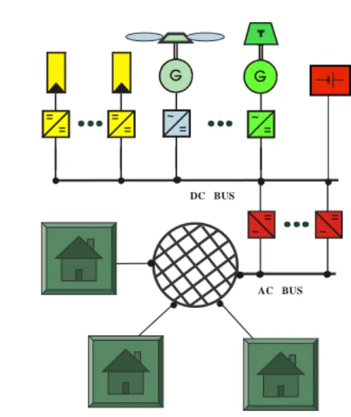
2.1Centralized DC-bus concept
AC BUS DC BUS = = ~ = = ~ = ~ = = ~ =
Figure 1: Structure of a modular centralized DC bus system
The characteristic of this system is that all generators are coupled on a DC bus. It is also a centralized hybrid system as the power delivered by all the energy sources is conditioned and controlled by a central unit and fed to the user loads via a single point of the distribution grid. The main advantage of the central hybrid systems is that they are more robust as they can be controlled more easily than the distributed systems. The communication between components is easy with short distances between the components. Usually, at each moment, only one grid-forming unit is connected to the user grid, while other units can act as current sources.
Compared to other commercial centralized DC bus hybrid products, the TTA TApS-Centralita offers a modular configuration that allows expandability of the system. The Centralita is a universal rack system for autonomous power supply. It consists of several modules (table 1), which may be combined according to the mini-grid requirements. Thus there are many possibilities to adapt the configuration of the centralita to the needs of the installation. The modularity also increases the efficiency of the system, as only the inverters really needed by the loads are operative. Figure 2 presents one of the many systems installed by TTA. The system provides electricity to 12 users in the village of Escuaín (Huesca, Spain). 5 PV charger modules condition the power from the 10.2 kWp PV field. A total of 7.5 kW AC power is provided to the users by 6 inverter modules. The Battery storage capacity is 180 kWh/48V. All the modules are plugged into two TApS C-8648 Units connected in parallel.
Modules Description
Energy management system (EMS)
One per system
PV battery charger 2kW per module, with
MPP tracker, max. 6 modules
Inverter controller One per system, includes
20W inverter for standby loads
Inverter power stages 1.25kW per module, max.
6 modules
External DC-supplies up to 10kW each
12V DC supply for telecommunication etc.
Table 1: Modules of the Centralita
Figure 2: Centralized DC-bus system: electrification of the village of Escuaín (Huesca, Spain)
2.2Distributed AC-bus concept
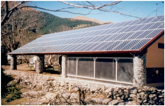
Distributed systems are feeding the user grid from multiple points and all the generators are coupled directly via the distribution grid. Distributing the generators along the grid is the technology normally used only with the bigger power systems while it makes the grid control more sophisticated (local robust generator controls or fast communication between each generators and a supervisory control are necessary). Especially, the parallel operation of multiple grid forming generators requires new devices for synchronisation, load sharing, ... Advantages of the distributed systems are a theoretically unlimited expandability, the reduction of distribution line costs, decentralised location for the RE generators allowing e. g. PV integration in building roofs.
= ~ = ~ = ~ = ~ = ~ = ~ ~ =
The Sunny family of products from SMA Regelsysteme GmbH comprises several modular components:
• Sunny Island: a single phase 3,3 kW bi-directional
battery inverter able to work as an AC grid-forming unit. This component includes all the mini-grid supervisory controls. 3 Sunny Island can be connected in parallel to build a 3-phase grid if needed.
• Sunny Boy: a family of single phase current source
PV inverters ranging from 450W to 2200W
• Sunny Boy Control for data acquisition
This new AC coupled technology for hybrid systems has been extensively described by B. Burger [2]. Since April 2001, 3 demonstration systems are running successfully on the Greek island of Kythnos [1]. The high modularity of the technology allows to easily building a single phase or a three-phase system. Several battery inverters can operate in parallel on one phase in order to increase the peak power of the power plant. The present research lead by ISET on the AC bus technology focuses on power sharing between distributed generators without communication [3].
Figure 4: Example of distributed AC bus system: village on Kytnos Island (PV MORE and MODE projects [1])
2.3Analysis of power plant performance
When using the distributed AC bus technology, it might be desirable in some cases to locate all the power generators at the same location. In the power range up to 10 kW, both the Sunny Island from SMA and the Centralita from TTA can be used to control a central power plant. The question, which arises especially with PV energy input, is then: Which of the AC or DC bus systems is more efficient?
Comparison of the performances of the two system concepts has been presented by Gabler et al. [ 6 ] for a typical European remote farm load profile. The results show similar results for both concepts. It shows also clearly the influence of the performances of the different inverters involved in the power conditioning process.
In order to study more specifically the influence of the load profile and of the solar fraction, a PV sizing simulation program in the Matlab/simulink environment has been used. The simulated hybrid power plant is a photovoltaic/battery/diesel system. In order to avoid influences of too many parameters, the following assumptions are made: (a) the simulation period is one clear day; (b) the battery state of charge never reaches overcharge levels during that period and there are no losses due to PV field disconnection, (c) the back-up generators runs at constant power in the evening and provides enough energy to complement the daily production of the battery. The more recent efficiency curves for bi-directional battery inverters, PV inverters, PV MPPT have been used. Similar devices have the same efficiencies in both AC and DC bus concepts. Four different 20 kWh load profiles have been used; two are real and two are theoretical:
• Night profile: This theoretical profile represents an
extreme situation of having load only by night.
• TransIndo [8]: This measured load profile, with an
important evening peak is typical for rural villages in developing countries. Most of the energy is consumed by lighting and entertainment appliances
• STBH [7]: it represents the measured load profile for
a typical alpine lodge. With more productive appliances used during working hours, more energy is used during the day when the sun shines. This profile would also apply for a village with income generating activities.
• Day profile. This theoretical profile represents a
perfect correlation between the load and the power available from the PV generators
0 500 1000 1500 2000 2500 3000 3500 0 2 4 6 8 10 12 14 16 18 20 22 24 Time of the day (hours)
Loa d c o ns um pti o n ( W ) Night Transindo STBH Day
Figure 5: Four 20 kWh Daily Load profiles
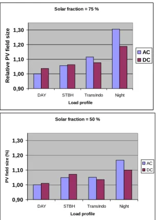
Solar fraction = 75 % 0,90 1,00 1,10 1,20 1,30
DAY STBH TransIndo Night
Load profile Re la ti ve P V f iel d si z e AC DC Solar fraction = 50 % 0,90 1,00 1,10 1,20 1,30
DAY STBH TransIndo Night
Load profile P V f iel d siz e ( % ) AC DC
Figure 6a+b: comparison of performance of the AC and
DC bus concepts for 4 load profiles and 2 solar fractions Results from the simulation are presented on figures 6a+b for two different solar fractions (50% and 75%). The final performance indicator is the size of PV generator, relative to the most favourable case. It can be seen that for high solar fraction (PV systems with little use of the fuel
genset), the DC system is generally preferable, unless most of the energy is consumed during the daytime. For hybrid systems, with a decreasing solar fraction, the AC system becomes more and more efficient compared to the DC system. The AC system should thus be recommended when the genset energy share is high and when a lot of energy is used during the day, while the DC system should be preferred for high evening consumption and high solar fraction.
3. ENERGY MANAGEMENT SYSTEM (EMS)
The objective of the project is to build a flexible Energy Management System, dedicated for user, multi-generator mini-grids, with remote control functions. The structure of the EMS is described on Figure 7.
3.1 Communication between components
The prototype of the EMS is based on the SMA inverter. SMA OPC server manages the communication between the industrial PC that runs the EMS and the inverter. This allows accessing all system data that is provided by the inverter with the LabView environment.
By using an additional EIB OPC server, the EMS provides the pricing signal to the users. In the opposite direction, this server is used for further data acquisition and counting or billing purposes by allowing reading out the consumers’ counters via the EIB.
Additionally a GSM modem allows connecting to the EMS from remote places. This feature is used for system set-up, supervision and diagnostics and to provide climatic forecast data to the EMS.
SMA Driver OPC SMA Driver OPC EIB Driver OPC LabVIEW Driver OPC RS485 RS232 RS232 Log Files GSM Modem Industrial PC G Consumer TTA EIB RS232 Pricing Management Components Data Base Setup Data Acquisition Consumer Remote Access LabVIEW Resource DB Load DB SMA Driver OPC SMA Driver OPC EIB Driver OPC LabVIEW Driver OPC RS485 RS232 RS232 Log Files GSM Modem Industrial PC G ConsumerConsumer TTA EIB TTA EIB RS232 Pricing Management Components Data Base Setup Data
Acquisition ConsumerConsumer
Remote Access LabVIEW Resource DB Load DB Resource DB Resource DB Load DB Load DB
Figure 7: Energy Management System Concept 3.2 Strategies
The management strategy consist of three main parts: a) For storing all necessary system data, a “components and system set-up database” was created. All information concerning the system, its structure and its components is stored here in an ASCII text. This database can be updated directly at the controller, radio modem or local area networks. An assistant allows the operator to set-up new components based on a model database, change the components properties and lookup the actual status.
b) In order to realise a prediction of energy supply and load demand “Resource and Load” modules were implemented. These modules are responsible for the acquisition, storing and management of the load and weather data. Both modules are using a database (DB) to organise the data and to calculate resource and load prediction values for a certain period. The load module uses a daytype configuration file. A day categorisation can be made here. Load profiles will differ on weekdays and the weekend and will probably differ on Saturdays and Sundays.
The Weather module uses one or more data sources. The weather station (at minimum a calibrated solar cell) is available in each system. Additionally the weather module uses data from the European Irradiation Atlas, or other solar radiation databases, which could be updated via a network connection. Furthermore the German weather service (DWD) offers daily irradiation forecasts for many major locations in Europe as a FTP download from the Internet. With an Internet connected EMS System this provides the most accurate predictions. From all these sources the weather module is able to calculate a prediction for a desired time period from 10 minutes to several days.
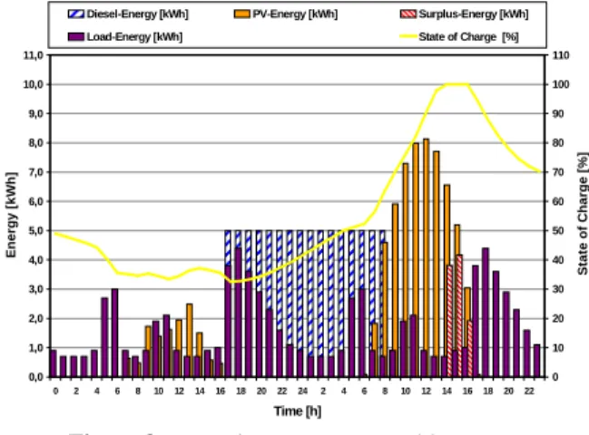
Both predictions are used to schedule the genset start-time at the beginning of a day to prevent the necessity to dump excessive PV energy [9]. 0,0 1,0 2,0 3,0 4,0 5,0 6,0 7,0 8,0 9,0 10,0 11,0 0 2 4 6 8 10 12 14 16 18 20 22 24 2 4 6 8 10 12 14 1618 2022 Time [h] En e rg y [ k W h ] 0 10 20 30 40 50 60 70 80 90 100 110 S tate o f C h ar g e [% ]
Diesel-Energy [kWh] PV-Energy [kWh] Surplus-Energy [kWh]
Load-Energy [kWh] State of Charge [%]
Figure 8: Excessive PV energy problem
c) The management and pricing modules calculate the actual energy price depending on the system data and the actual system state. The management module controls the auxiliary generators by taking into account the resource and load prediction, the energy price, the system state and the system set-up.
The pricing module calculates an energy price based on real economical aspects. It distinguishes fixed from variable costs. Fixed costs are all costs that are not related to operation like installation, capital and some maintenance costs. Variable costs are operational costs for fuel, wareout and maintenance that only occur on operation of the genset or battery. The fixed costs are used to calculate the costs per day and with the load forecast the costs per kWh as a base price level. When the genset or the battery has to be operated for additional supply, the variable price per kWh depending on the generation is
added to the base price. This results in the total energy price that is charged from the consumer.
This pricing system has two major advantages: The ability of billing the consumed energy and a demand side management by giving the consumer the motivation to consume energy at low prices when no auxiliary generation is required.
4 USER CONTROL
The user control mechanisms introduced here, is a further development of the TTA “Energy Dispenser” realised for stand alone village grids [5]. The control mechanism is implemented in a laboratory prototype of a novel energy counter.
4.1 Lessons learned with stand alone mini grids
Experience shows that operation of mini grids is frequently disturbed by power plant overloads causing black outs to the community. In the same way the economical base of mini grids can be disturbed if the collective of users don’t meet the determined contractual agreements, if the determined energy demand was falsely estimated or if the customers don’t pay the energy bill. The mentioned problems could be prevented by
• Limiting available power for the users. This individual
power limit will be defined in a “Supplying Contract” with the system operator. The energy counter will control the limitation.
• Limiting energy use. The expected energy
consumption will be defined in the same “Supplying Contract”.
• Encouraging the user to choose pre-payment methods.
The functional operation can be best illustrated by the analogy of telecommunication contracts in the mobile market, where such pre-payment concepts are successfully implemented. This concept contains a time limited unit account (i.e. Xtra Card). This makes it possible to size the system.
Further more to control the energy flow in a suitable way the individual user will be motivated with the mentioned variable price to change their habit.
4.2 Tariffs
During operation the energy base price is modified by the price factor determined by the EMS. In order to control the energy demand as well as to cover operation related costs. For example, deep cycling of the batteries or operation of fuel generator influences the end user price. Modularity of the system design allows easy expansion of power and energy generation. Thus the user may modify the tariff selected.
4.3 Energy counter
The user energy counter is under development by TTA. The energy consumption is weighted with a price factor, which is determined by the EMS. This helps the user to adapt their consumption behaviour to the generation
profile of the system. It limits the power of the users loads, provides information to the user and cuts the energy supply when the users credit is exhausted.
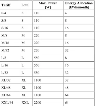
Tariff Level Max. Power
[W] Energy Allocation [kWh/month] S/4 S 110 4 S/8 S 110 8 S/16 S 110 16 M/8 M 220 8 M/16 M 220 16 M/32 M 220 32 L/8 L 550 8 L/16 L 550 16 L/32 L 550 32 XL/32 XL 1100 32 XL/48 XL 1100 48 XL/64 XL 1100 64 XXL/64 XXL 2200 64
Table 2: Example of a tariff system where the price per
tariff is depending on the individual system
4.4User information
The user is provided with the complete information necessary for his proper load management. This information includes:
• consumptions made
• actual energy price information
• remaining validity of the prepayment
4.5Load management tools
User load management tools allow for an automated management of the user’s appliances. So it is possible to automatically switch on certain loads only when the energy price is sufficiently low. These devices also allow using passive energy storage in low energy price situations. As an example, the pump of a water pumping system can be started in low energy price situations, in order to fill up the tank.
5 CONCLUSIONS
Two modular hybrid power system architectures have been identified:
• The centralized DC-bus system TApS-Centralita
from the company Trama Tecnoambiental S.L.
• The distributed AC-bus system Sunny family from
the company SMA Regelsysteme GmbH
Energetic comparison of the two concepts for several load profiles and solar fractions shows that the DC bus concept achieves better results with high solar fractions and evening loads (Typically, a PV/battery system for lighting and entertainment loads). However, when the solar
fraction decreases and more productive loads are used, then the AC bus system becomes more efficient.
A new Energy Management System (EMS), specially adapted to multi-user, multi-generator and remote management is under development. Its functionality include variable energy pricing, load and RES prediction, intelligent load control, multi-bus communication... The EMS is able to influence the user behaviour by communicating with an Energy Dispenser located in each household. The Energy Dispenser is based on the existing product from TTA and will include new functions for variable energy pricing, user information and load control.
6 ACKNOWLEDGEMENT
This research is partially funded by the European Commission within the framework of the Non Nuclear Energy Program JOULE 3, under the project Mini-Grid Kit NNE5-1999-00487
7 REFERENCES
[1] Ph Strauss, R.-P. Wurtz et al.: Stand-Alone Ac Pv Systems And Micro Grids With New Standard Power Components – First Results Of Two European Joule Projects “Pv-Mode” And “More”, 16th Epvsec, 1-5 May 2000, Glasgow, Uk.
[2] B. Burger, G. Cramer, W. Kleinkauf, P. Zacharias: Hybrid Systems – Easy in Configuration and
Applica-tion, 16th EPVSEC, 1 - 5 May 2000, Glasgow, UK
[3] A. Engler, C. Hardt, P. Strauss & M. Vandenbergh Parallel Operation of Generators for Stand-Alone Single-Phase Hybrid Systems – First Implementation
of a New Control Technology, 17th EPVSEC, 22-26
October 2001, Munich, Germany
[4] X. Vallvé et al., First Experiences from the Electrification of Rural Villages in Spain with
Multi-User Solar Hybrid Grids (MSG), 17th EPVSEC, 22-26
October 2001, Munich, Germany
[5] X. Vallvé, J. Mertens, E. Figuerol, Innovative load management for multi-user PV stand-alone systems,
2nd World PV Conference, 6-10 July 1998, Vienna,
Austria
[6] Gabler H., Wiemken E.: „Modelling of stand-alone PV-hybrid systems and comparison of system
concepts“, 2nd World PV Conference, 6-10 July 1998,
Vienna, Austria
[7] M. Landau, T. Krieger, C. Schmitz, P. Zacharias: Successful implementation of a Hybrid System based on Modular Systems Technology in the Alpine Lodge
"Starkenburger Hütte", 2nd World Conf. on PV Solar
Energy Conversion, Vienna 1998.
[8] J.-C. Marcel, G. Moine, P. Schweizer-Ries, Rural PV diesel hybrid systems in Indonesia, Socio Technical analysis two years after implementation, PVHPS 2000, 7-9 September 2000, Aix en Provence, France [9] Benjamin Wichert, Control of Photovoltaic-Diesel
![Figure 4: Example of distributed AC bus system: village on Kytnos Island (PV MORE and MODE projects [1])](https://thumb-eu.123doks.com/thumbv2/123doknet/12713681.356274/4.892.104.792.312.804/figure-example-distributed-village-kytnos-island-mode-projects.webp)